

1970 GTO Version 3.0
 05-06-2021 | 10:20 AM
#242
Thread Starter

Joined: Mar 2003
Posts: 10,222
Likes: 1,511
From: The City of Fountains
I have been making slow progress with the wiring. Mostly looking at things and planning things. The goal is to make the wiring as tidy as possible, while still being accessible for service. I also don't want any wires to be randomly hanging off the engine, so everything that goes to the engine must come through the EFI harness.
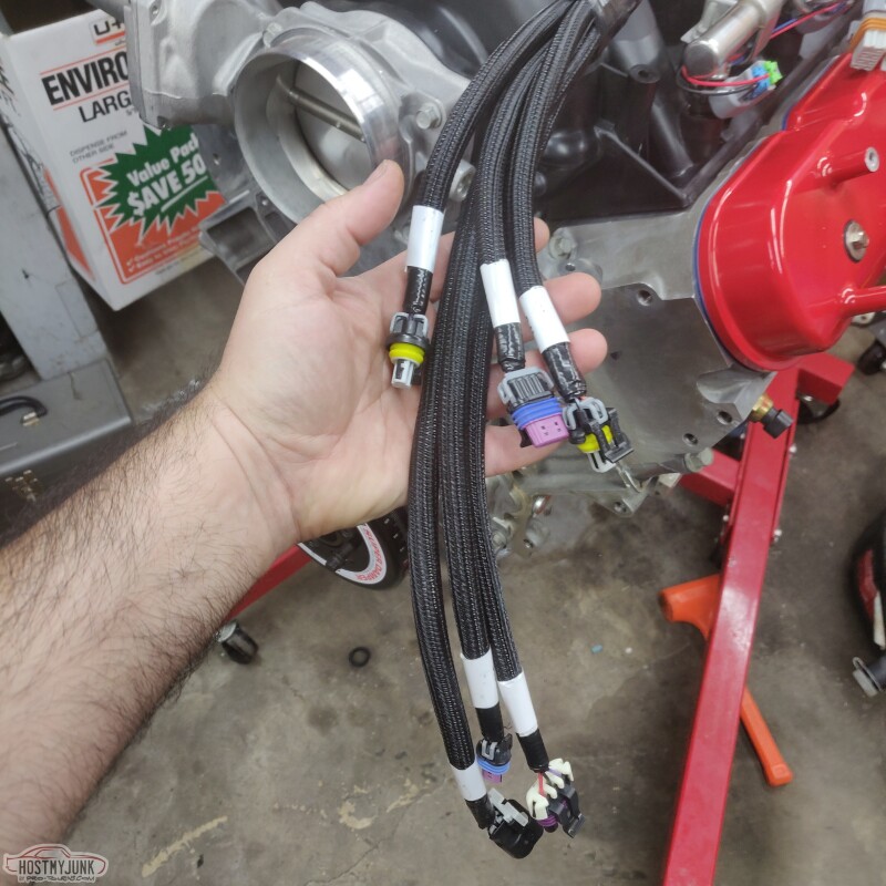
This is the hexapus (if that is not a word, it should be) on the driver's side of the Terminator X harness. It extends forward and contains the CTS, cam sensor, TPS, IAC, fuel pressure, and MAT sensor plugs. CTS, MAT, and cam sensors are workable. The TPS and IAC need to be eliminated, and the fuel pressure needs to be stripped out and moved all the way to the rear of the engine. I also need to add the connector for the alternator for the L and S terminals, and route them all the way through into the passenger compartment.
Recently, I was looking through the Delphi (Aptive) catalog and I spotted a few little items that I had never really paid much attention to.
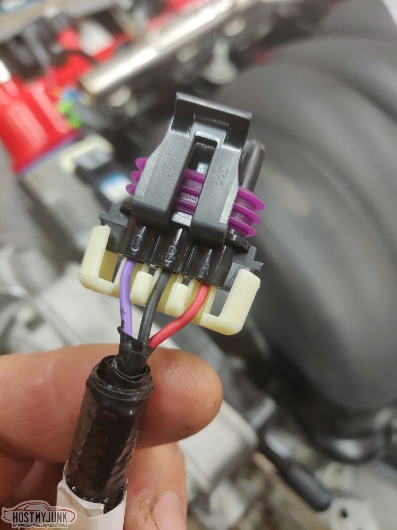
This is a typical Metripack 150 connector. This particular one is for the cam sensor. The white clip is called a TPA (terminal position assurance).
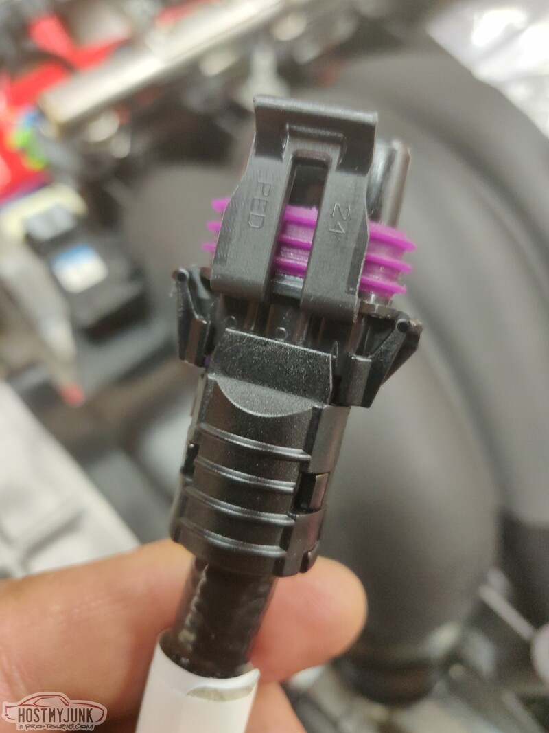
The part pictured below is also a TPA, but it is called a conduit TPA. It serves the same function as a regular TPA, but it has an added enclosure to protect the exposed wires after they exit the connector. I am going to use 4:1 heat shrink tubing to completely seal off some of the more sensitive connectors.
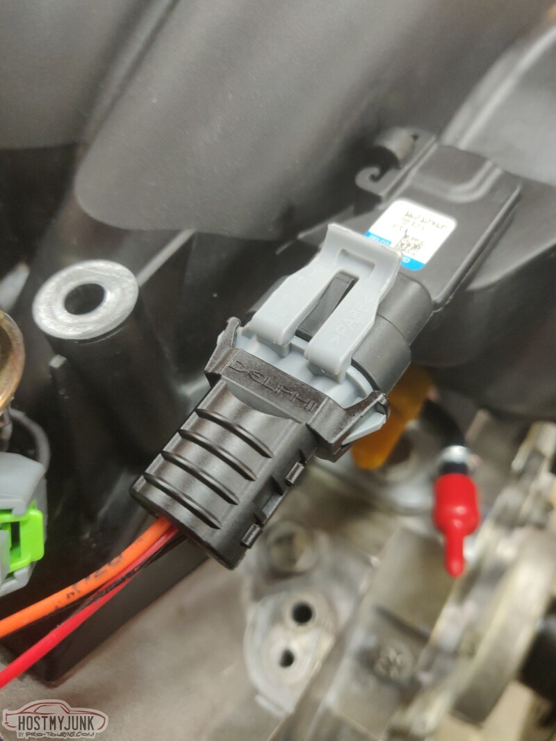
This is the MAP sensor, also with the conduit TPA.
There is a lot happening on the passenger side in terms of wiring. There are the injectors and the coils, and also the shielded cable for the DBW throttle body and three wires for the MAP sensor. I am waiting on some supplies to arrive before I get things fully sorted here.
I also mocked up the Holley mid-mount main casting. This is the bracket that holds all of the accessories in place. I wanted to see what kind of room I have for routing parts of the harness.
There is a nice path and clearance for the cam sensor.
I also mocked up the shaker scoop assembly. Of course with it in place, the wiring is barely visible, but I know it will be good, even if it is not clearly visible.
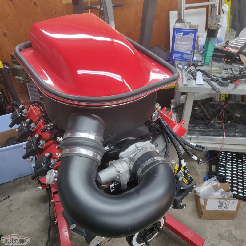
The last area of concern is the clearance between the intake tube and the AC compressor. I think it will be a tight fit, based on the pictures of a fully assembled mid-mount. If there is interference, I will deal with that later.
That's all for now.
Andrew
This is the hexapus (if that is not a word, it should be) on the driver's side of the Terminator X harness. It extends forward and contains the CTS, cam sensor, TPS, IAC, fuel pressure, and MAT sensor plugs. CTS, MAT, and cam sensors are workable. The TPS and IAC need to be eliminated, and the fuel pressure needs to be stripped out and moved all the way to the rear of the engine. I also need to add the connector for the alternator for the L and S terminals, and route them all the way through into the passenger compartment.
Recently, I was looking through the Delphi (Aptive) catalog and I spotted a few little items that I had never really paid much attention to.
This is a typical Metripack 150 connector. This particular one is for the cam sensor. The white clip is called a TPA (terminal position assurance).
The part pictured below is also a TPA, but it is called a conduit TPA. It serves the same function as a regular TPA, but it has an added enclosure to protect the exposed wires after they exit the connector. I am going to use 4:1 heat shrink tubing to completely seal off some of the more sensitive connectors.
This is the MAP sensor, also with the conduit TPA.
There is a lot happening on the passenger side in terms of wiring. There are the injectors and the coils, and also the shielded cable for the DBW throttle body and three wires for the MAP sensor. I am waiting on some supplies to arrive before I get things fully sorted here.
I also mocked up the Holley mid-mount main casting. This is the bracket that holds all of the accessories in place. I wanted to see what kind of room I have for routing parts of the harness.
There is a nice path and clearance for the cam sensor.
I also mocked up the shaker scoop assembly. Of course with it in place, the wiring is barely visible, but I know it will be good, even if it is not clearly visible.
The last area of concern is the clearance between the intake tube and the AC compressor. I think it will be a tight fit, based on the pictures of a fully assembled mid-mount. If there is interference, I will deal with that later.
That's all for now.
Andrew
The following users liked this post:
Project GatTagO (05-06-2021)
05-06-2021 | 10:47 AM
#244
Thread Starter
Joined: Mar 2003
Posts: 10,222
Likes: 1,511
From: The City of Fountains
05-06-2021 | 11:20 AM
#245
TECH Fanatic
Joined: Nov 2014
Posts: 1,176
Likes: 544
05-06-2021 | 11:41 AM
#246
Thread Starter
Joined: Mar 2003
Posts: 10,222
Likes: 1,511
From: The City of Fountains
Andrew
The following users liked this post:
LSswap (05-06-2021)
05-06-2021 | 12:03 PM
#247

TECH Senior Member
Joined: Jun 2016
Posts: 21,513
Likes: 3,277
From: Central Cal.
I totally get that, but this way you'll know where to mod the piece and/or design before you get much further. Unless, of course, I'm not seeing this correctly ....
05-06-2021 | 01:44 PM
#248
Great catching up with you yesterday Andrew.
I'm wondering (and you didn't ask), but would a carb style intake + flat mounted TB have any chance of lining up with your scoop? Just curious.
I'm wondering (and you didn't ask), but would a carb style intake + flat mounted TB have any chance of lining up with your scoop? Just curious.
The following users liked this post:
Project GatTagO (05-07-2021)
The following 2 users liked this post by Jimbo1367:
G Atsma (05-06-2021), Project GatTagO (05-07-2021)
05-07-2021 | 11:16 AM
#250
Thread Starter
Joined: Mar 2003
Posts: 10,222
Likes: 1,511
From: The City of Fountains
Andrew
The following users liked this post:
daytripper67mi (05-08-2021)
05-08-2021 | 10:17 PM
#251
Thread Starter
Joined: Mar 2003
Posts: 10,222
Likes: 1,511
From: The City of Fountains
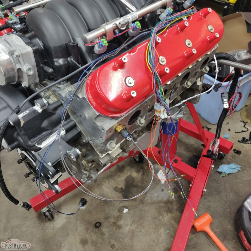
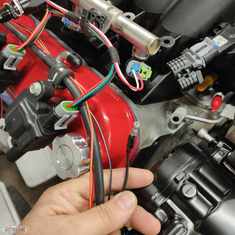
Before making any cuts to the harness, I needed to establish its best position relative to the engine. Since the hole for the harness is offset to the driver's side slightly, it made sense that the harness needs to come from that direction.
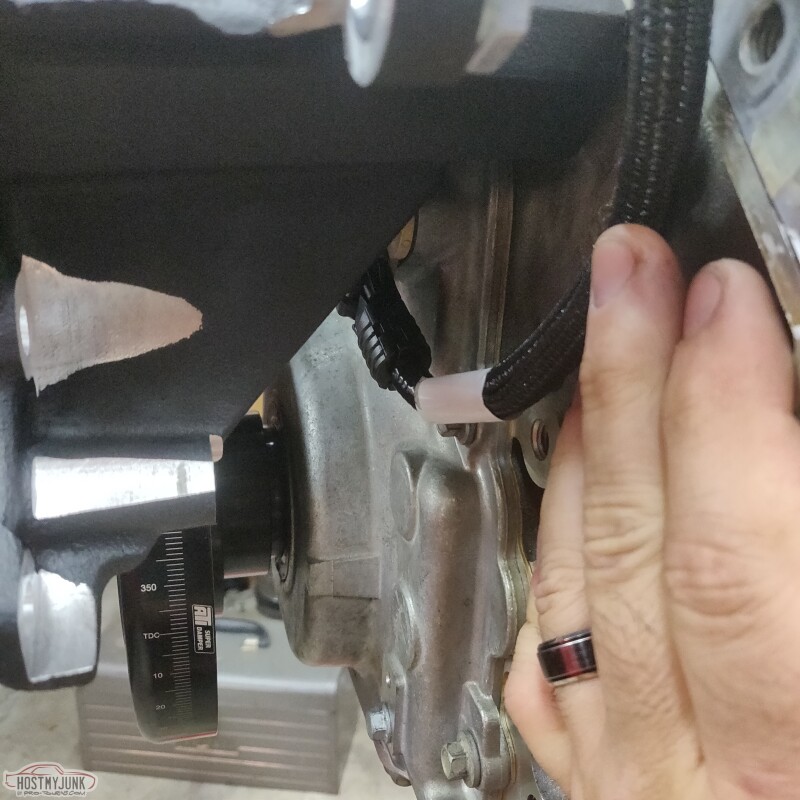
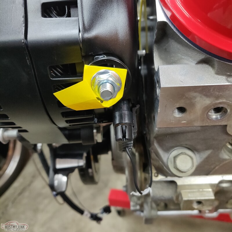
The determining factor was also the crank sensor lead, which I really don't want to modify, because it is a shielded cable. I also used a bolt/stud that I had left over from doing the Cougar. I used a P clamp on it to keep the knock sensor out of the way of the headers.
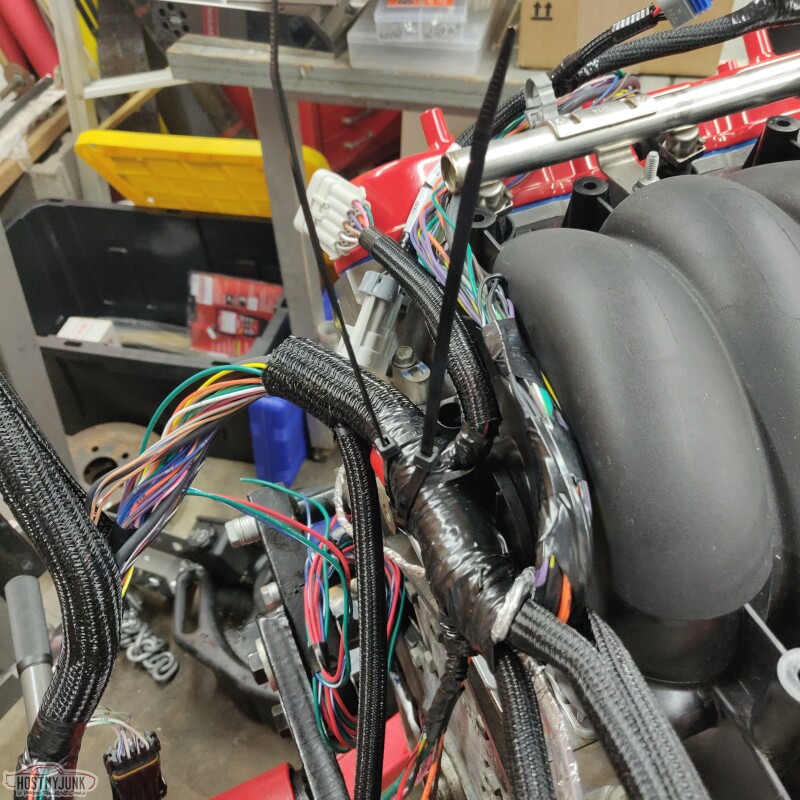
I unwrapped the driver's side hexapus. The TPS and the IAC are not needed, but I may repurpose two of them for the alternator L and S terminals.
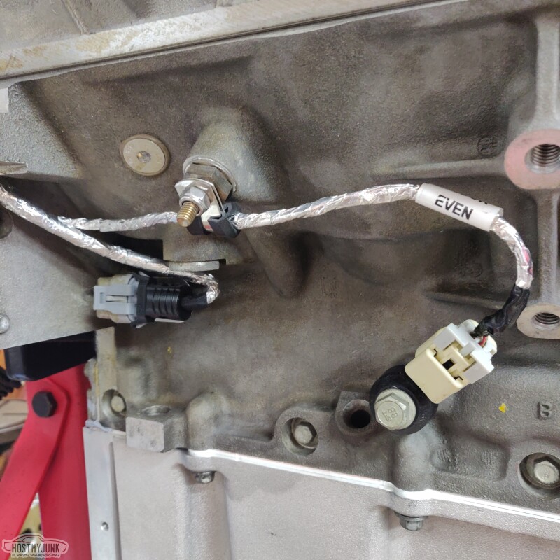
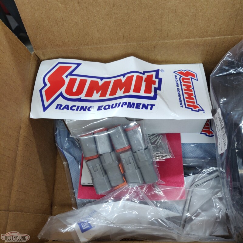
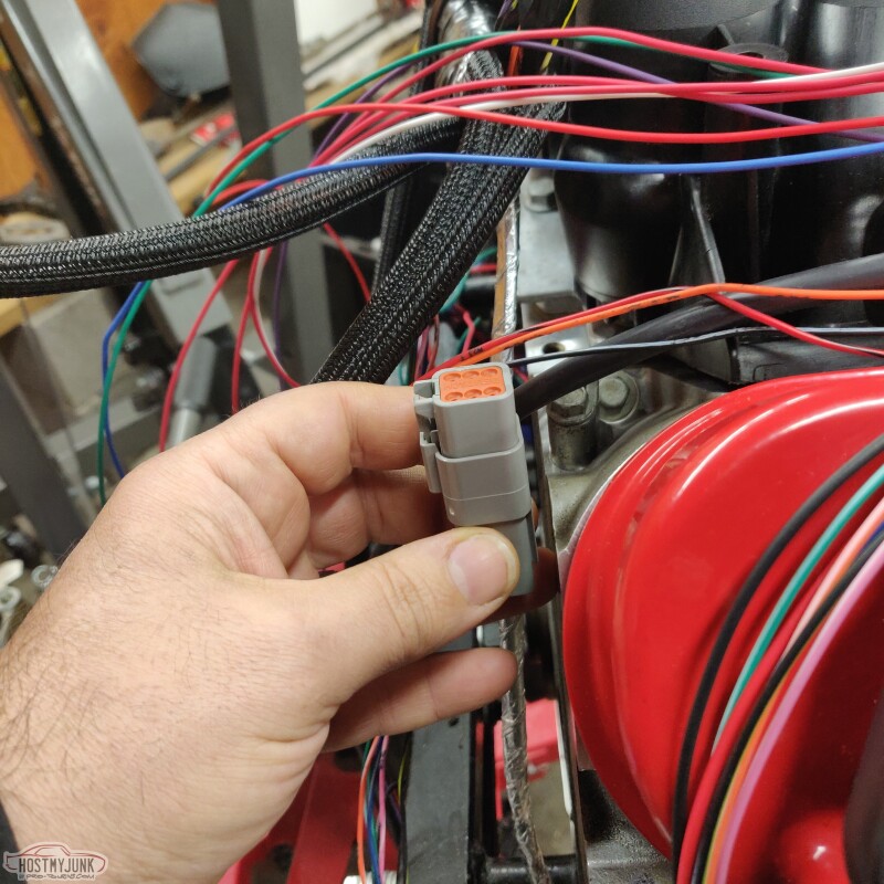
Summit Racing had some Deutsche connectors and terminals in stock. These are going to replace the coil harness connectors and the injector connector. There will be an ODD and EVEN injector connector and a ODD and EVEN coil connector.
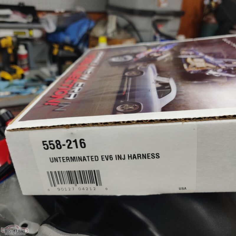
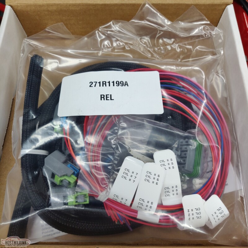
I also decided that I was going to build my own injector harness. The Holley one was OK, but I can make it better.
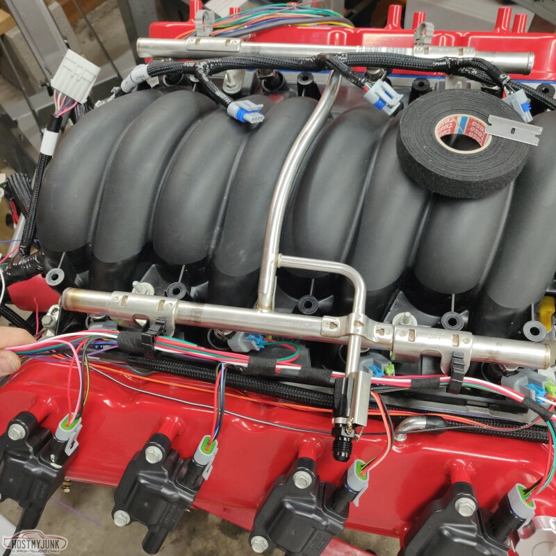
I played around with different routing paths.
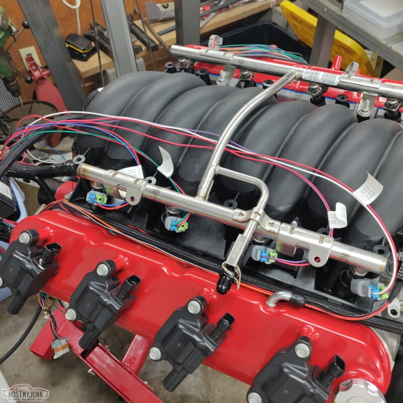
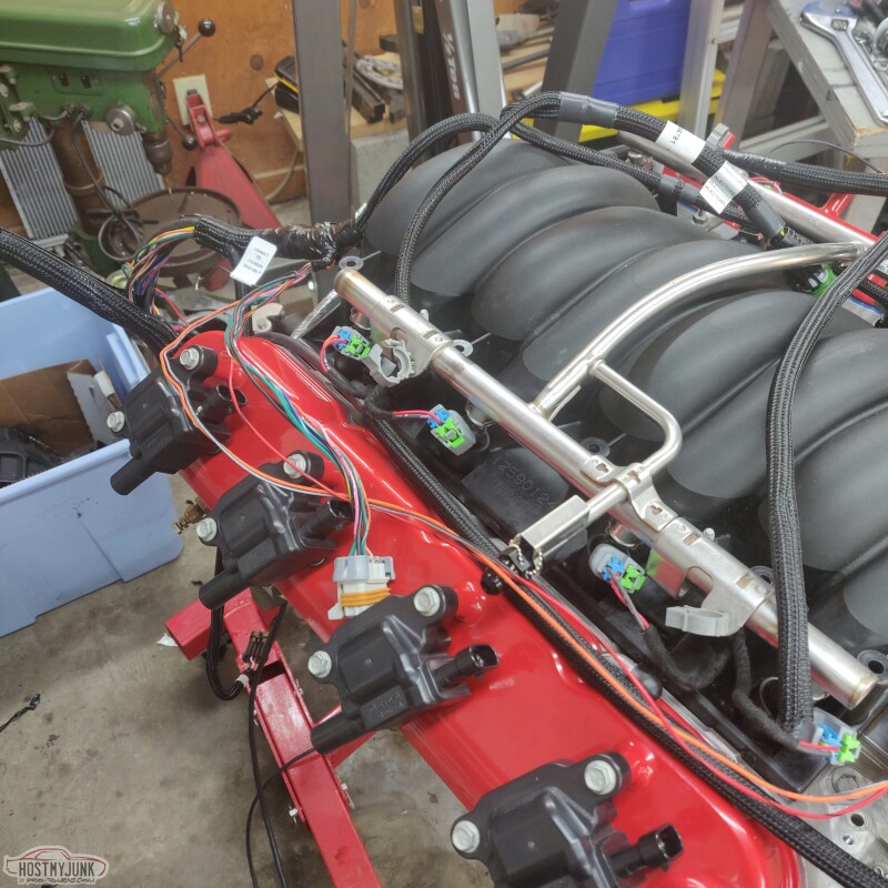
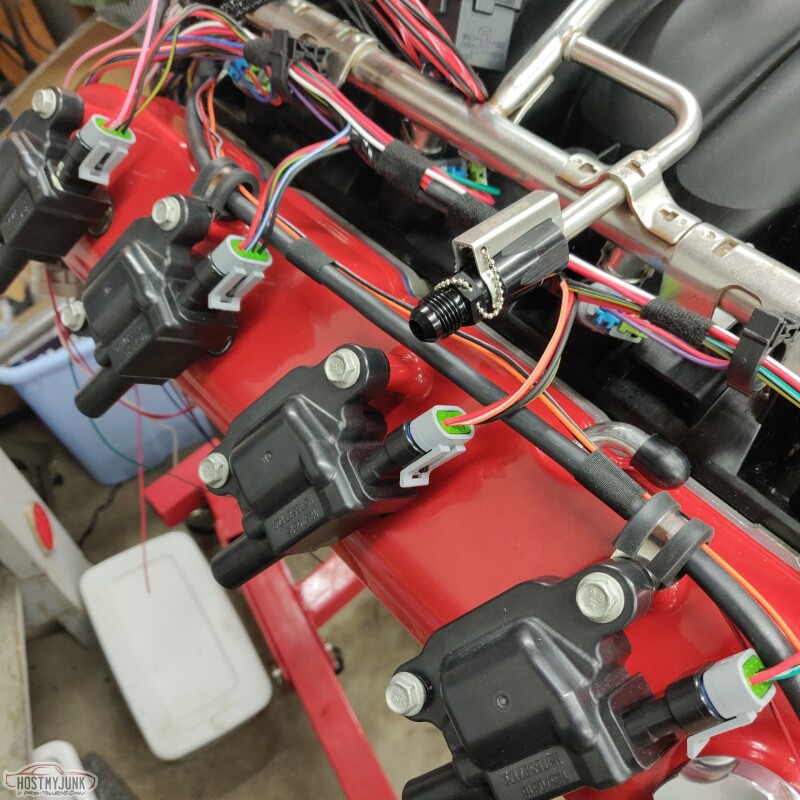
Ultimately I decided that the injectors should run along with the coil sub harness.
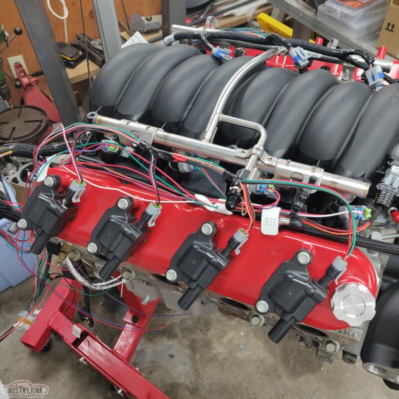
It's all a bit of a mess still, but this is the basic layout. The fuel rails have little tabs on them with holes, which are designed to hold harness clips. I bought an assortment of harness clips, which you can see on the rails.
Andrew
The determining factor was also the crank sensor lead, which I really don't want to modify, because it is a shielded cable. I also used a bolt/stud that I had left over from doing the Cougar. I used a P clamp on it to keep the knock sensor out of the way of the headers.
I unwrapped the driver's side hexapus. The TPS and the IAC are not needed, but I may repurpose two of them for the alternator L and S terminals.
Summit Racing had some Deutsche connectors and terminals in stock. These are going to replace the coil harness connectors and the injector connector. There will be an ODD and EVEN injector connector and a ODD and EVEN coil connector.
I also decided that I was going to build my own injector harness. The Holley one was OK, but I can make it better.
I played around with different routing paths.
Ultimately I decided that the injectors should run along with the coil sub harness.
It's all a bit of a mess still, but this is the basic layout. The fuel rails have little tabs on them with holes, which are designed to hold harness clips. I bought an assortment of harness clips, which you can see on the rails.
Andrew
The following 2 users liked this post by Project GatTagO:
2ToeRacing (07-15-2023), G Atsma (05-08-2021)
The following users liked this post:
Project GatTagO (05-09-2021)
05-09-2021 | 08:00 AM
#253
Thread Starter
Joined: Mar 2003
Posts: 10,222
Likes: 1,511
From: The City of Fountains
05-09-2021 | 12:26 PM
#254

TECH Senior Member

Joined: Jul 2009
Posts: 7,927
Likes: 607
Could you please paste a link for the pass through booot?
I know I�ve been looking for something to shrink to a battery terminal bulkhead. I would imagine this could help others
thank you,
jim
Last edited by Jimbo1367; 05-09-2021 at 12:32 PM.
The following users liked this post:
Project GatTagO (05-09-2021)
05-09-2021 | 04:31 PM
#255
Thread Starter
Joined: Mar 2003
Posts: 10,222
Likes: 1,511
From: The City of Fountains
I am not sure if it will work for that, but they are on page 85 of the Waytek catalog:
https://catalog.waytekwire.com/Wayte...atalog-233/85/
Andrew
The following users liked this post:
Project GatTagO (05-12-2021)
05-12-2021 | 12:17 PM
#257
Thread Starter
Joined: Mar 2003
Posts: 10,222
Likes: 1,511
From: The City of Fountains
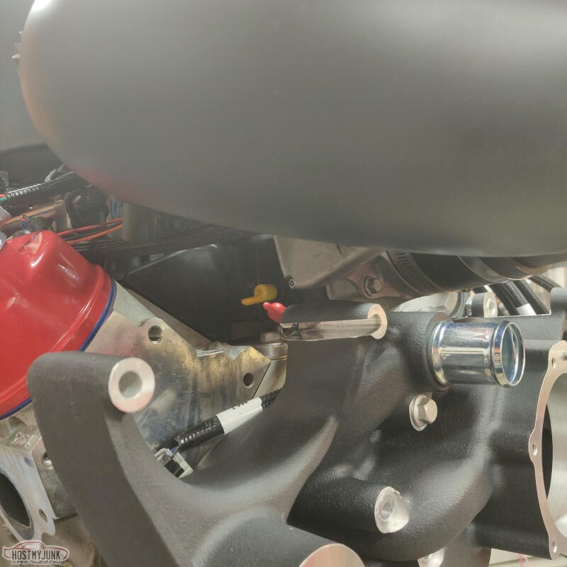
This is my current thinking to tuck away the coil and the injector connectors. There is enough room at the back of the heads to attach little brackets and hang the connectors there. This will tuck them out of sight, but also make them fairly accessible for service. I have more parts on the way from wirecare.com to make it all work.
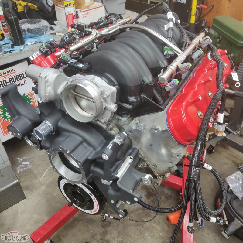
I mocked up the alternator, just to see how it fits and see how the wiring for it has to be routed. The alternator need two wires, and instead of adding wires to the harness, I will repurpose two of the unused IAC wires.
I also mocked up the AC compressor, which needs to have a wire added for it. I am hesitant to use one of the other IAC wires, because they are 20 gauge and that may not be enough for the compressor.
I also mocked up some P-clamps to hold the DBW and the MAP sensor wires. I am still debating if I like this or not. I also have some small nylon P-clamps which I might try in that location.
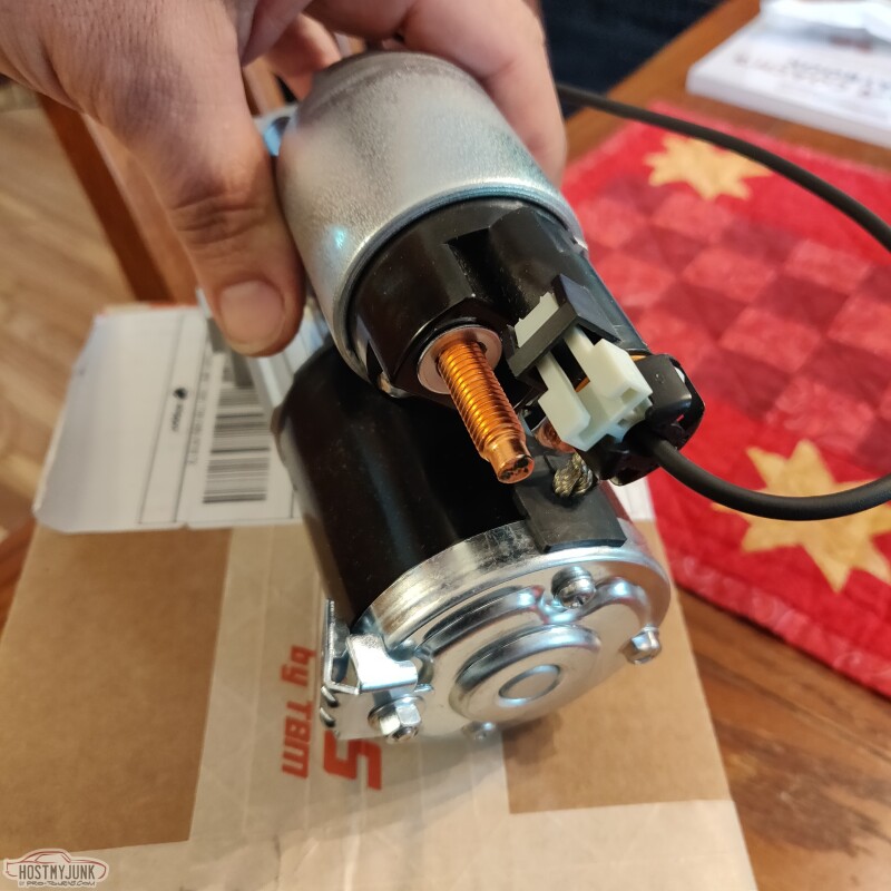
I also picked up a 5th Gen Camaro starter. I like it because it has mounting tabs for a heat shield and uses a plug for the solenoid, instead of a ring terminal. The starter wire will run along with the crank sensor wire.
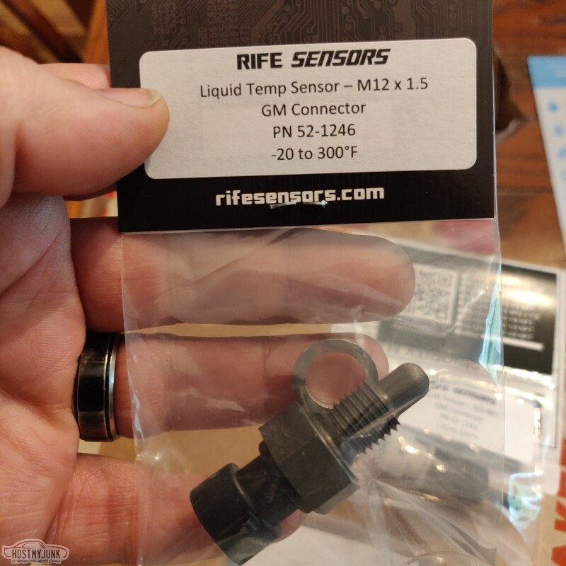
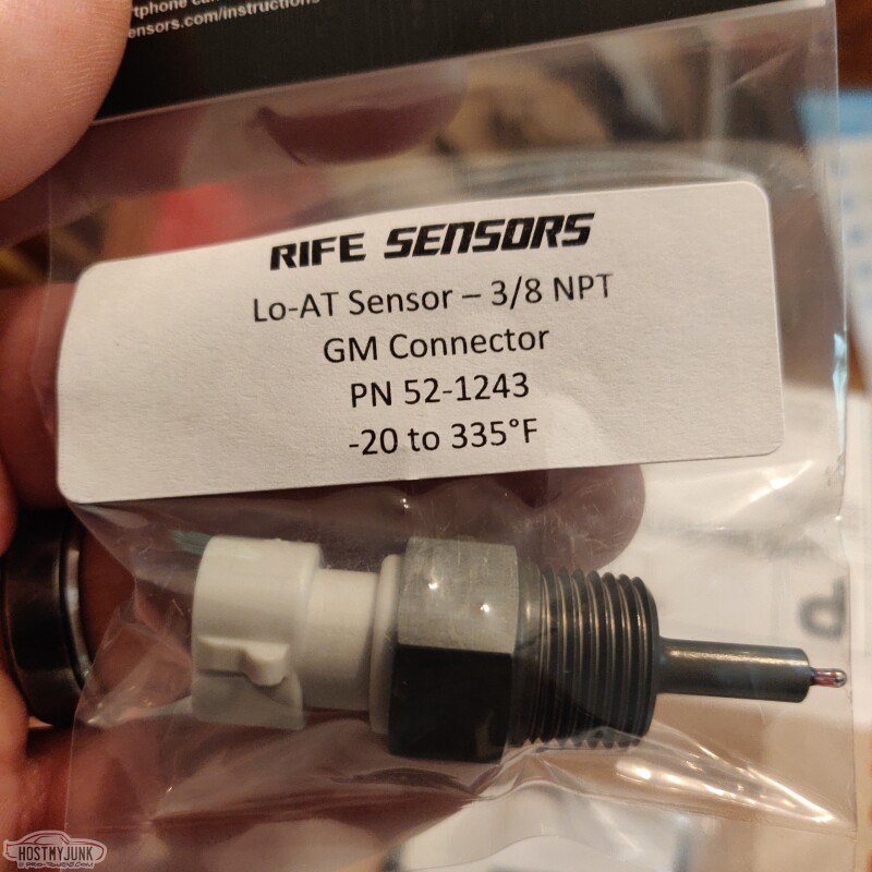
I also got a couple of Rife sensors for the coolant and air temps. These are supposed to be faster reacting than regular sensors.
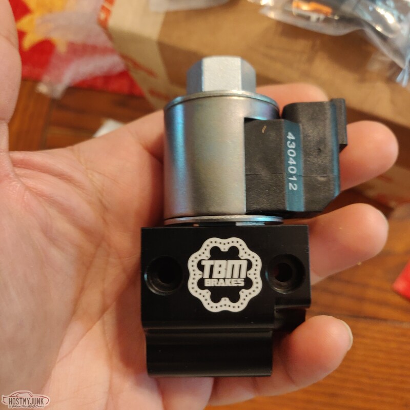
Rife is owned by The Brake Man brakes, and I saw they have a very cleverly designed line lock solenoid. It accepts both SAE double flare connections or AN-3, and also comes with a tidy Deutsche connector.
My buddy Tom is flying in from Alabama this weekend and our big project is to bolt on all of the Ridetech components. Wish us luck!
Andrew
I mocked up the alternator, just to see how it fits and see how the wiring for it has to be routed. The alternator need two wires, and instead of adding wires to the harness, I will repurpose two of the unused IAC wires.
I also mocked up the AC compressor, which needs to have a wire added for it. I am hesitant to use one of the other IAC wires, because they are 20 gauge and that may not be enough for the compressor.
I also mocked up some P-clamps to hold the DBW and the MAP sensor wires. I am still debating if I like this or not. I also have some small nylon P-clamps which I might try in that location.
I also picked up a 5th Gen Camaro starter. I like it because it has mounting tabs for a heat shield and uses a plug for the solenoid, instead of a ring terminal. The starter wire will run along with the crank sensor wire.
I also got a couple of Rife sensors for the coolant and air temps. These are supposed to be faster reacting than regular sensors.
Rife is owned by The Brake Man brakes, and I saw they have a very cleverly designed line lock solenoid. It accepts both SAE double flare connections or AN-3, and also comes with a tidy Deutsche connector.
My buddy Tom is flying in from Alabama this weekend and our big project is to bolt on all of the Ridetech components. Wish us luck!
Andrew
The following 2 users liked this post by Project GatTagO:
2ToeRacing (07-15-2023), G Atsma (05-12-2021)
05-12-2021 | 01:33 PM
#258

Staging Lane
Joined: Aug 2009
Posts: 71
Likes: 42
Andrew,
Excellent information as always !
I am anxiously awaiting to see what Ridetech components you have selected as I just started researching what to use on my 67 Chevelle project that I'm starting.
Good luck !!
Ken
Excellent information as always !
I am anxiously awaiting to see what Ridetech components you have selected as I just started researching what to use on my 67 Chevelle project that I'm starting.
Good luck !!
Ken
The following users liked this post:
Project GatTagO (05-12-2021)
05-12-2021 | 02:11 PM
#259
TECH Senior Member
Joined: Jul 2009
Posts: 7,927
Likes: 607
Andrew,
I like the small nylon p-clamps for the small injector wires. I used black ones, I drilled and tapped the intake manifold so they are tight and blend in. I did consider running them under the intake and up the grove cast in the heads I decided on the pclanmp eventually thoygh
When do you think you�ll have this beast back on the road? I�m interested to hear how you like the Summit cam vs. the previous cam. Pros & cons of each
Thanks,
jim
Last edited by Jimbo1367; 05-13-2021 at 02:45 AM.
The following users liked this post:
Project GatTagO (05-12-2021)
The following users liked this post:
Project GatTagO (05-12-2021)