

1970 GTO Version 3.0
 04-29-2021 | 06:59 AM
#221
Andrew,
During your lifter preload session, would you mind giving a detailed explanation of what and why you�re doing it w/ pics?
If I keep my LY6, I foresee myself having to do a cam swap( shortly after it�s road worthy). Plus I�m sure it will help out a lot of people.
I�m sure I missed it somewhere, but what lifters are you going to run?thanks,
jim
Great question asking if he can detail the lifter preload as I too would like to learn more on that process.
The following 2 users liked this post by will69camaro:
2ToeRacing (07-15-2023), Project GatTagO (04-29-2021)

The following users liked this post:
Project GatTagO (04-29-2021)
04-29-2021 | 09:46 AM
#223
Thread Starter

Joined: Mar 2003
Posts: 10,222
Likes: 1,511
From: The City of Fountains
The lifters are stock, whatever came in a 2008 L92. Presumably they are the same as LS7 lifters, which are basically the same lifters that are used in most Gen 4 engines.
Andrew
Andrew
The following 3 users liked this post by Project GatTagO:
The following 2 users liked this post by -TheBandit-:
Project GatTagO (04-29-2021), Rick Dorion (01-31-2023)
04-29-2021 | 10:50 AM
#225
Thread Starter
Joined: Mar 2003
Posts: 10,222
Likes: 1,511
From: The City of Fountains
If it helps, I wrote an explanation of pushroad length / preload check in post 641 of my build thread here.
That's a great write-up! I don't have an adjustable push rod checker, but I do have two lengths of pushrods. So the plan is to check preload with both and see which one gets me into a better range.
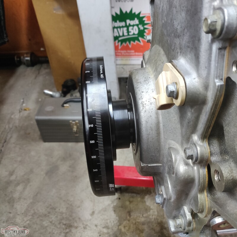
It might be time to dig out the balancer that came with my Holley mid-mount, because I am pretty sure it has degree markings all the way around. I don't plan on pinning the balancer, but it will be helpful to have markings when rotating the engine in the firing order, not that figuring out 90 degree increments is that hard...LOL
Andrew
The following users liked this post:
G Atsma (04-30-2021)
04-29-2021 | 11:21 AM
#226
Let me know if you want me to send you mine to borrow. In case you're not aware, pushrods aren't sized by the end-to-end length; they are sized by a gauge length with a fixed diameter (0.140") datum reference.
04-29-2021 | 11:26 AM
#227

TECH Senior Member
Joined: Jun 2016
Posts: 21,513
Likes: 3,277
From: Central Cal.
On this subject, I was a bit surprised that in Summit's reply to my pushrod question, they suggested 7.425 pushrods for an otherwise totally stock configuration, and (normally "stock" size) 7.400 for my setup w/ .040 HG and .020 milled heads. LS7 lifters must like more preload? Your statement above made me think you may end up with a longer-than-"normal" pushrod.
04-30-2021 | 09:54 AM
#228
LS1Tech Sponsor

Joined: Jan 2008
Posts: 2,041
Likes: 1,251
From: Ohio, Georgia, Nevada, Texas
G,
Keep in mind we referenced using the Ghost cam in an otherwise stock LM7. We recommended a 7.425" pushrod due to the .600"/.575" lift of the Ghost cam versus .457"/.466" of the stock LM7 cam. Then drop to a 7.400" when shaving .020" off the heads and going with .040" head gaskets.
Regarding lifter pre-load. With our LS7 spec lifters we recommend .050"-.075" pre-load. Our site might show .050"-.100" but we actually like that a little tighter at .050"-.075". We're having the site fixed to reflect this info.
With one of our .550" lift truck cams, you'd probably be at that 7.400" length with un-milled heads and stock head gaskets. Then with .020" off the heads and .040" head gaskets you'd probably be looking at a 7.375" pushrod.
As always, there are variables. That's why we recommend getting a pushrod length checker before purchasing pushrods

The following 2 users liked this post by Summitracing:
2ToeRacing (07-15-2023), G Atsma (04-30-2021)
04-30-2021 | 10:17 AM
#229
TECH Senior Member
Joined: Jun 2016
Posts: 21,513
Likes: 3,277
From: Central Cal.
G,
Keep in mind we referenced using the Ghost cam in an otherwise stock LM7. We recommended a 7.425" pushrod due to the .600"/.575" lift of the Ghost cam versus .457"/.466" of the stock LM7 cam. Then drop to a 7.400" when shaving .020" off the heads and going with .040" head gaskets.
Regarding lifter pre-load. With our LS7 spec lifters we recommend .050"-.075" pre-load. Our site might show .050"-.100" but we actually like that a little tighter at .050"-.075". We're having the site fixed to reflect this info.
With one of our .550" lift truck cams, you'd probably be at that 7.400" length with un-milled heads and stock head gaskets. Then with .020" off the heads and .040" head gaskets you'd probably be looking at a 7.375" pushrod.
As always, there are variables. That's why we recommend getting a pushrod length checker before purchasing pushrods
Keep in mind we referenced using the Ghost cam in an otherwise stock LM7. We recommended a 7.425" pushrod due to the .600"/.575" lift of the Ghost cam versus .457"/.466" of the stock LM7 cam. Then drop to a 7.400" when shaving .020" off the heads and going with .040" head gaskets.
Regarding lifter pre-load. With our LS7 spec lifters we recommend .050"-.075" pre-load. Our site might show .050"-.100" but we actually like that a little tighter at .050"-.075". We're having the site fixed to reflect this info.
With one of our .550" lift truck cams, you'd probably be at that 7.400" length with un-milled heads and stock head gaskets. Then with .020" off the heads and .040" head gaskets you'd probably be looking at a 7.375" pushrod.
As always, there are variables. That's why we recommend getting a pushrod length checker before purchasing pushrods
04-30-2021 | 10:46 AM
#230
LS1Tech Sponsor
Joined: Jan 2008
Posts: 2,041
Likes: 1,251
From: Ohio, Georgia, Nevada, Texas
Yup, you got it G! We'll add to this to clear up any confusion. Anytime we add lift we must take away from the base circle. The nose of the lobe will almost always be .010" under the cam journal OD. The base circle reduction is what adds net lift. This causes the lifter to ride lower in the bore when on the base circle. The end result is the need for a longer pushrod with everything else being the same.
The following users liked this post:
G Atsma (04-30-2021)
The following users liked this post:
Summitracing (05-03-2021)
04-30-2021 | 04:50 PM
#232
TECH Senior Member
Joined: Jun 2016
Posts: 21,513
Likes: 3,277
From: Central Cal.
The following users liked this post:
Summitracing (05-03-2021)
05-01-2021 | 12:04 PM
#233
Thread Starter
Joined: Mar 2003
Posts: 10,222
Likes: 1,511
From: The City of Fountains
Yesterday I sorted out the push rod situation.
I started the check preload on #1 cylinder and things didn't add up, because as I tightened the rocker bolt the valves started to open...
Then I remembered that something similar was happening when I did the cam install on the Cougar. A little more digging around and consulting a buddy that knows more about this than I do, and it all started to make sense.
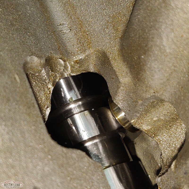
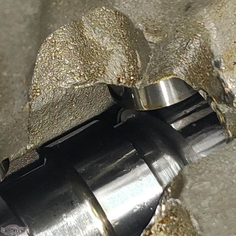
So in fact, when the cam and crank are lined up dot to dot, this is #1 cylinder on the overlap stroke. My buddy confirmed this. Since #1 is on overlap, this means that #6 is on the compression stroke.
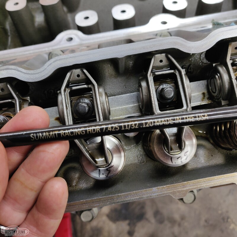
Here you can clearly see that the #1 lifters are not on the base circle.
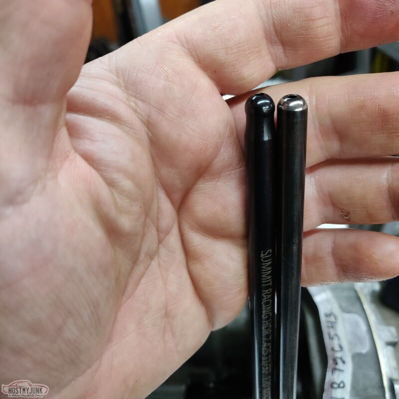
Here is a comparison between the old 7.400" pushrods on the right and the Summit 7.425" pushrods on the left. The tips appear to be a little smaller on the Summit pushrods, so I think their effective length falls somewhere between 7.400" and 7.425". None of this really matters because what I am after is 1.5 turns from zero lash to full torque spec on the rocker bolts.
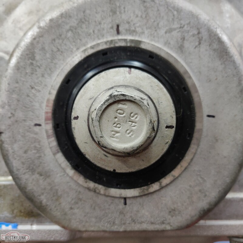
I made some marks on the balancer bolt for reference. I really should have done this before I installed the front cover.
In any case, I started with #6, and the Summit Racing 11/32 7.425" pushrods ended up giving me the best preload.
Then I rotated the engine 90 degrees and followed the firing order for all subsequent cylinders. Once I got the technique down for finding zero lash, the preload readings were pretty consistent with 1.5 turns on the intake valves and about 1.6 turns on the exhaust valves.
I am calling that done and sorted.
Andrew
I started the check preload on #1 cylinder and things didn't add up, because as I tightened the rocker bolt the valves started to open...
Then I remembered that something similar was happening when I did the cam install on the Cougar. A little more digging around and consulting a buddy that knows more about this than I do, and it all started to make sense.
So in fact, when the cam and crank are lined up dot to dot, this is #1 cylinder on the overlap stroke. My buddy confirmed this. Since #1 is on overlap, this means that #6 is on the compression stroke.
Here you can clearly see that the #1 lifters are not on the base circle.
Here is a comparison between the old 7.400" pushrods on the right and the Summit 7.425" pushrods on the left. The tips appear to be a little smaller on the Summit pushrods, so I think their effective length falls somewhere between 7.400" and 7.425". None of this really matters because what I am after is 1.5 turns from zero lash to full torque spec on the rocker bolts.
I made some marks on the balancer bolt for reference. I really should have done this before I installed the front cover.
In any case, I started with #6, and the Summit Racing 11/32 7.425" pushrods ended up giving me the best preload.
Then I rotated the engine 90 degrees and followed the firing order for all subsequent cylinders. Once I got the technique down for finding zero lash, the preload readings were pretty consistent with 1.5 turns on the intake valves and about 1.6 turns on the exhaust valves.
I am calling that done and sorted.
Andrew
The following 2 users liked this post by Project GatTagO:
2ToeRacing (07-15-2023), Summitracing (05-03-2021)
05-02-2021 | 10:55 AM
#235
Thread Starter
Joined: Mar 2003
Posts: 10,222
Likes: 1,511
From: The City of Fountains
The way I had it lined up originally was with #1 at TDC on the overlap stroke, which is why the lifters were not on the cam base circle and why the valves were opening as I tightened down the rockers. I kept the engine in the same location, and simply moved to the #6 cylinder which is at TDC on the compression stroke. Then I picked up the firing order starting from #6.
Andrew
05-02-2021 | 09:15 PM
#236
Thread Starter
Joined: Mar 2003
Posts: 10,222
Likes: 1,511
From: The City of Fountains
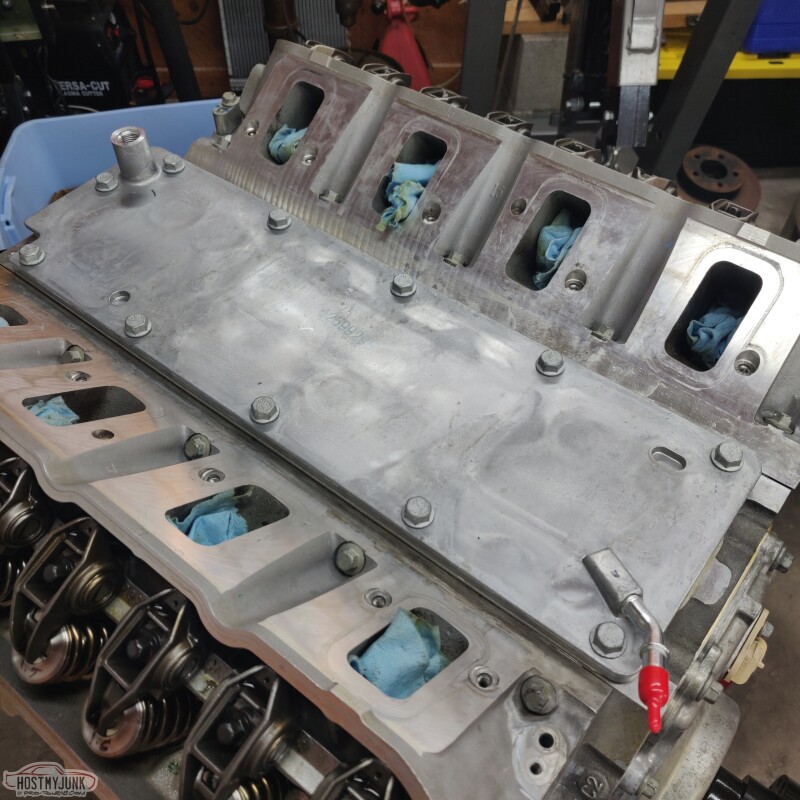
It feels good to be putting stuff back together instead of taking things apart.
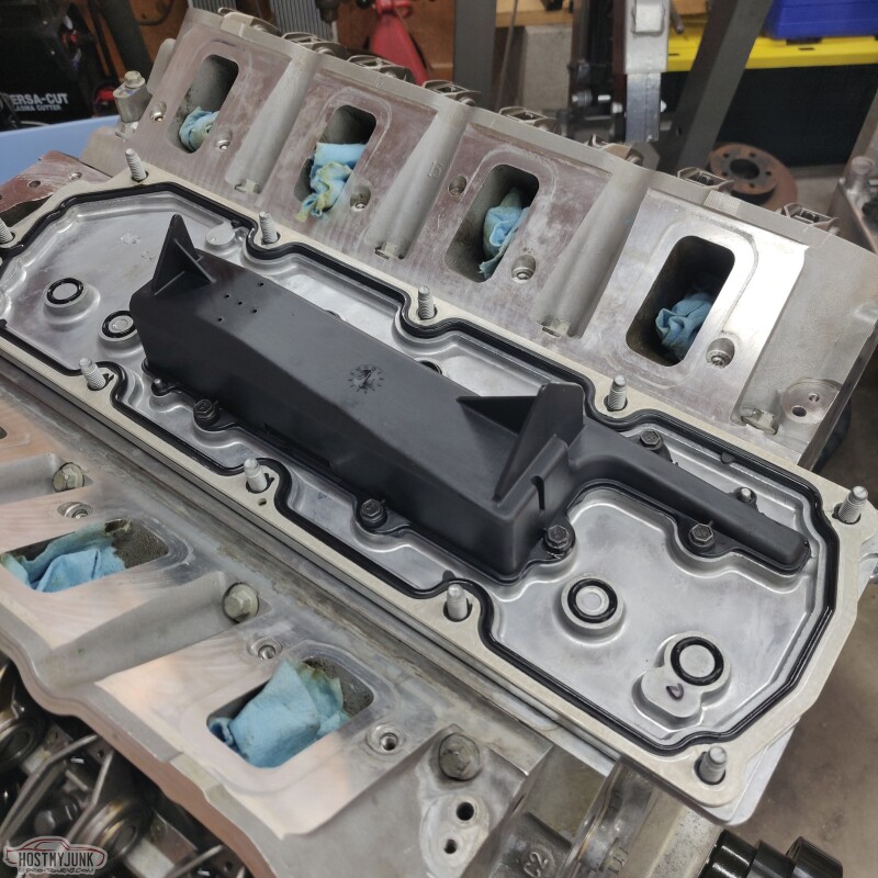
This is a new LS3 style valley cover. I really like the internal baffling to keep oil out of the intake.
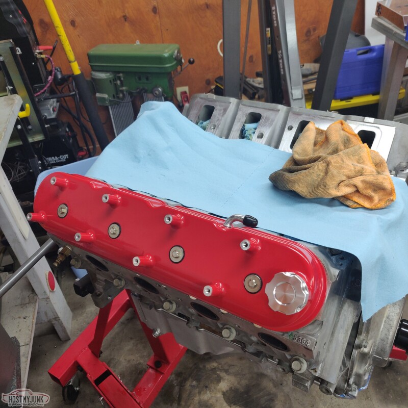
These are the tall Holley valve covers in red. These will add a touch of color and the red is almost a perfect match to the color of the car.
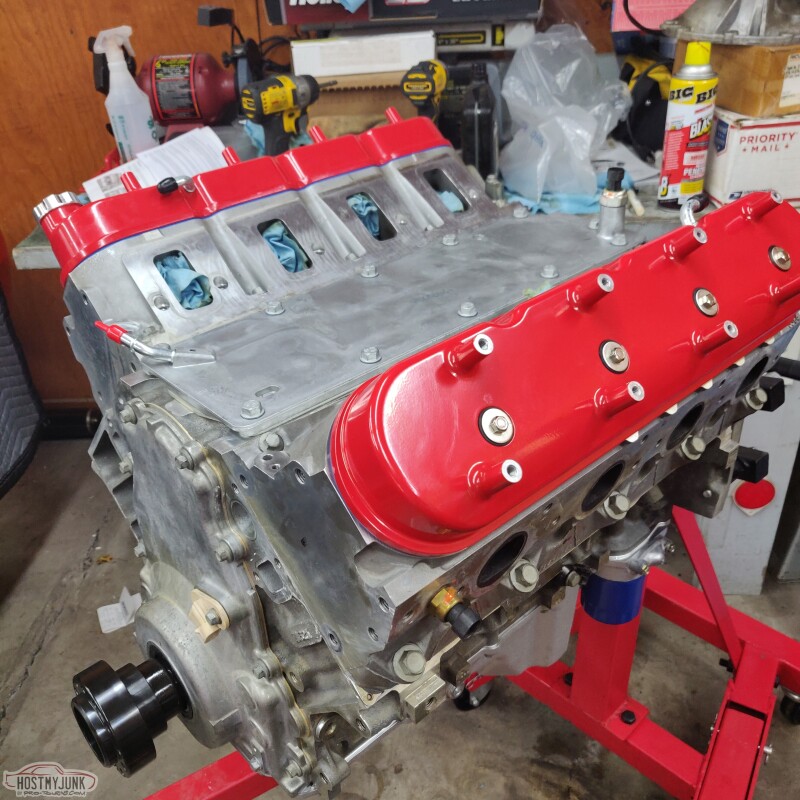
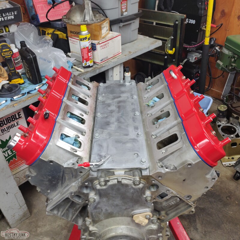
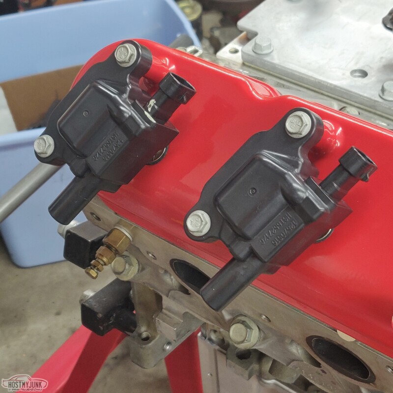
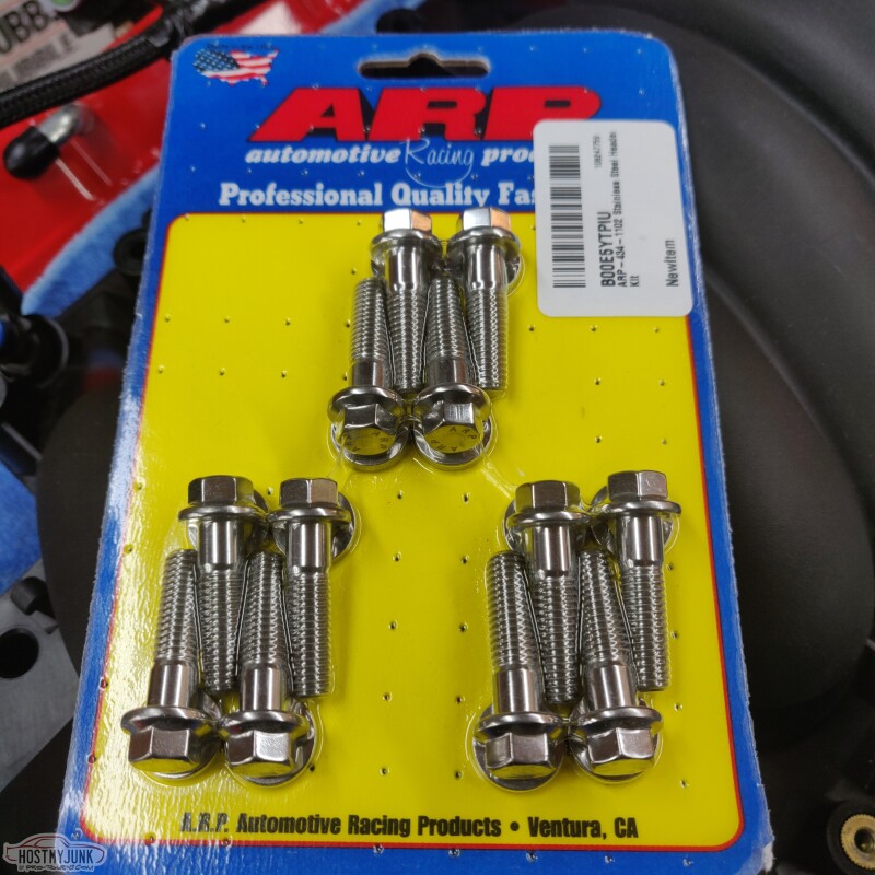
Just cleaned up the coils and will probably get some ARP stainless bots for the coils.
Andrew
This is a new LS3 style valley cover. I really like the internal baffling to keep oil out of the intake.
These are the tall Holley valve covers in red. These will add a touch of color and the red is almost a perfect match to the color of the car.
Just cleaned up the coils and will probably get some ARP stainless bots for the coils.
Andrew
The following 4 users liked this post by Project GatTagO:
05-03-2021 | 09:42 PM
#237
Thread Starter
Joined: Mar 2003
Posts: 10,222
Likes: 1,511
From: The City of Fountains
Ordered a balancer installed tool the other day and it came this morning. So I was able to install the hub of the ATI balancer that comes with the deluxe Holley mid-mount accessory drive kit.
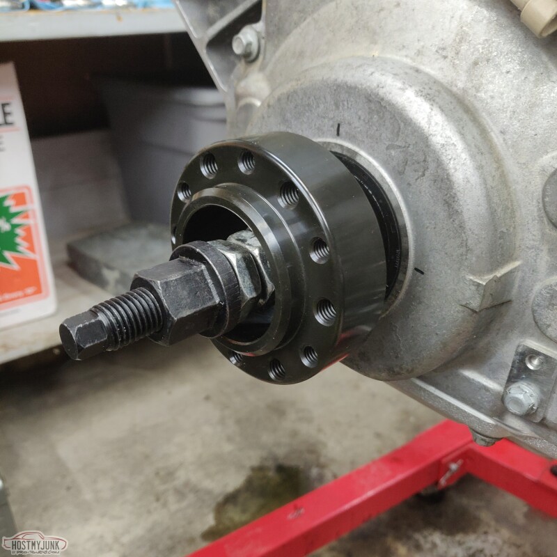
Then the balancer ring gets bolted to the hub. The ATI balancer is a really nice piece.
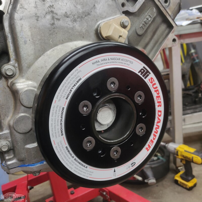
I didn't torque the balancer bolt yet, and I am not exactly sure if it is on all the way. This was as far as it would go with the installer tool. Hopefully it is fully seated.
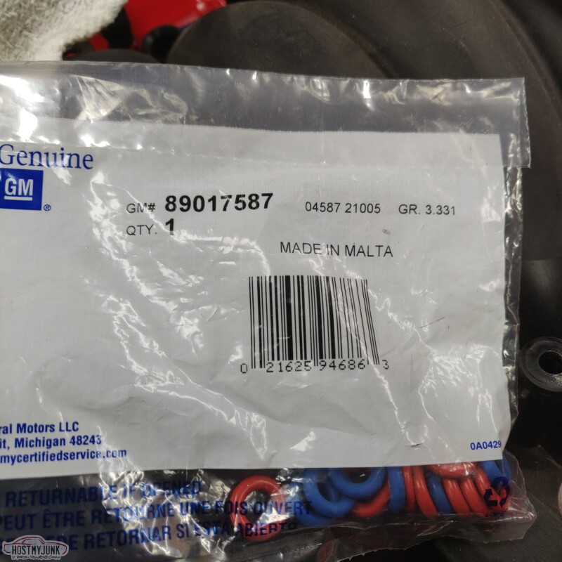
Also got new injector 0-rings...
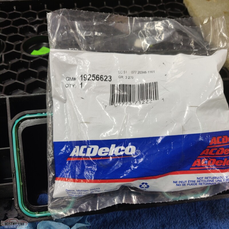
and new intake manifold gaskets. The old ones were in good shape, but I figured it can't hurt.
The intake manifold cleaned up nicely...
Andrew
Then the balancer ring gets bolted to the hub. The ATI balancer is a really nice piece.
I didn't torque the balancer bolt yet, and I am not exactly sure if it is on all the way. This was as far as it would go with the installer tool. Hopefully it is fully seated.
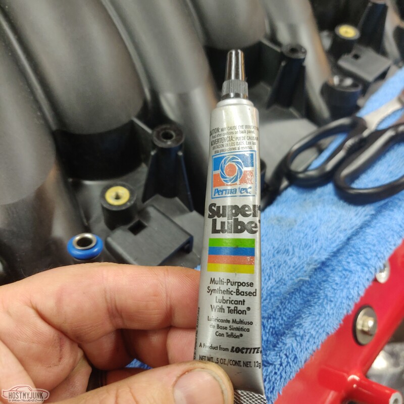
Also got new injector 0-rings...
and new intake manifold gaskets. The old ones were in good shape, but I figured it can't hurt.
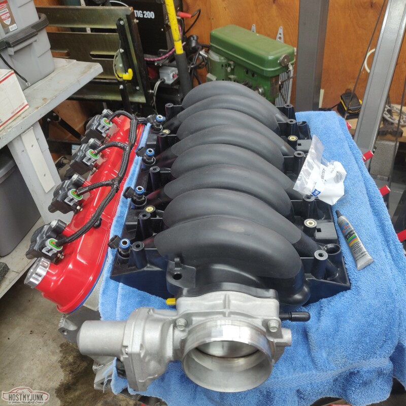
The intake manifold cleaned up nicely...
Andrew
The following users liked this post:
Mikes64 (05-04-2021)
05-04-2021 | 11:57 AM
#238
Thread Starter
Joined: Mar 2003
Posts: 10,222
Likes: 1,511
From: The City of Fountains
This is the lube that I like to use for injector o-rings.
Also received some ARP stainless header bolts.
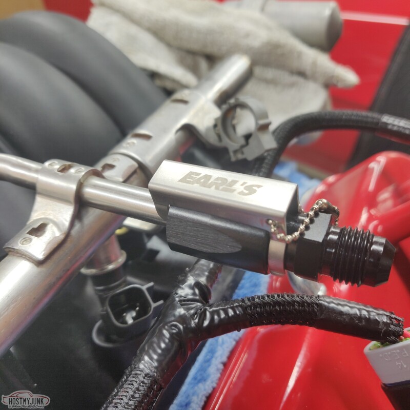
Added an Earl's fuel rail adapter. I like this style because it has metal retaining tabs inside and a secondary retention clip.
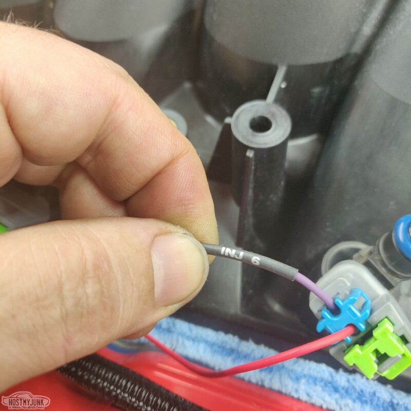
Looks like Holley revised their injector harness and they are now adding heat shrink labels on the cylinders.
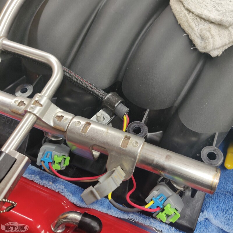
I played around with different routing for the injector harness and I like something like this, on the inside of the rail. I have some different P clamps coming to secure the harness to the studs that hold the fuel rail.
I didn't like how the injectors had about 4 inched of exposed wire, so I used some Tessa harness tape to protect them a little more. Plus this makes the wires blend in.
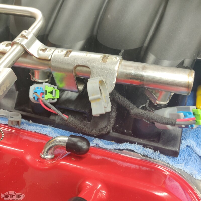
The coil harness will be retained by the little clips on the rails. I have an assortment of those clips on the way.
Andrew
Also received some ARP stainless header bolts.
Added an Earl's fuel rail adapter. I like this style because it has metal retaining tabs inside and a secondary retention clip.
Looks like Holley revised their injector harness and they are now adding heat shrink labels on the cylinders.
I played around with different routing for the injector harness and I like something like this, on the inside of the rail. I have some different P clamps coming to secure the harness to the studs that hold the fuel rail.
I didn't like how the injectors had about 4 inched of exposed wire, so I used some Tessa harness tape to protect them a little more. Plus this makes the wires blend in.
The coil harness will be retained by the little clips on the rails. I have an assortment of those clips on the way.
Andrew
The following 2 users liked this post by Project GatTagO:
G Atsma (05-04-2021), will69camaro (05-04-2021)

The following users liked this post:
Project GatTagO (05-05-2021)
05-05-2021 | 12:00 PM
#240
Thread Starter
Joined: Mar 2003
Posts: 10,222
Likes: 1,511
From: The City of Fountains
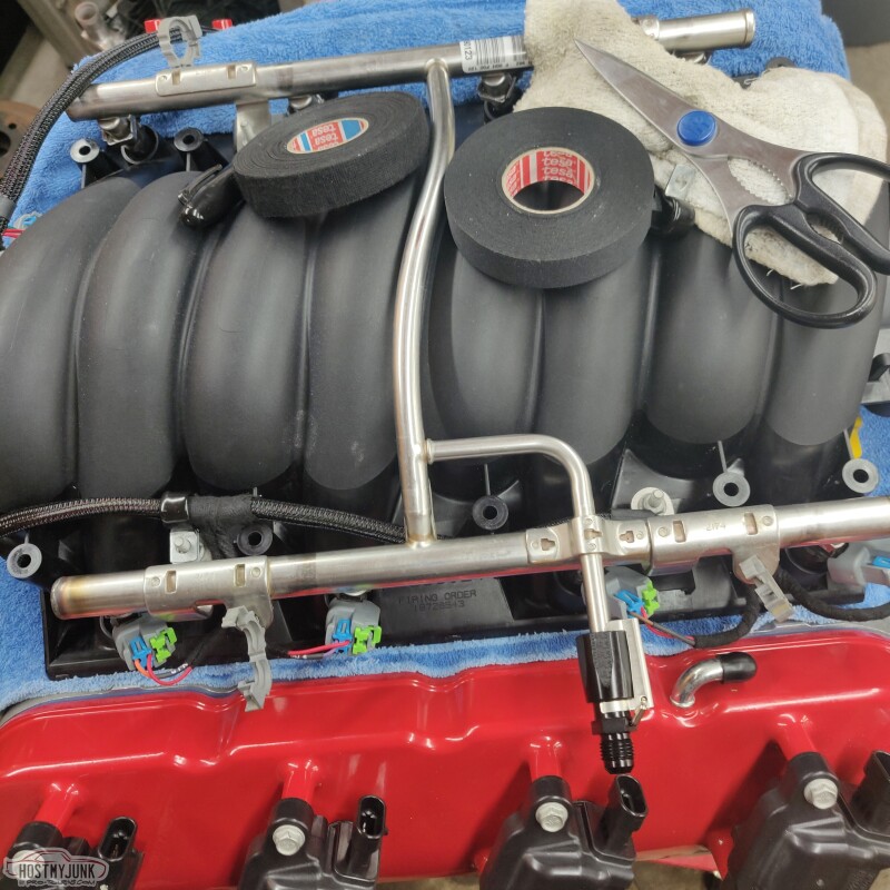
If you look carefully those rolls are not the same. The one on the right is more like cotton friction tape. The one on the right is thinner and has a soft feel to it. Tessa calls it "Mercedes/BMW/VW harness tape."
Andrew
Andrew