When you click on links to various merchants on this site and make a purchase, this can result in this site earning a commission. Affiliate programs and affiliations include, but are not limited to, the eBay Partner Network.
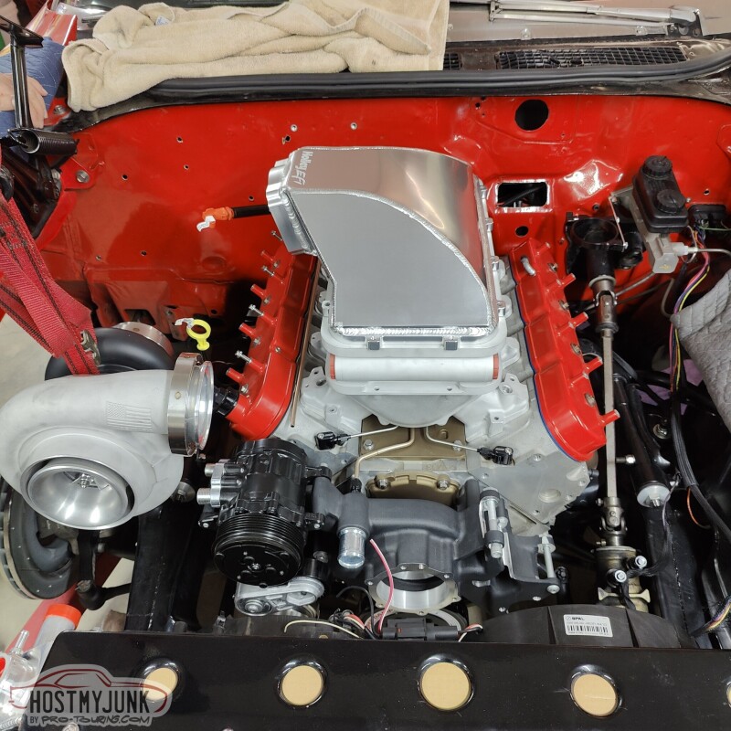
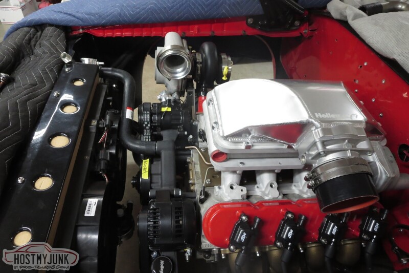
While waiting for a few small parts to arrive we decided to mock up a few intake arrangement options. My original idea was to have a side entry lid facing the passenger side. This arrangement will make it a challenge to snake the charge pipe from the compressor outlet to the throttle body, but I think it can be done.
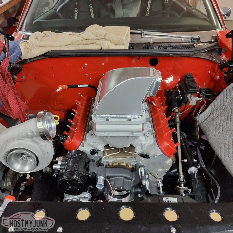
This is an alternative side entry. Obviously the charge pipe will be longer, but the path should be easier to lay out.
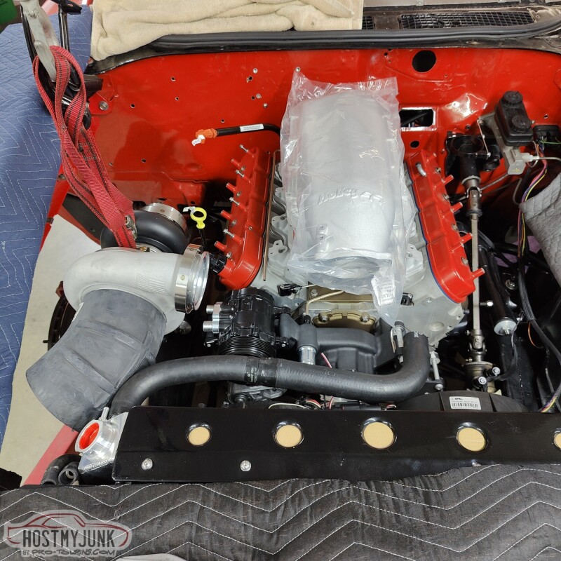
This is the front entry options. Again snaking the charge pipe will be a challenge, plus, I am pretty sure the peak of the lid will hit the hood.
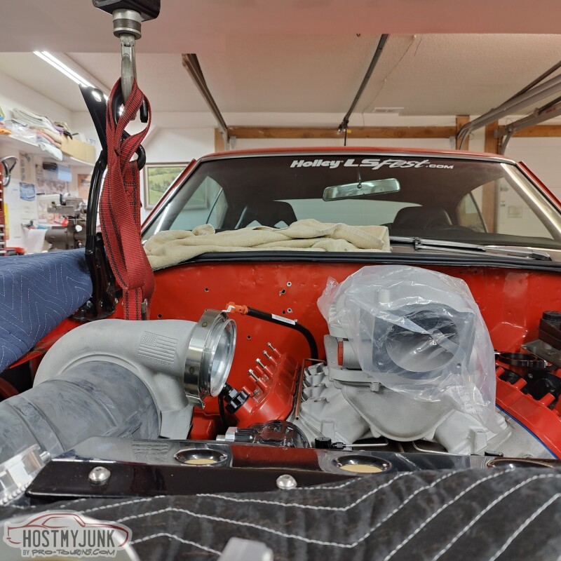
Front view of the front entry option.
You'll have to use your imagination and add another 3" to the front of the intakes for the throttle body.
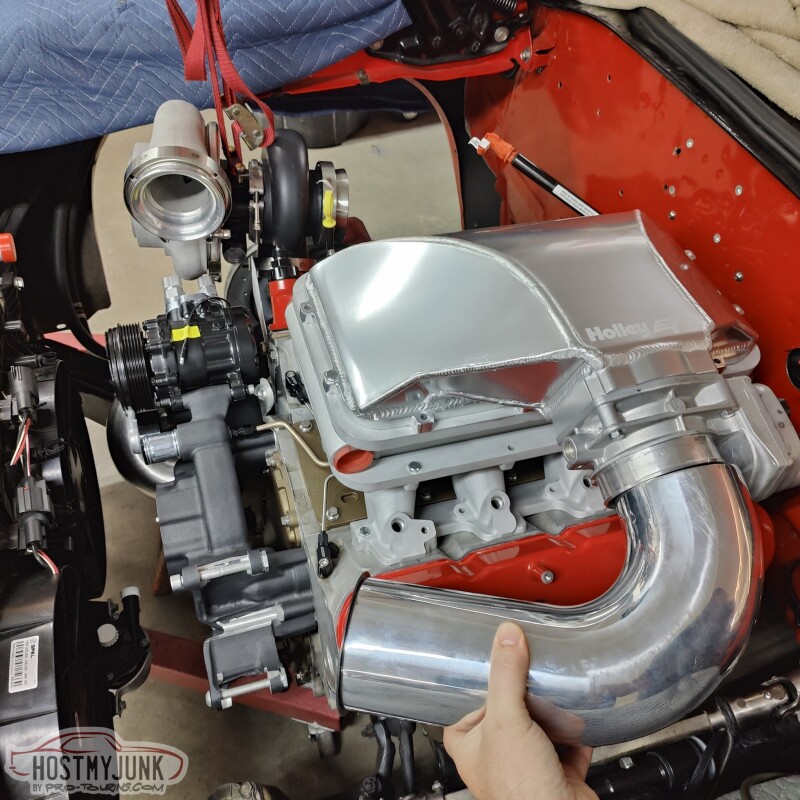
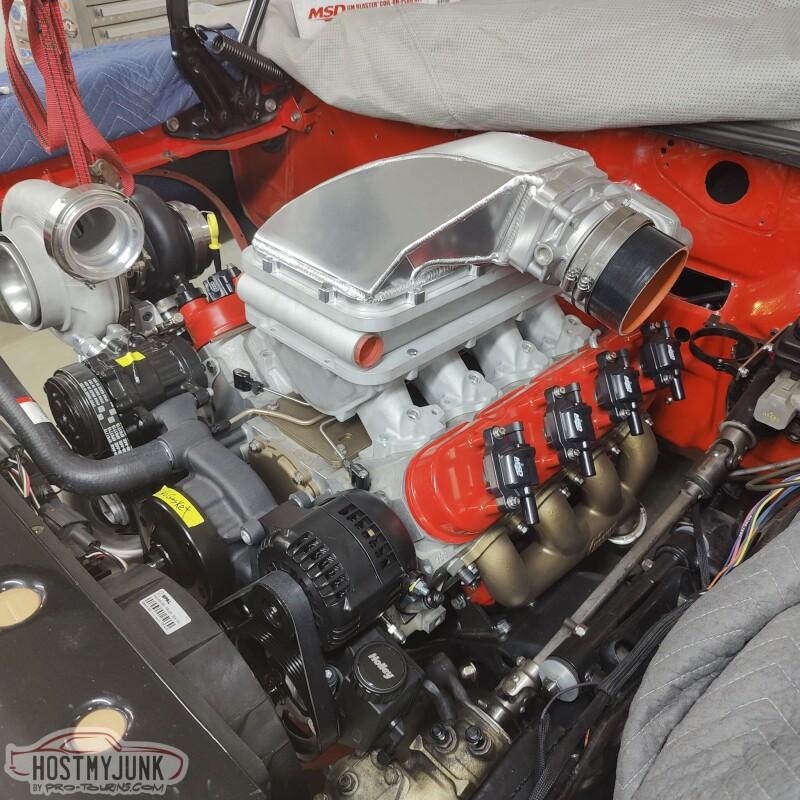
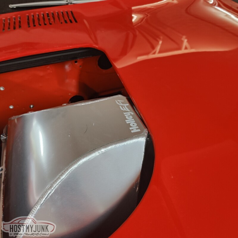
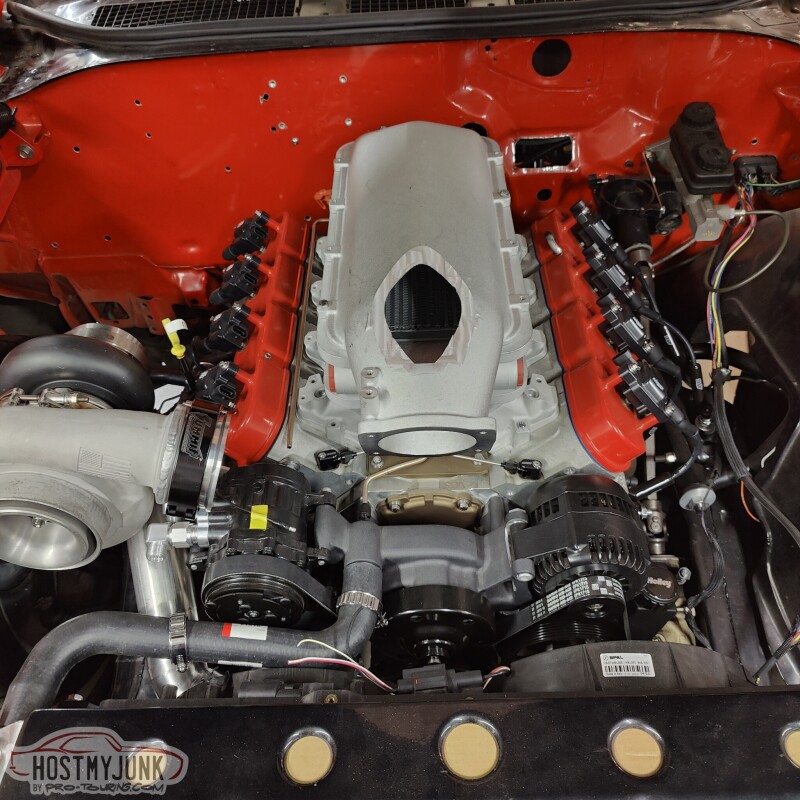
We chose to do this intake orientation, just to make the plumbing path not so arduous. There will be a simple silicone coupler at the throttle body. The rest will be fitted and welded together, with the V-band at the compressor discharge. Still unsure about the hood clearance, but that is a problem for future me.
You can also see the pump for the A2W intercooler mounted to the fan. The Volt actually had a little water pump mounted in that location.
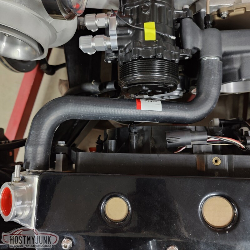
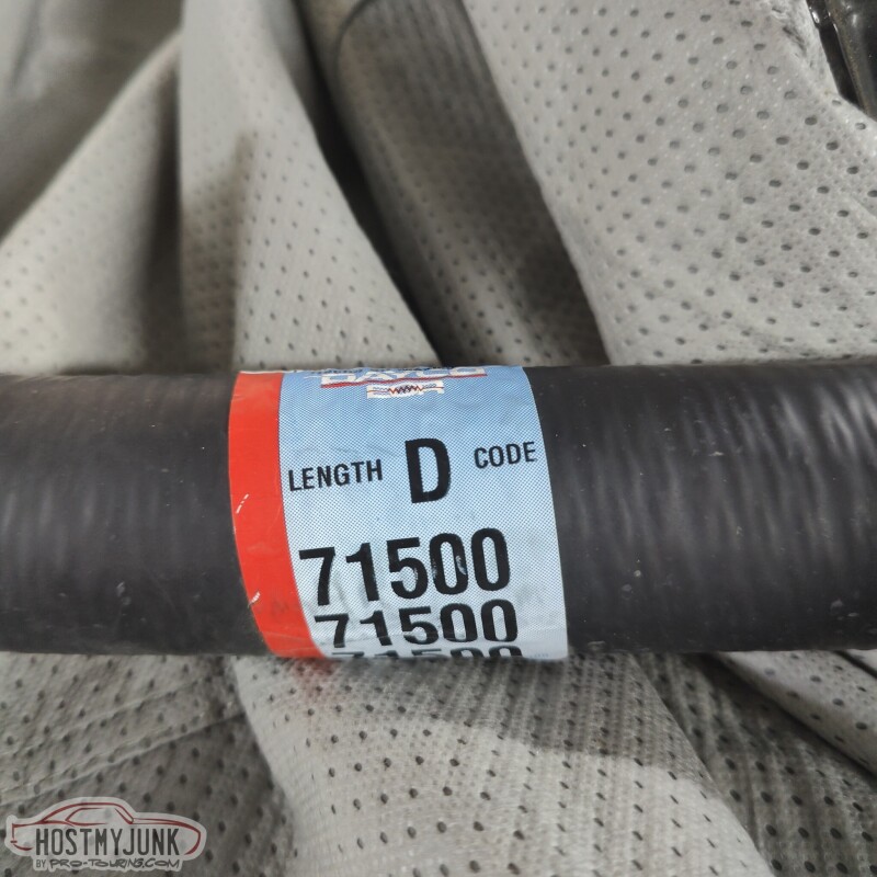
I also got and installed the 90 degree fittings from Vintage Air. These will allow us to go straight down with the AC hoses and keep it neat and tidy. We also got the upper radiator hose sorted out with a Dayco D71576.
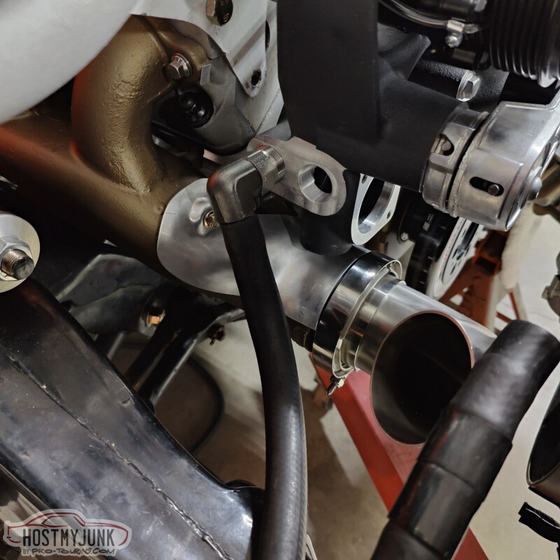
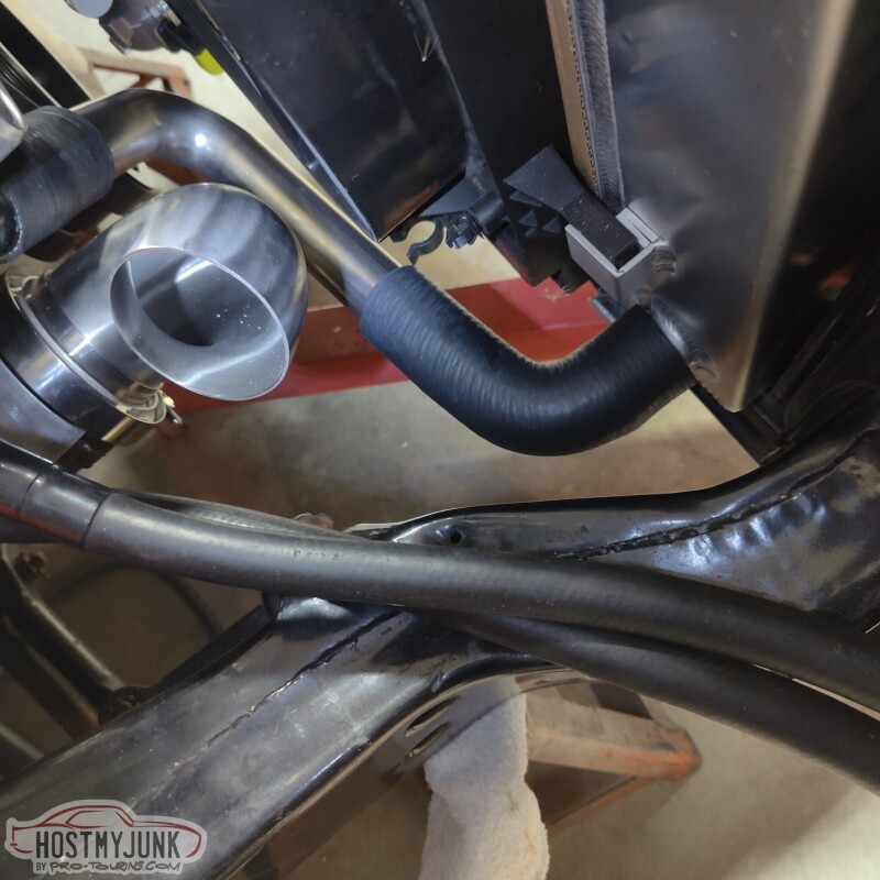
One of the Earl's 90 degree swivel heater hose adapters showed up. These will route the hater hoses away from the up-pipe to the turbo. I will probably add high heat sleeving over both of the heater hoses, just in case.
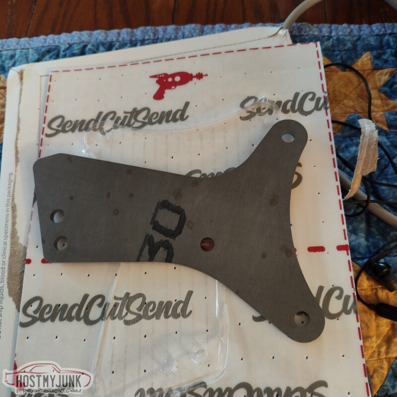
Lastly, Vic and I finalized the design of the turbo support bracket and it was uploaded to Send Cut Send to be cut out. It will be made from .190" 4130 steel.
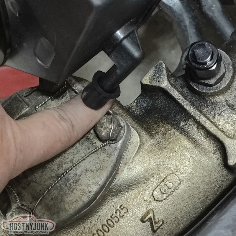
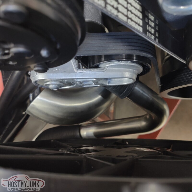
Had another, fairly productive day with Vic today. We started putting the rest of the Holley mid-mount system on the front of the engine, so that we didn't have any surprises down the road. Everything went together pretty well, but this power steering return might become a problem. That's a problem for Future Me...
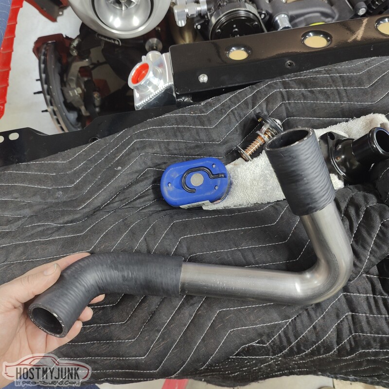
I am not sure where Vic got it, but he has the whole Dayco radiator hose catalog as a PDF. I sat down and looked up hoses that were 1.5" I.D. which matches the lower radiator and the thermostat housing hose size. I found this gem. It has 3 usable, tight 90 degree bends and plenty of straight section, and all of it is 1.5" I.D..
I had also ordered some 1.5" stainless, tight bend J-pipes, one with a 90 degree bend and the other with a 120 degree bend. Both were from Vibrant performance.
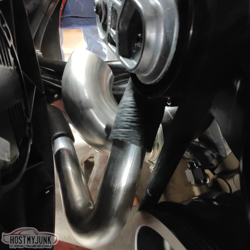
This is the configuration that we chose to do, in conjunction with a swivel thermostat housing.
In each picture it looks like it is tight in certain areas, but in reality, there is a solid 3/4" of clearance between all critical areas.
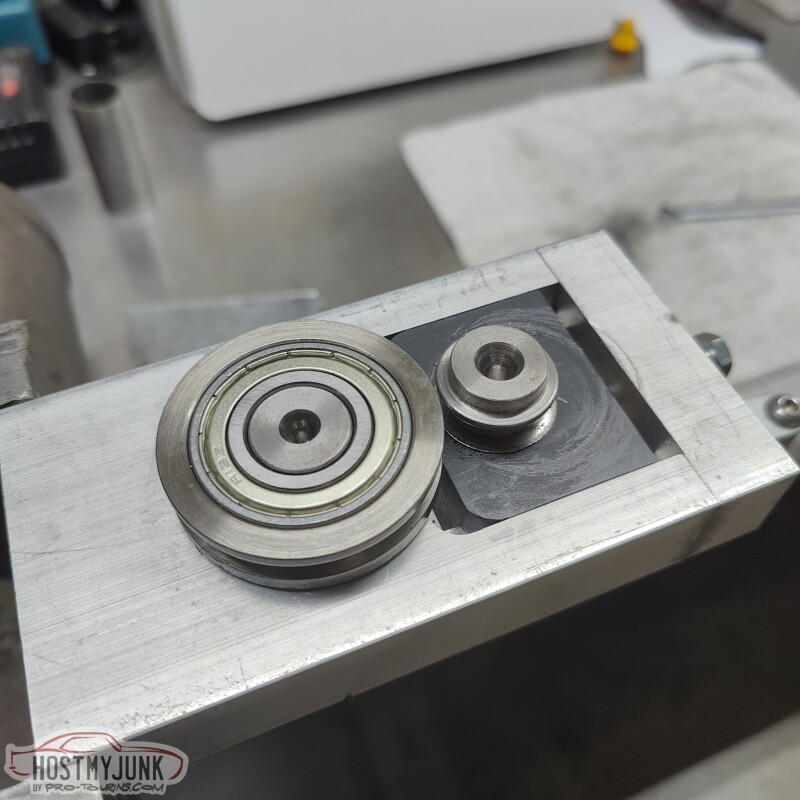
Vic had this nifty, home-made bead rolling tool.
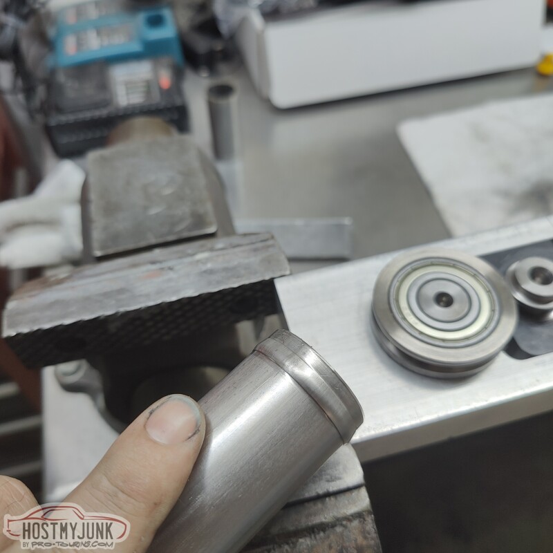
It took a little effort, but we got a nice bead at each end of the tube.
This is the final shape of the lower radiator hose. Murray clamps will be used everywhere on the engine.
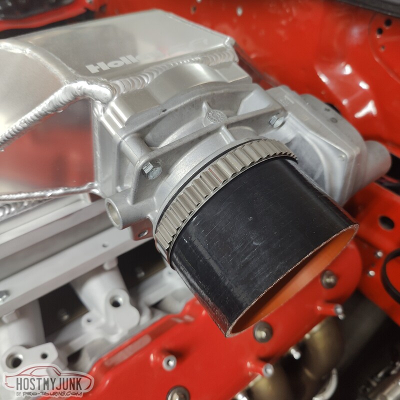
Like this one that I got for the intake pipe.
It is finally starting to look like something...
The turbo bracket that was made by Send Cut Send should be here on Wednesday. My friend Tom is also coming for a visit from Alabama and our mission is to get the new Ford 9" from Quick Performance installed. I will also get my new rear tires on Wednesday. Should be interesting!
Probably not what you want to do with a new pump, but you could probably cut that plastic nipple off, smooth out the reservoir and put in an AN fitting as long as you can get the nut on the inside. I put this one in my F body pump for a hydroboost return years ago and its worked flawlessly, probably close to 50k miles now.
Probably not what you want to do with a new pump, but you could probably cut that plastic nipple off, smooth out the reservoir and put in an AN fitting as long as you can get the nut on the inside. I put this one in my F body pump for a hydroboost return years ago and its worked flawlessly, probably close to 50k miles now.
Thanks for the suggestion!
Someone on the Chevelle forum had the same issue and ended up doing this:
My friend Blake is a Solid Works wizard and we designed this bracket to support the turbo. I uploaded the file to Send Cut Send and less and a week later I have the part. The holes were left a little undersized on purpose.
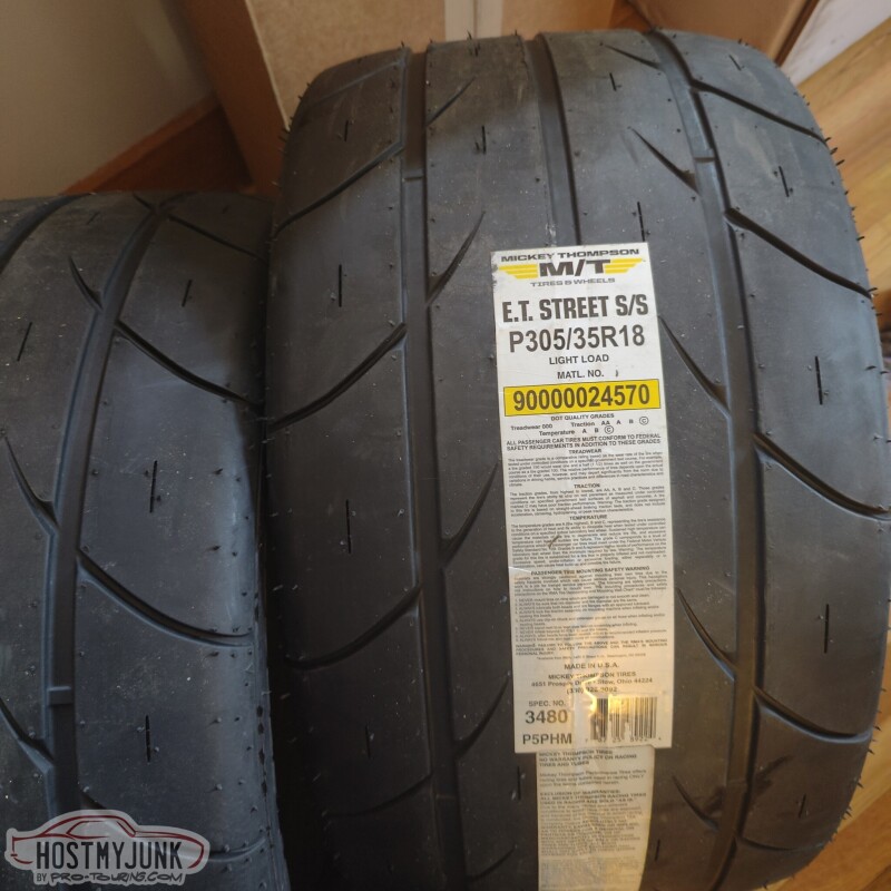
Today the tires showed up. Hopefully they fit (they should according to my calculations).
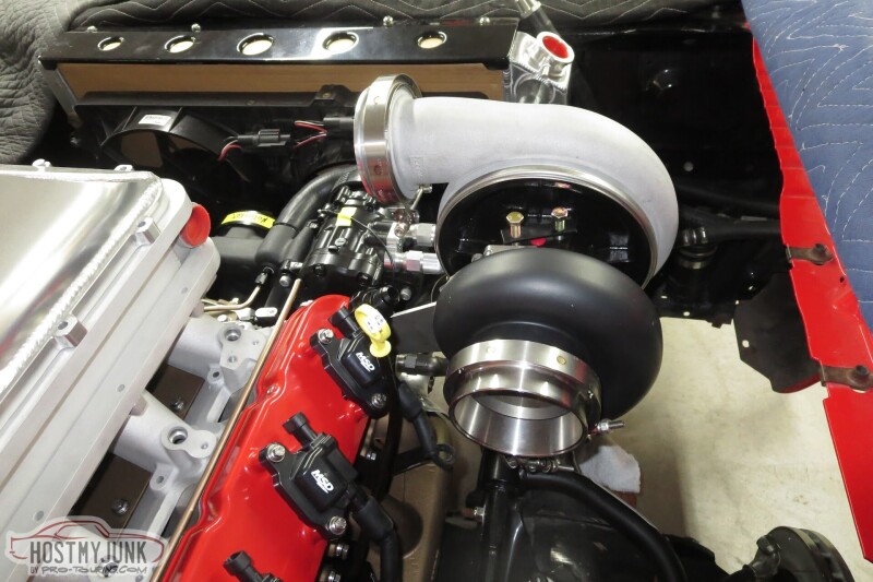
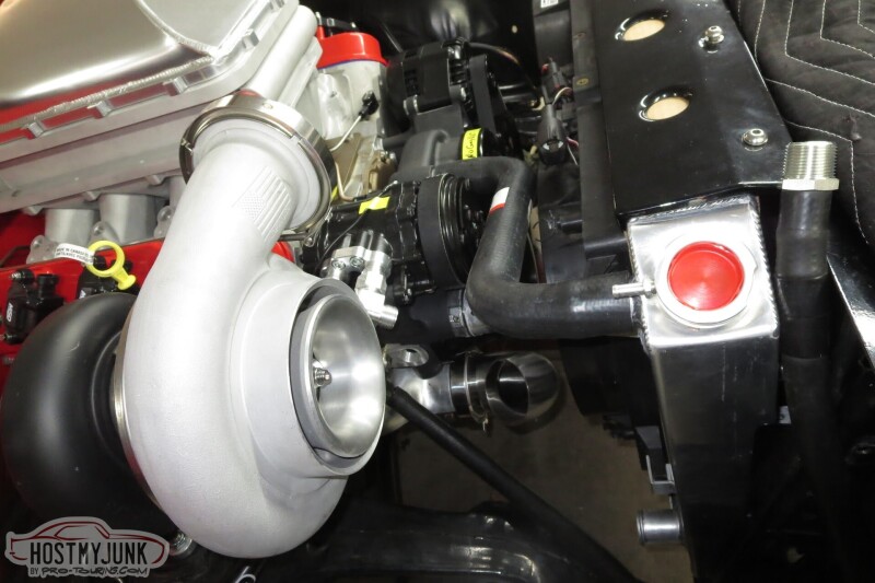
I took the bracket to Vic and today he sent me these pictures.
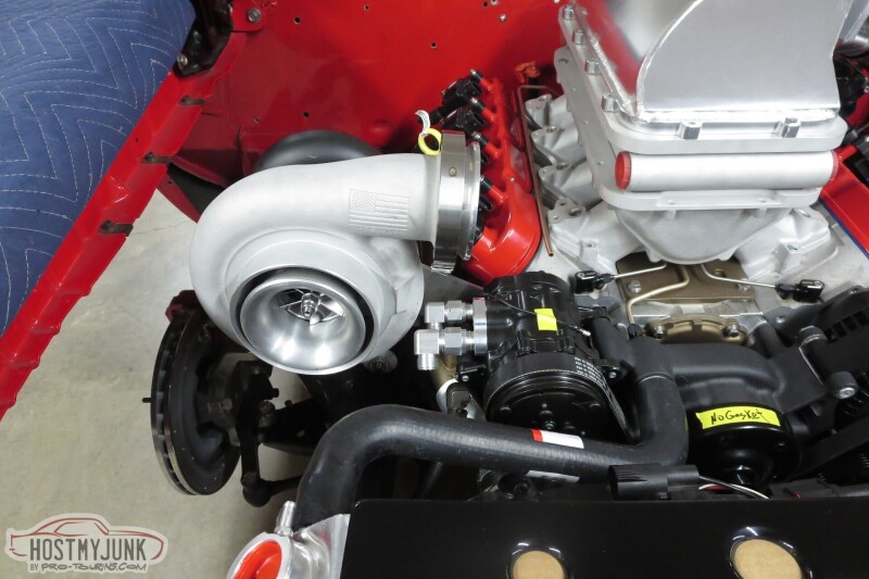
Pretty excited to finally see the turbo installed without an engine hoist holding it up!
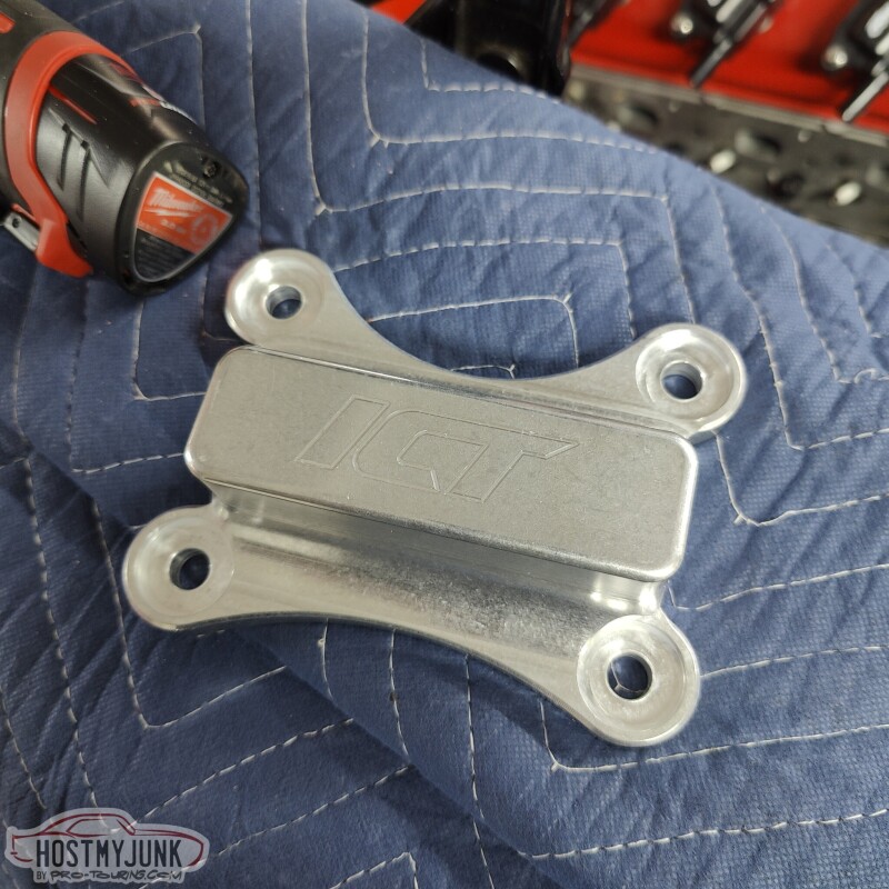
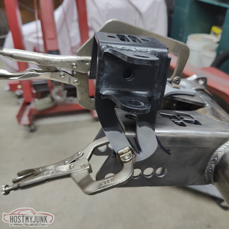
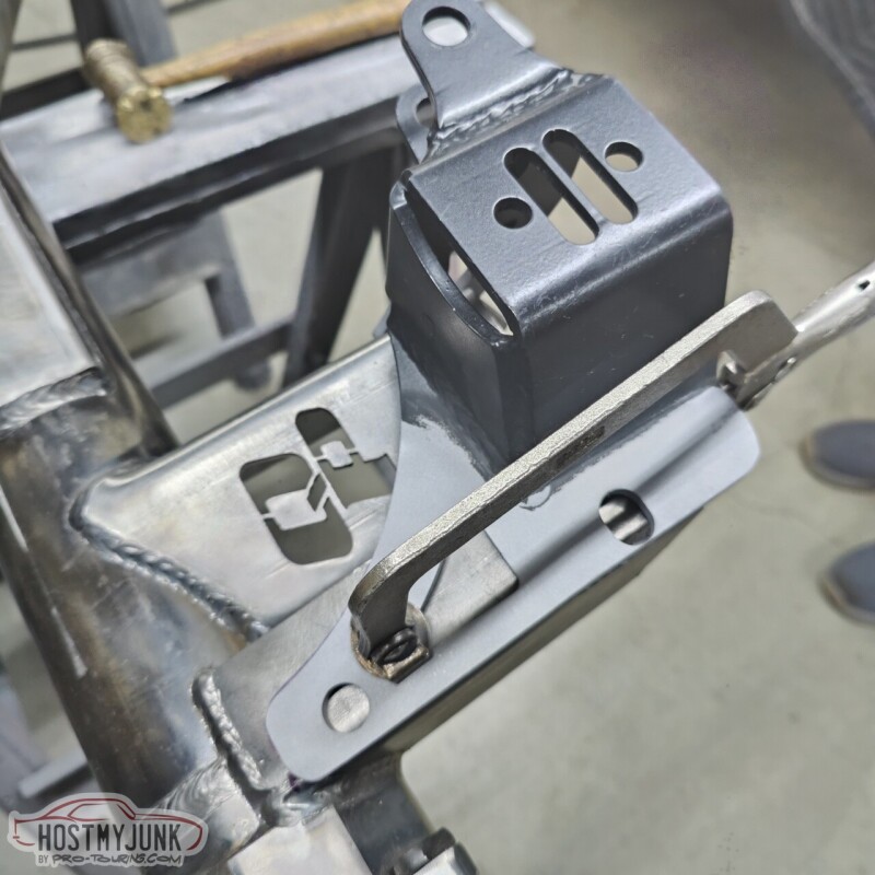
I consulted with Todd, who works for Holley and is a great engineer, and he suggested that the poly mount may no do well being so close to the exhaust manifold. So I got these billet aluminum mounts from ICT.
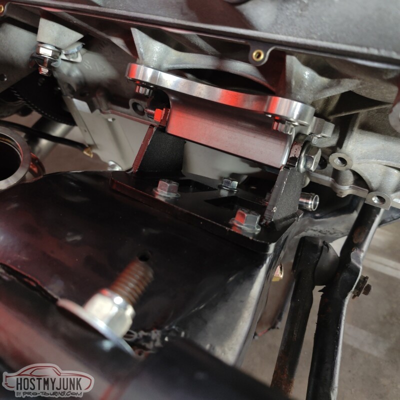
I got a pair, but I only used one on the passenger side, and it fit perfectly, after we milled .050" off each end to give them enough wiggle room between the ear of the frame stands.
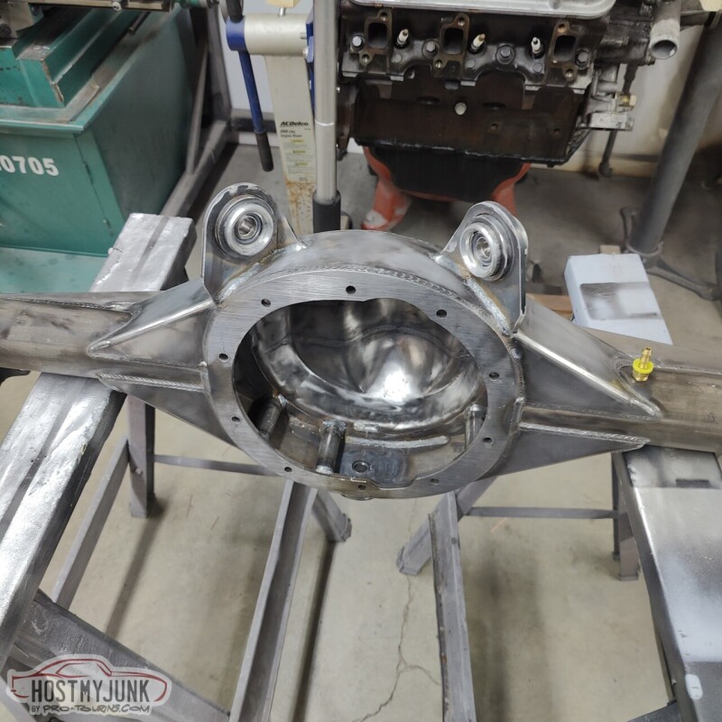
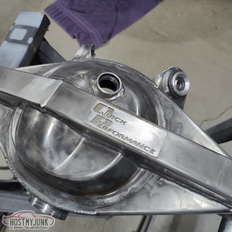
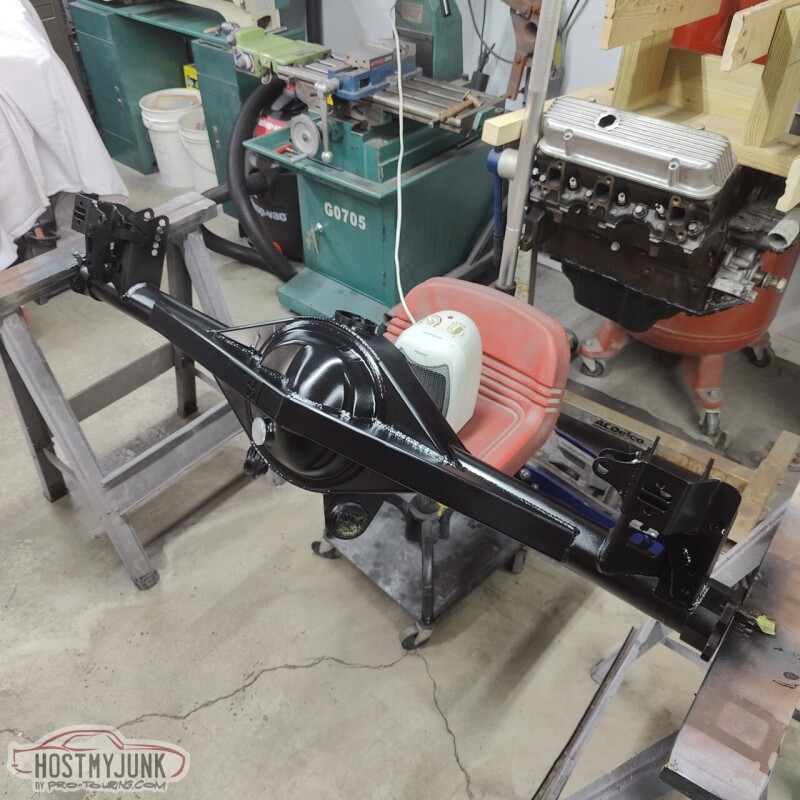
My friend Tom visited me from Alabama and our goal for his visit was to mock up and ultimately install the Quick Performance 9" rear end. I knew that things were not going to just bolt together because the brackets on the QP rear are not exactly the same as an original 12 bolt, plus I ordered mine with multiple holes on the lower control arm bracket.
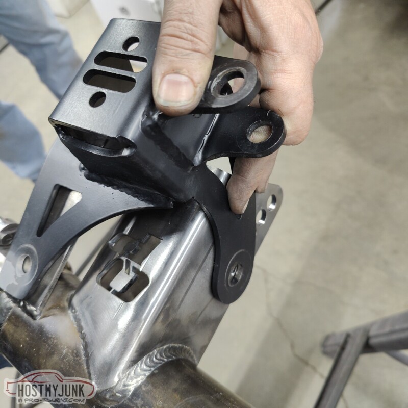
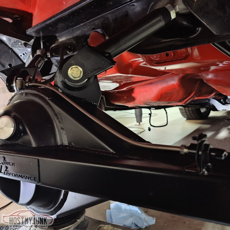
You can see in this picture how the Ridetech coilover bracket is designed to bolt to the original shock mount and then a tab comes around and gets bolted with the lower control arm bolt.
The bracket was trimmed to allow the use of all the holes on the lower control arm bracket.
The bracket was also trimmed on the side to remove a little excess material where it rests against the shock mount on the QP housing.
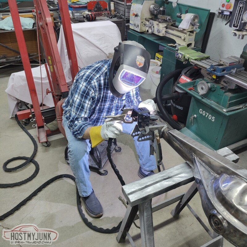
Then Vic went to work doing his thing...
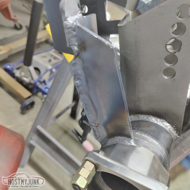
Here is the final result, with the Ridetech coilover bracket fully welded to the QP housing.
We also pressed the Ridetech R-joints out of the old 12 bolt and into the QP upper control arm ears. Ridetech included a tool to make this process very straightforward.
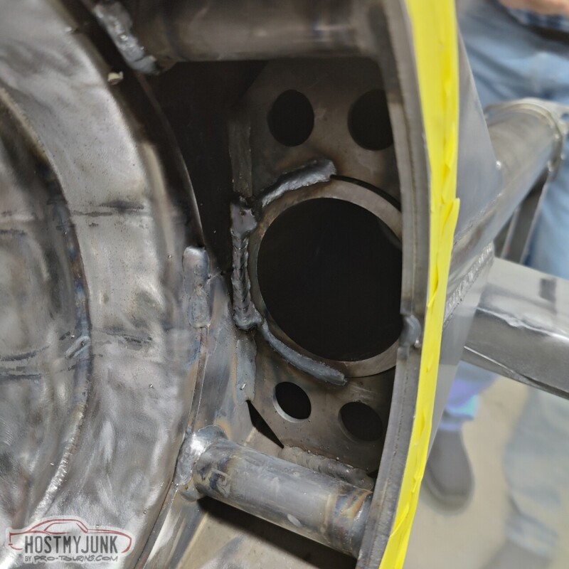
When I ordered the QP housing I checked all the boxes for the extra internal gussets...
..and the back brace. I also chose the fill and the drain option.
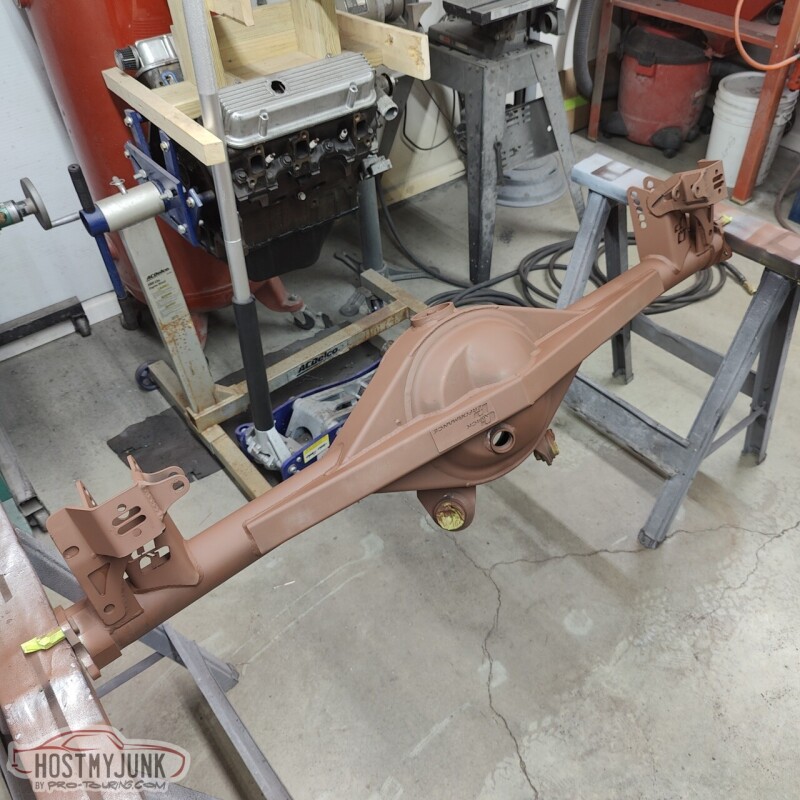
After the Ridetech coilover brackets were welded, I went over the whole housing and softened up all of the hard edges on the brackets and Tom shot a coat of Rustoleum primer.
..followed by a couple of coats of Rustoleum semi gloss black.
The most expensive tires I have ever purchased showed up as well. If I can get two seasons out of these I'll be happy.
Had them mounted and balanced at my local Discount Tire. They have taken good care of me with the tires for the Cougar.
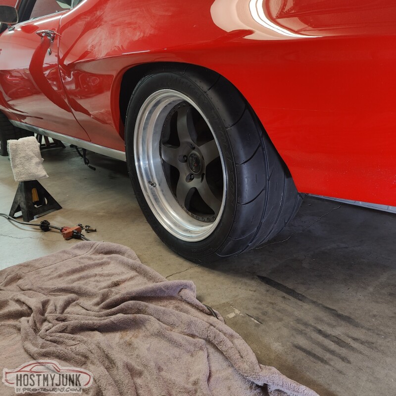
The fit in the wheel wells is pretty good. This rear end was ordered to be 1/2" narrower on each side, but it almost feels like they narrowed it 1" per side. I have not compared the width to my 12 bolt yet. Using a 1/2" spacer will put the tire dead center in the wheel wells.
This is with the 1/2" spacer, so the new tires are good to go.
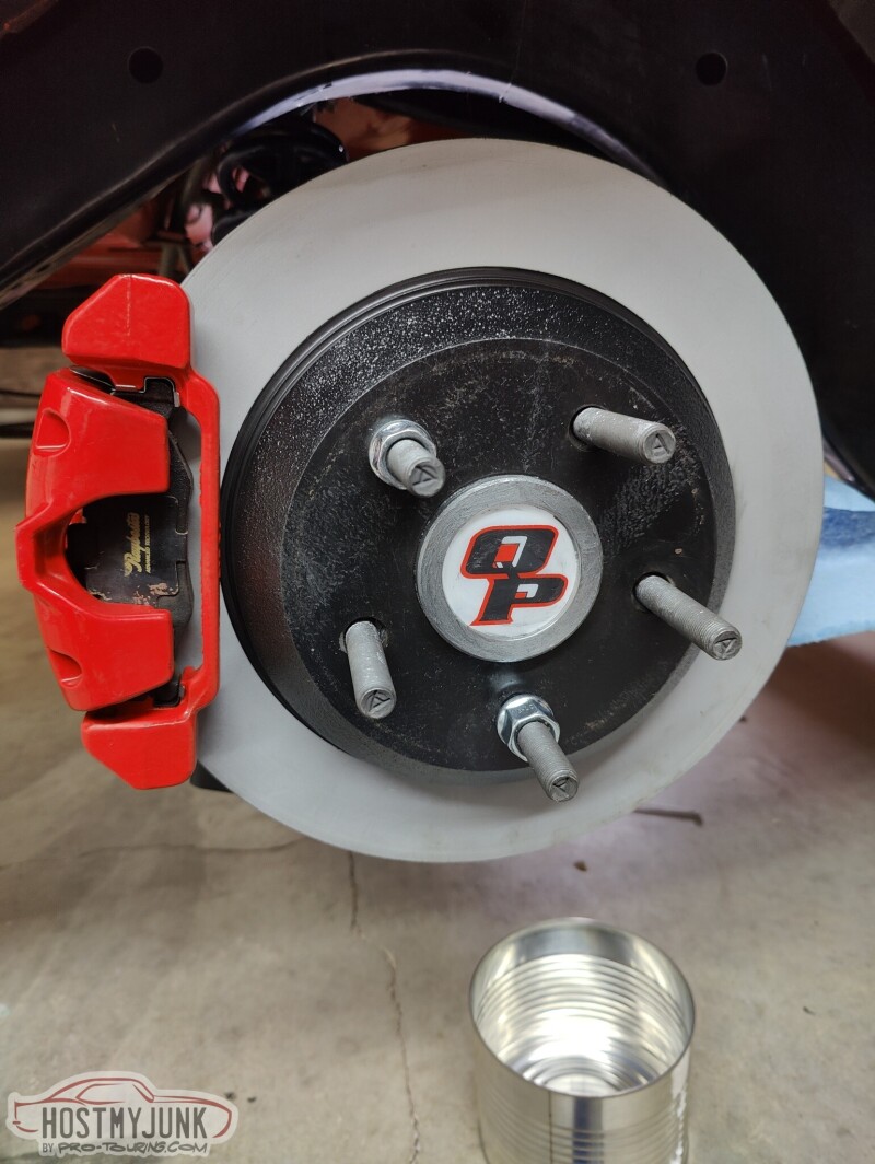
Made a little progress today ahead of the blizzard that is going to hit tomorrow morning. Vic bead blasted the rotors to get the surface rust off and shot then with a coat of paint. I cleaned up the calipers and bolted everything together.
Some of you may notice that the caliper is on the back side of the rotors. These are brakes from a 98-2002 F-body and normally the caliper is on the front side of the rotor. The reason for the swap is that we messed up when we pressed the bearings on the axles. I accidentally installed the caliper brackets on the wrong sides. Instead of battling with pulling the bearings off and possibly damaging something, we decided to move the calipers to the rear. I swapped the calipers side to side so that the bleeder is at the top.
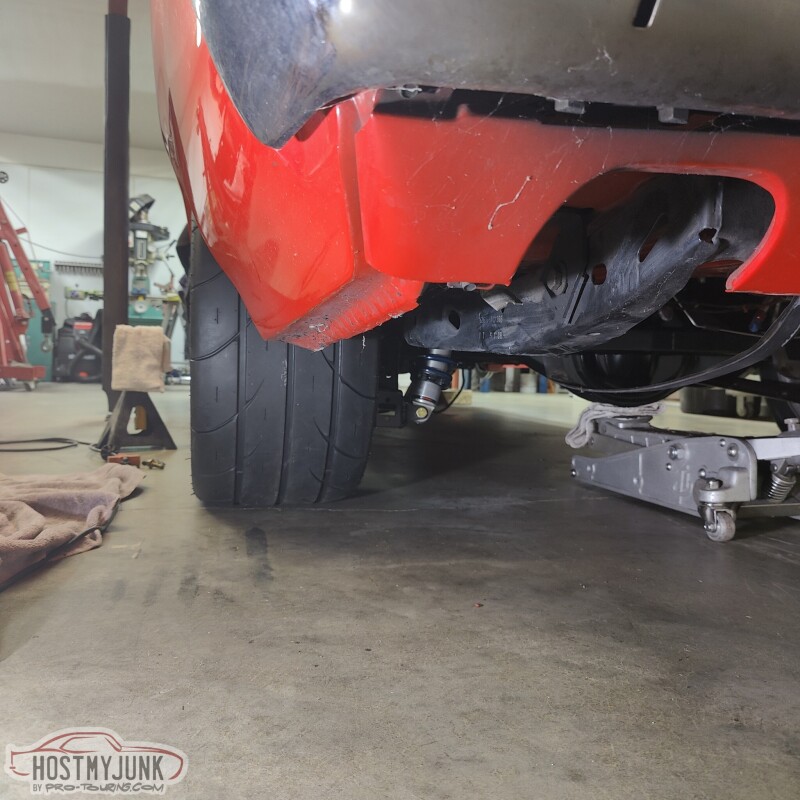
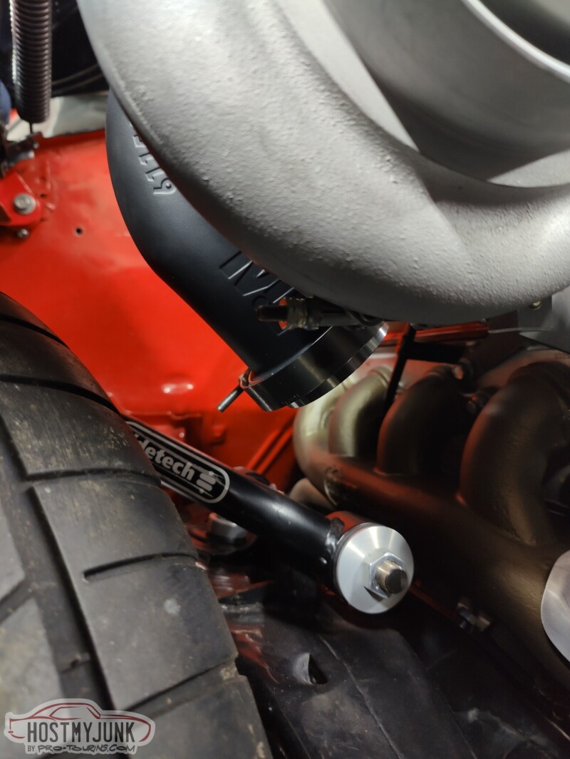
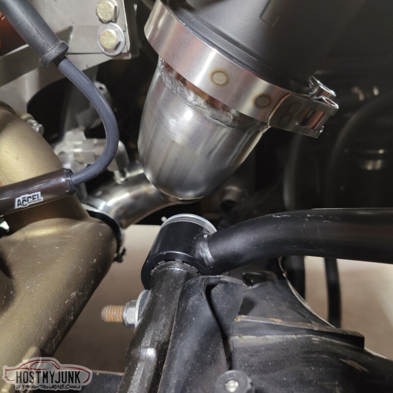
We put the car down on the ground in the front to check clearance with the suspension. The up-pipe is no pictured, but is about 1-1.5" away from the bushings. The Ridetech control arms use deleon bushings and I plan to wrap the up-pipe and also put a woven sock over it. I don't expect any issues.
I got these nifty clamps from Australia, made by a company called SS Customs.
Progress has slowed down a little bit, but I did manage to completely finish the rear end installation. The rear was installed, but I needed to make some new brake lines from the center, out to the calipers.
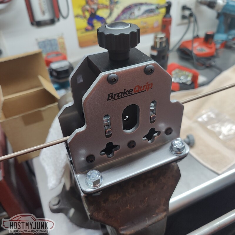
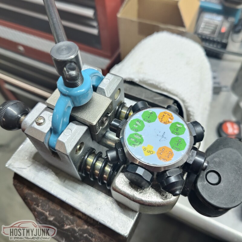
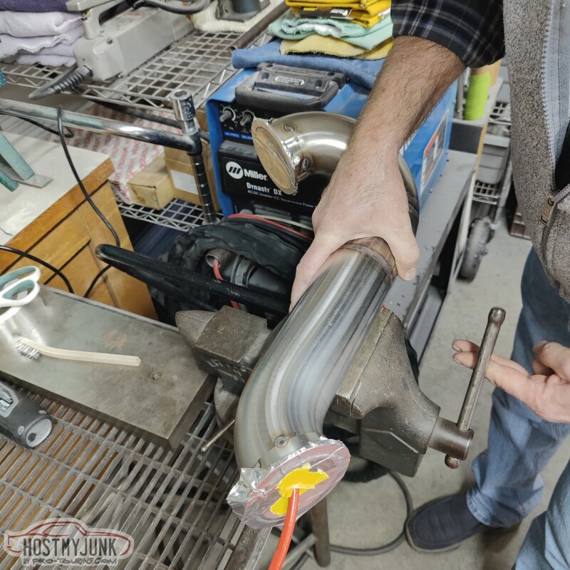
A while back I got this tubing straightener.
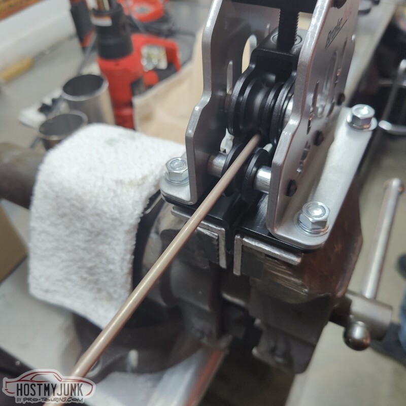
It mounts in a vise and does a really nice job of turning a coil of NiCopp brake like into a straight piece.
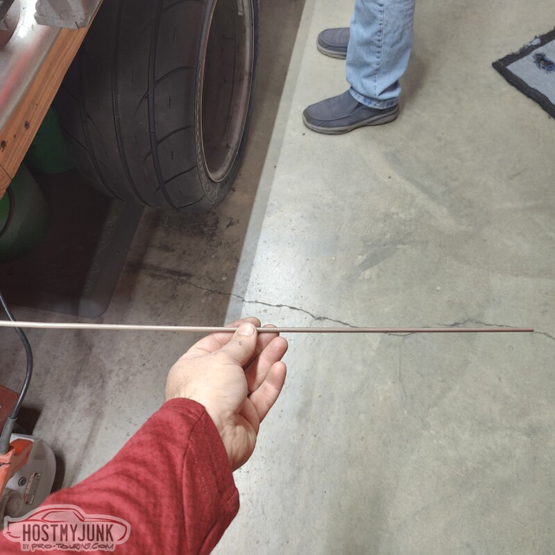
Here is the result after a few minutes of getting it worked through the rollers. I suggest straightening the tube before cutting it because then you can use the coil to manipulate the tubing through the rollers.
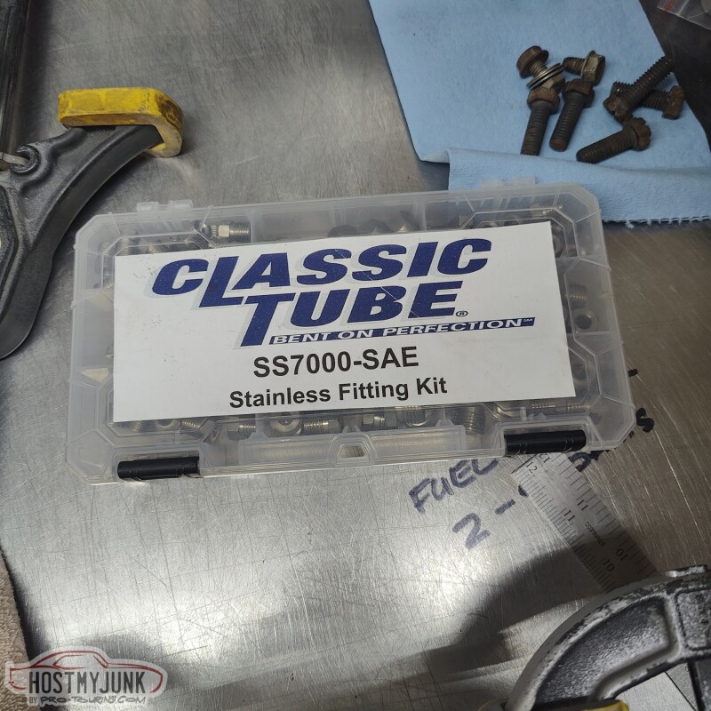
I also picked up this little kit that has a variety of stainless tube nuts for all of the common SAE flares.
Vic had this awesome flaring tool and it worked really well.
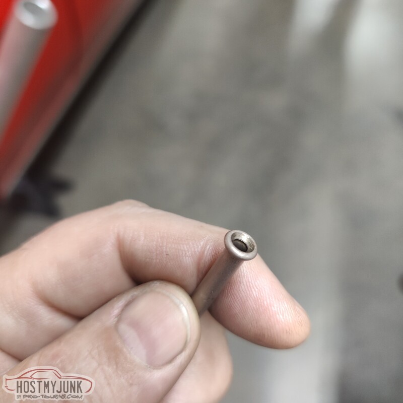
The double flares turns out perfectly.
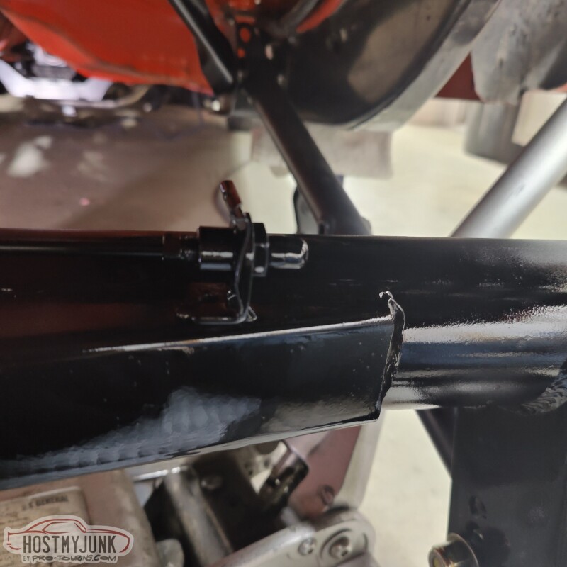
I reused these little brackets and adapters from the old rear end. It is a SAE to AN-3 adapter. We welded it to the housing and I hit it with a little paint. The little brake like wasn't the actual brake line. It was just a piece that I made so the threads would not get painted.
For the center hose support I cut and bevelled a short piece of threaded hex stock and then welded it to the housing.
In other sad new, we trimmed some bracing on the underside of the hood, and it still doesn't close...
With Christmas behind us, Vic and I are making slow, but steady progress.
Today he was able to fully weld the up-pipe that goes between the Hooker exhaust manifold and the turbine inlet. He back-purged the pipe to avoid any "sugaring" on the inside.
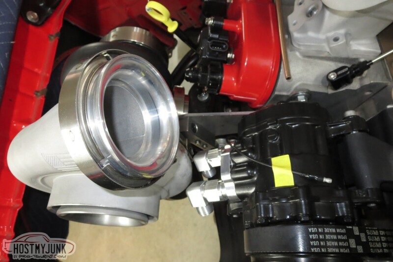
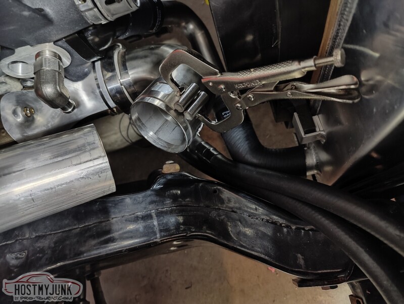
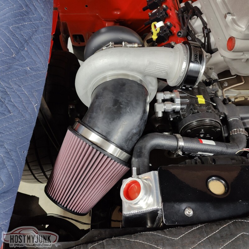
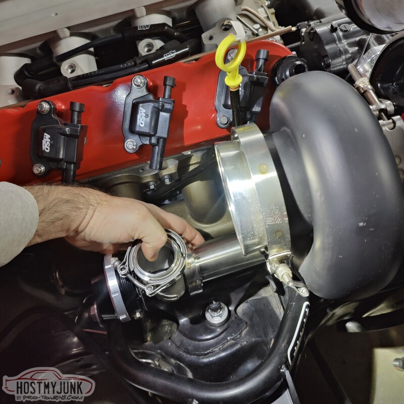
Vic also welded a Summit branded clamp to the compressor discharge. It's one of those split clamps that has o-rings and allows for some movement as everything heats up. We also sorted out the filter situation, although I will be ordering a longer filter element to get as much surface area as possible. This one is 6.5" tall, and K&N has a 10" long version that will fit perfectly in the available space.
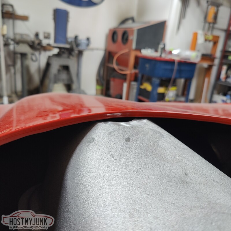
Now for the elephant in the room. The hood still doesn't close. This picture makes the situation look worse than it is, but you get the idea. The "bubble" at the top of the intake is about 1" too tall to allow the hood to close.
After considering all the options, we are going to start with the simple solution. We are going to mill down the bubble so the hood closes and see what we have left.
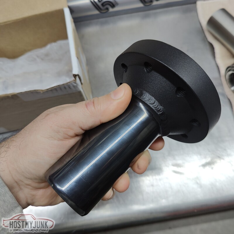
Back in 2010, I contacted The DriveShaft shop to solve a vibration issue in the GTO. They made me a CV driveshaft that use a CV at the slip yoke and a u-joint in the rear, which solved my vibration issues. Since then, many other A-body owners have done the same thing with the same, great results. When I built the Cougar, I wanted to go a step further and do a double CV shaft. That too had amazing results. If you look at any modern, RWD muscle car, that is exactly what you will see.
This version of the GTO will also get a dual CV driveshaft and this is the second part of that puzzle (the first being the CV pinion yoke). This slip yoke will use their new, non-plunging CV. This is the same CV they use on their high HP Nissan GTR and other driveshafts.
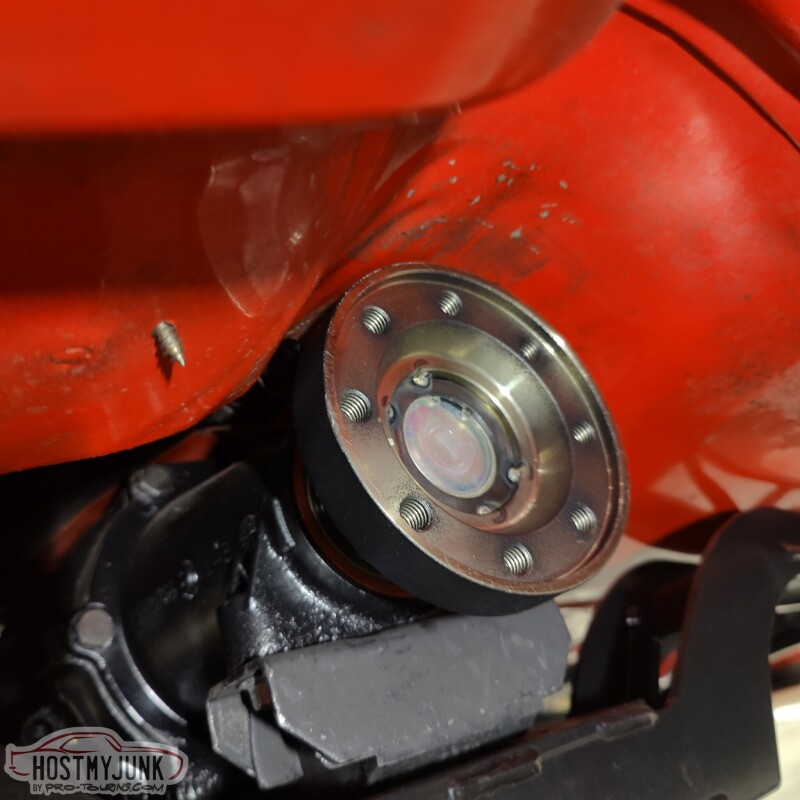
It's a tight fit, but there is a minimum of 3/8" all the way around the yoke. (what the hell was I thinking, twenty years ago, with the sheet metal screw?!)
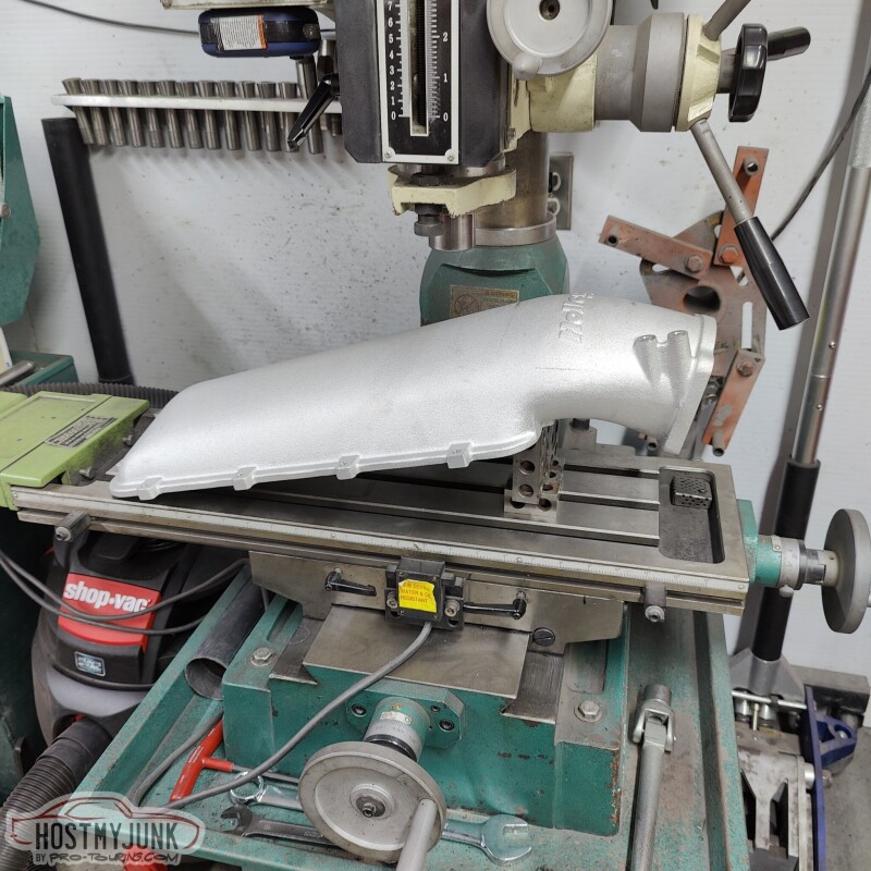
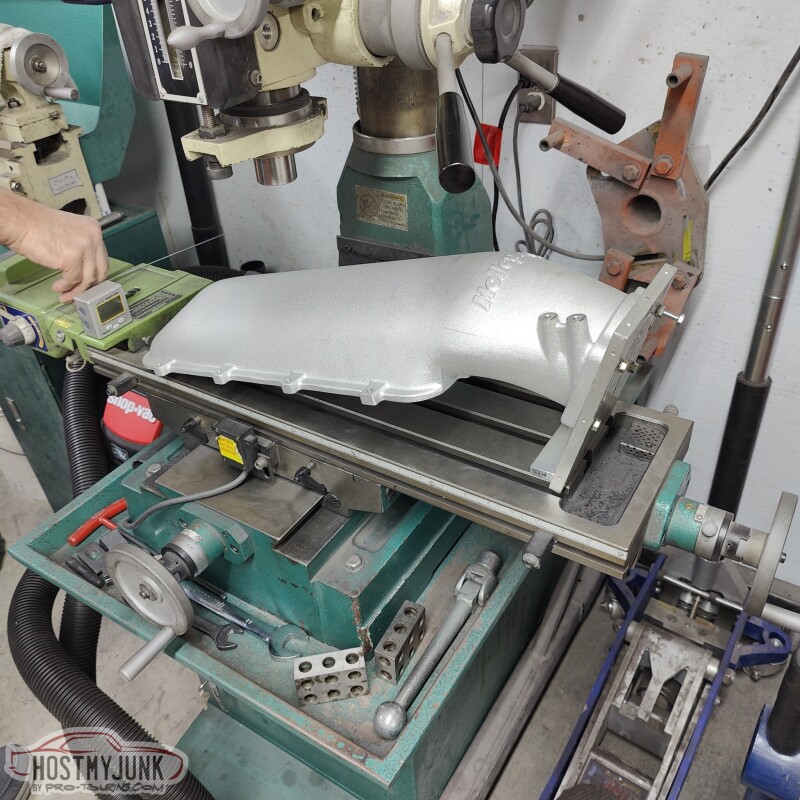
Vic made a fixture to hold the intake lid on the mill. We positioned it at the approximate angle of the hood.
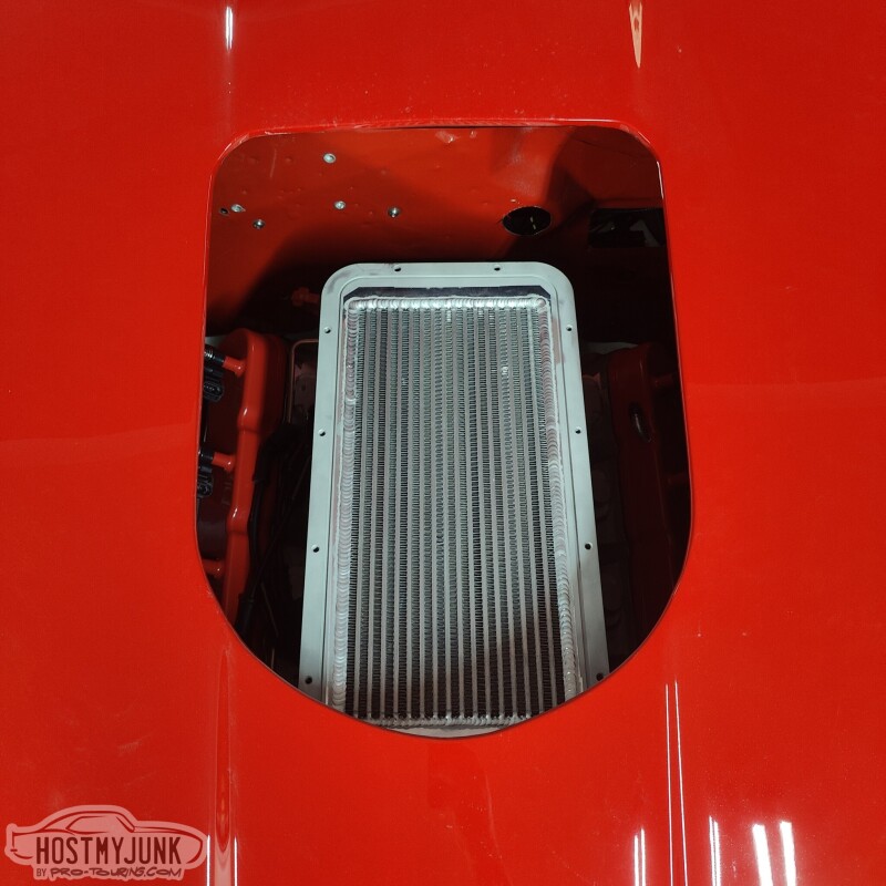
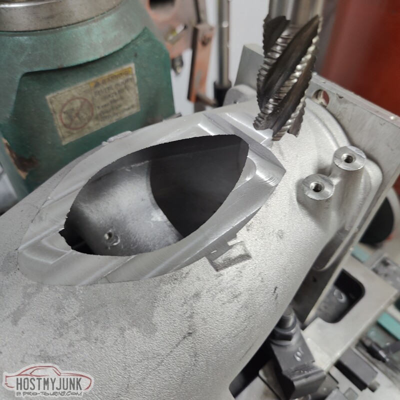
We took about 3/4" off the peak of the bubble and this was the hole that was made.
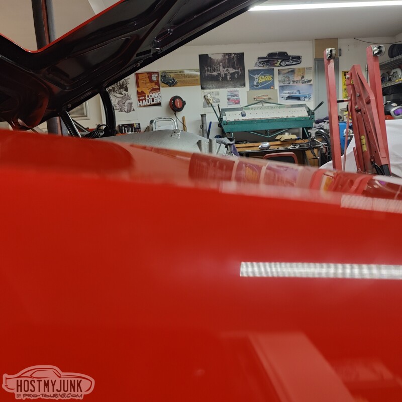
And the hood closed. As you can see, it is really tight, but nothing is touching. We are going to take a little bit more off to make room for the eventual plate that will get welded to cover the hole.
This is the current thinking on wastegate placement. My only reservation is that it be under the downpipe and will be a pain to get to if I have to do something with the wastegate.
The upside is that it will have excellent, priority flow and will merge back into the downpipe.
If anyone has thoughts on the wastegate placement, please chime in.
And the hood closed. As you can see, it is really tight, but nothing is touching. We are going to take a little bit more off to make room for the eventual plate that will get welded to cover the hole.
Andrew - I am SURE you have thought about this, but are you concerned with engine vibration that may cause the intake to hit the hood? Regardless of how tight the motor mounts are, it moves a bit. I'd hate for you to go through all this work and then have it rattle against the hood.
Andrew - I am SURE you have thought about this, but are you concerned with engine vibration that may cause the intake to hit the hood? Regardless of how tight the motor mounts are, it moves a bit. I'd hate for you to go through all this work and then have it rattle against the hood.
-Jim
Jim,
That's certainly a concern. The driver's side mount is poly and the passenger side mount is solid aluminum. We did that because of the proximity of the exhaust manifold to the engine mount on the passenger side.
I'm really not sure how much it will move, but it will move some. I think at this point the plan is to leave about 1/4-3/8 inch of clearance. Is that enough? I'm not sure.
Andrew
I vaguely remember something in the thread about one poly and one solid mount. Is 1/4 - 3/8 enough? Only one way to find out.
This has been an awesome build to follow and we appreciate your patronage throughout it! You have detailed updates good/bad with quality images to showcase the progress of the build. We like that you're using one of our HD Dual Seal Clamps for the compressor discharge. These are robust clamp assemblies that allow for movement/misalignment. Using them on the compressor discharge is a great way to showcase how they can be used. We'll be sure to continue following along on this impeccable build

 11-30-2022, 09:30 PM