
1970 GTO Version 3.0
 09-27-2022, 01:16 PM
#541


Being at LS Fest last weekend got me motivated again to work on the GTO. The fact that it is a lot cooler is helping as well. I needed to get everything ready to drop the engine and trans in the car, because until that happens, anything to do with mocking up the hot side of the turbo is just guessing.
As some of you might recall, I only replaced the passenger side of the front suspension, which also meant that I did not replace the driver's side engine frame stand.
Yesterday I decided to tackle that project. First order of business was to assemble this awesome rolling chair from Vyper. They are super well made, right here in the US. Highly recommended.
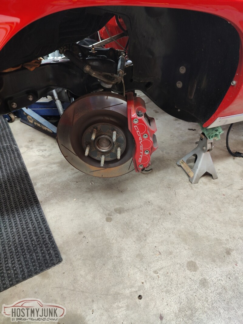
Here is what was going on after I took the wheel off.
I removed all of the front suspension...
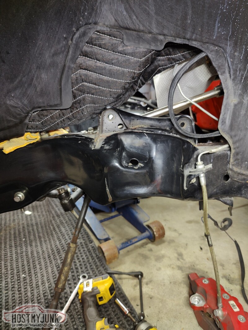
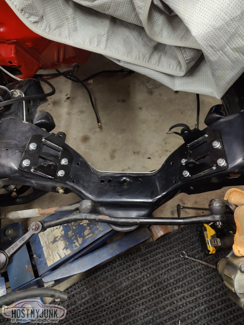
Then I was able to install the Holley LS swap frame stands.
Then back together it went with the new Ridetech suspension and coilovers.
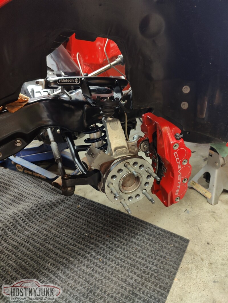
I didn't have time to get the rotor back on, but at least everything is cleaned up and the car rolls again.
Andrew
As some of you might recall, I only replaced the passenger side of the front suspension, which also meant that I did not replace the driver's side engine frame stand.
Yesterday I decided to tackle that project. First order of business was to assemble this awesome rolling chair from Vyper. They are super well made, right here in the US. Highly recommended.
Here is what was going on after I took the wheel off.
I removed all of the front suspension...
Then I was able to install the Holley LS swap frame stands.
Then back together it went with the new Ridetech suspension and coilovers.
I didn't have time to get the rotor back on, but at least everything is cleaned up and the car rolls again.
Andrew
Thanks
Ken

 10-02-2022, 03:13 PM
#543
TECH Senior Member
Thread Starter
iTrader: (7)
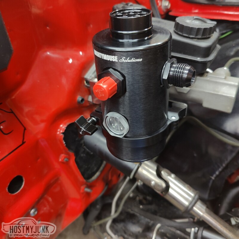
Made a little more progress today. Got the MM Solutions catch can bracket mounted to the booster bolts. The bracket needed a little TLC to clear the bottom bolts.
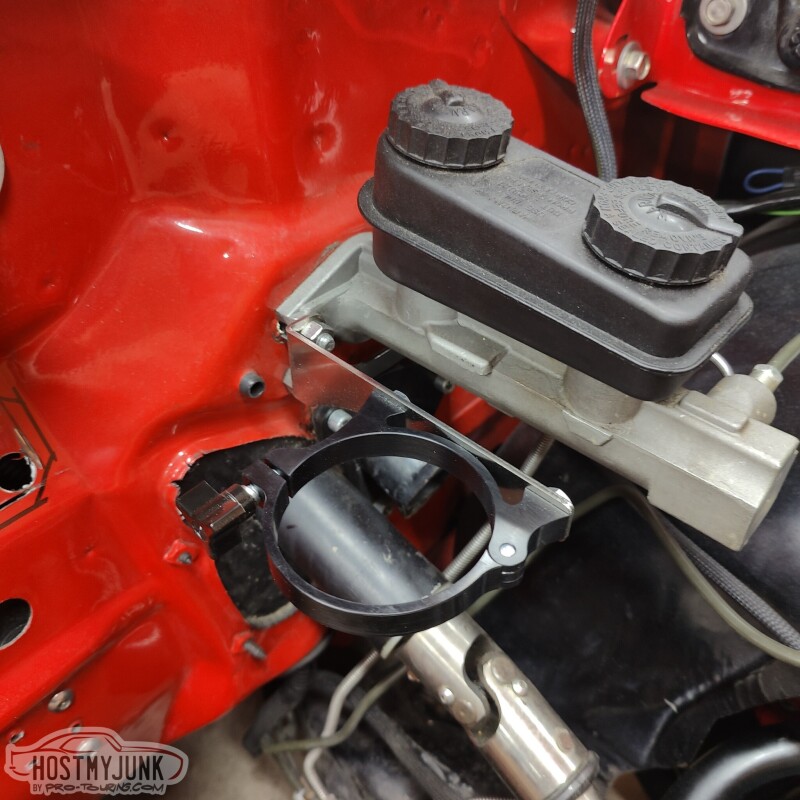
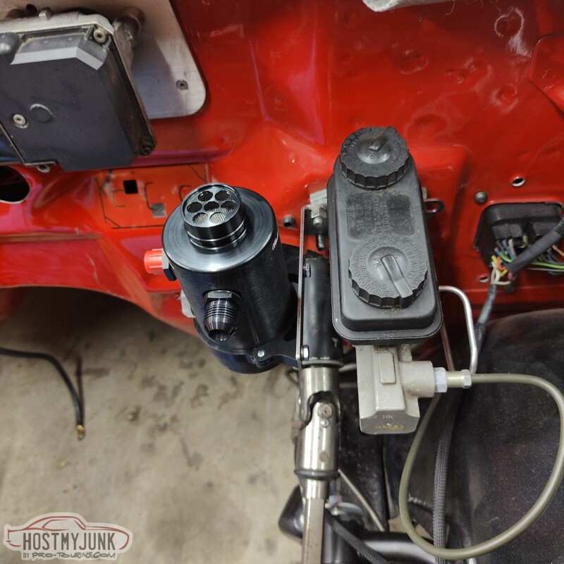
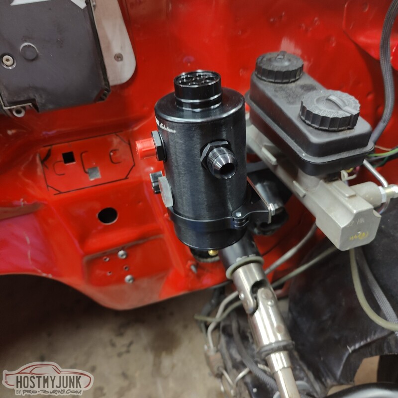
It fits nicely in this location and should not be in the way of anything, like the exhaust.
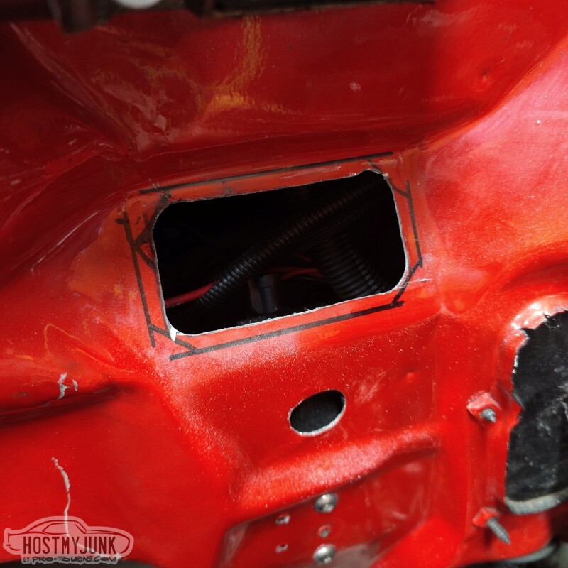
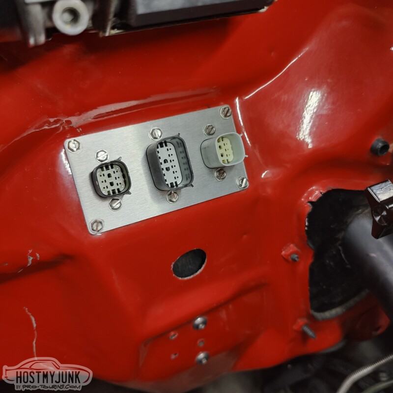
I then used a step drill to open up the corners of the hole where the little panel is going to go.
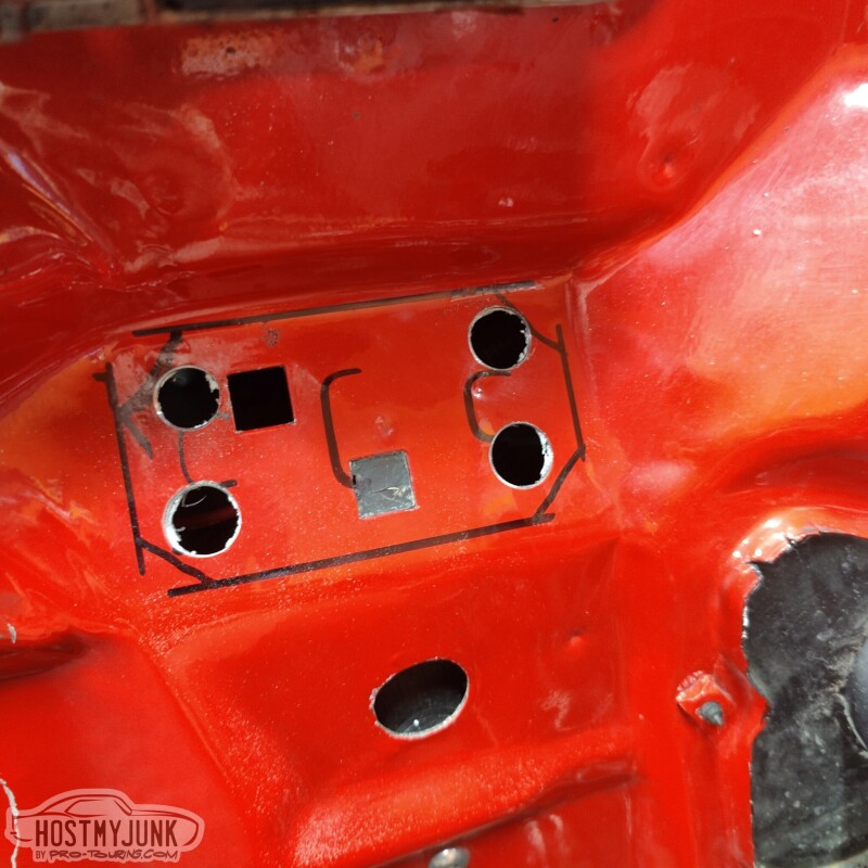
Then I used a cut off wheel and a little saw to connect the dots.
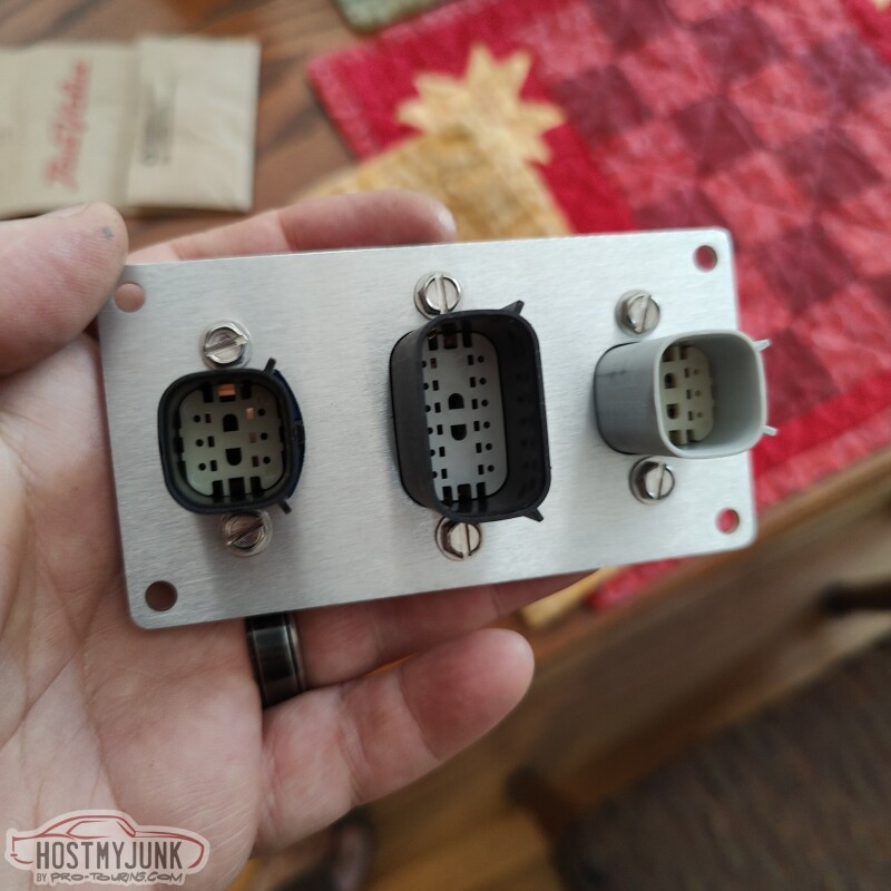
This is the panel with the Molex bulkhead connectors attached.
Andrew
It fits nicely in this location and should not be in the way of anything, like the exhaust.
I then used a step drill to open up the corners of the hole where the little panel is going to go.
Then I used a cut off wheel and a little saw to connect the dots.
This is the panel with the Molex bulkhead connectors attached.
Andrew
10-03-2022, 12:16 PM
#544
The following users liked this post:
c5golfguy (06-01-2023)
The following 3 users liked this post by ls1nova71:
10-27-2022, 11:27 AM
#548
TECH Senior Member
Thread Starter
iTrader: (7)
Yesterday was a beautiful fall day and it gave me the opportunity to get the GTO to Vic's house.
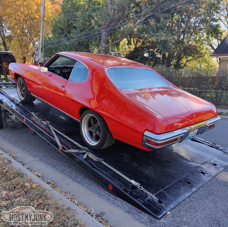
After I get back from SEMA, the plan is to start cranking on it and get the engine and transmission installed and start on the turbo fab work.
Andrew
After I get back from SEMA, the plan is to start cranking on it and get the engine and transmission installed and start on the turbo fab work.
Andrew
The following 5 users liked this post by Project GatTagO:
93Polo (10-27-2022), Jimbo1367 (10-28-2022), kwhizz (10-28-2022), Motown 454 (10-27-2022), Pro Stock John (10-27-2022)
11-20-2022, 09:14 PM
#549
TECH Senior Member
Thread Starter
iTrader: (7)
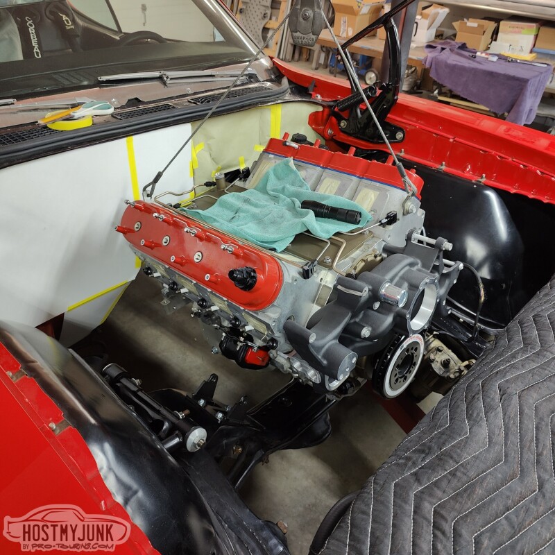
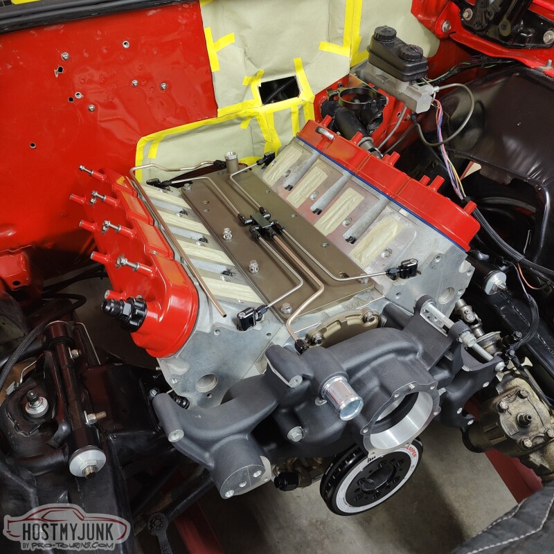
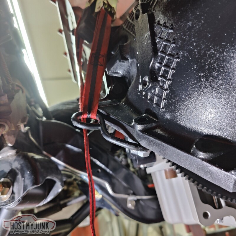
Today was a big day. I went over to Vic's house with the goal of mocking up the engine in the engine bay. I had confidence that the Holley swap components would not be an issues, but the big area of concern was the oil drain back fitting for the turbo on the side of the Holley 302-3 pan. Holley designed those drain backs in a Fox body Mustang, and when used with a GM A-body there was some concern that the fitting would hit the front crossmember.
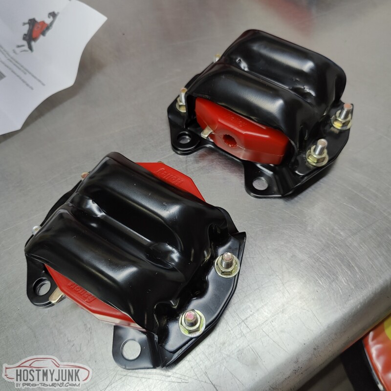
These are the Holley clamshells with the poly inserts. They are dimensionally identical to 4th gen Camaro engine mounts, except with a bolt together design and poly inserts.
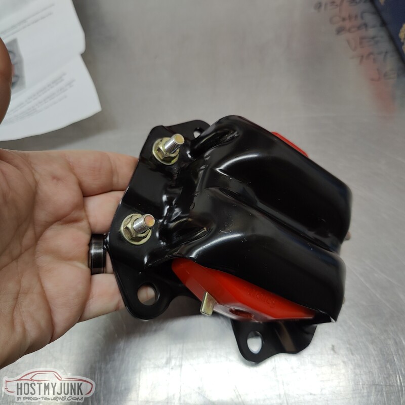
I am not sure why Holley includes such long bolts, but I decided to keep them and the included lock nuts. They will not be visible at all once everything is bolted to the engine.
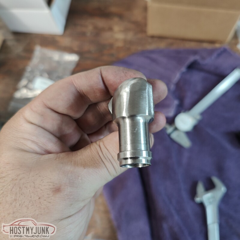
After mocking up the engine the first time, it was clear that the oil drain fitting that I got was not going to work. At least not without some modifications.
I can't believe I have gone this long without having a lathe and a mill. Both were used to modify the Earl's fitting in order to make it fit.
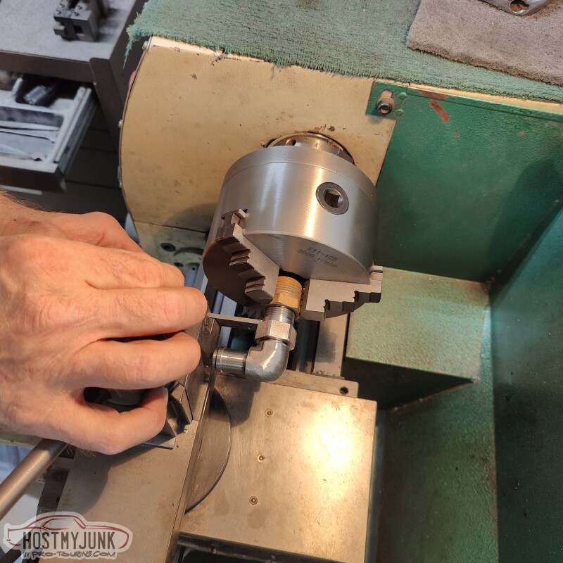
The lathe was used to back-cut the area between the end of the threads and the hex area. This was done so that the fitting can be installed deeper into the boss on the side of the pan. The mill was used to trim the end of the threads, because with the fitting screwed in deeper, it would hit the oil pick-up tube.
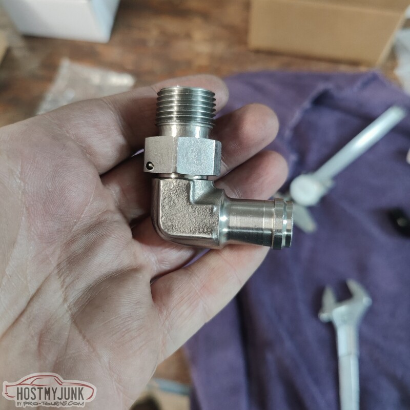
The outside of the fitting was also smoothed and contoured on the belt sander. It is a rather bulky fitting and there was plenty of material to remove in order for the fitting to match the contour of the front cross member. The pan was also removed in order to tap the 1/2" NPT threads a little deeper.
It took a total of six rounds to get it to the point where the engine mounts dropped into the frame stands and the mounting bolts to slide in.
The fitting has about 1/8" clearance against the crossmember, and it is able to pivot freely.
With some luck, the transmission and the converter will go in on Wednesday and then Vic can start the fabrication for the turbo hotside.
Andrew
These are the Holley clamshells with the poly inserts. They are dimensionally identical to 4th gen Camaro engine mounts, except with a bolt together design and poly inserts.
I am not sure why Holley includes such long bolts, but I decided to keep them and the included lock nuts. They will not be visible at all once everything is bolted to the engine.
After mocking up the engine the first time, it was clear that the oil drain fitting that I got was not going to work. At least not without some modifications.
I can't believe I have gone this long without having a lathe and a mill. Both were used to modify the Earl's fitting in order to make it fit.
The lathe was used to back-cut the area between the end of the threads and the hex area. This was done so that the fitting can be installed deeper into the boss on the side of the pan. The mill was used to trim the end of the threads, because with the fitting screwed in deeper, it would hit the oil pick-up tube.
The outside of the fitting was also smoothed and contoured on the belt sander. It is a rather bulky fitting and there was plenty of material to remove in order for the fitting to match the contour of the front cross member. The pan was also removed in order to tap the 1/2" NPT threads a little deeper.
It took a total of six rounds to get it to the point where the engine mounts dropped into the frame stands and the mounting bolts to slide in.
The fitting has about 1/8" clearance against the crossmember, and it is able to pivot freely.
With some luck, the transmission and the converter will go in on Wednesday and then Vic can start the fabrication for the turbo hotside.
Andrew
The following users liked this post:
kwhizz (11-22-2022)
11-23-2022, 09:02 PM
#550
TECH Senior Member
Thread Starter
iTrader: (7)
Today was another big day. I hauled all of the parts that were needed to install the transmission to Vic's house. We started around 10am and made excellent progress.
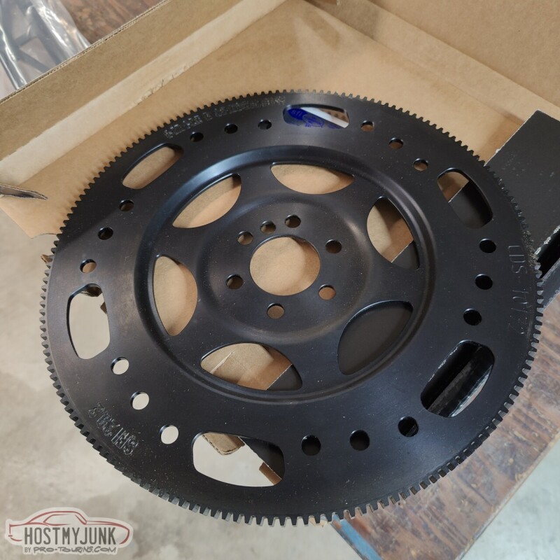
This is a billet steel SFI approved flex plate from Circle D. It looks amazing and has 6 converter bolts to match the Circle D billet triple disk converter.
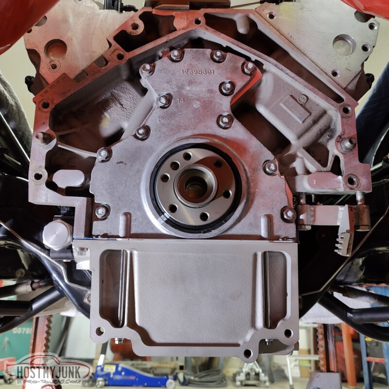
It is nice working with a clean block and a new crank. Just to make sure everything was good, I hand threaded the ARP flex plate bolts into the crank before doing anything else.
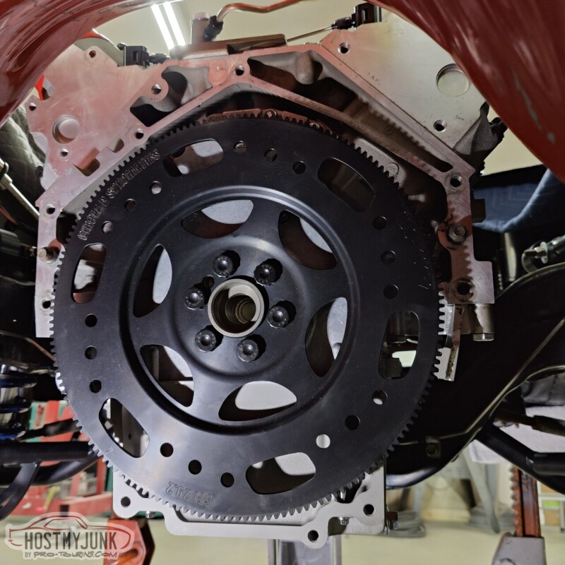
The flex plate went on without any drama and was torqued to 75lb/ft using blue Loctite. The flex plate locking tool came in handy for this task to keep the crank from rotating.
After installing the converter into the transmission (not sure why I didn't get a picture), it was time to wrestle this beast of a transmission under the car. We had some jack stands under the rear axle and jack stands under the front frame horns to get the car high enough.
It was easy enough to get a jack under the tailshaft housing, but getting the front of the transmission up was the big challenge. I suggested using the engine hoist and attaching a strap to two bolts in the transmission case. This worked great! We got the transmission high enough to slip a transmission jack under the pan for extra safety, then slowly working it up until the transmission slipped on to the dowel pins.
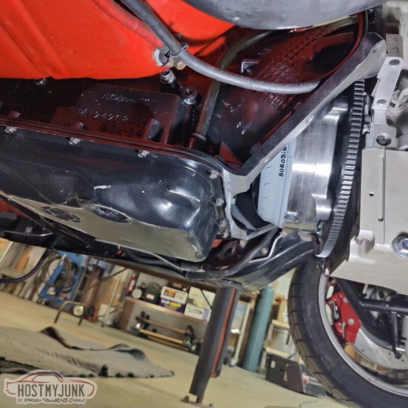
There was about a .130" gap between the converter and the flex plate, which is perfect. You can see that the pan is basically level with the frame.
We followed the instructions that came with the Holley transmission crossmember, but had a little trouble with the transmission mount that I got. I got an Energy Suspension poly mount, which is not what is specified in the instructions (should have read them before buying it). After a little searching around on Rockauto, we got a part number for a 70 GTO TH400 mount, Anchor PN 2378. The local parts store had one in stock and it ended up being about 1/2" shorter than the Energy Suspension mount. This allowed the crossmember to slip under the transmission easily, with about 3/8" of clearance.
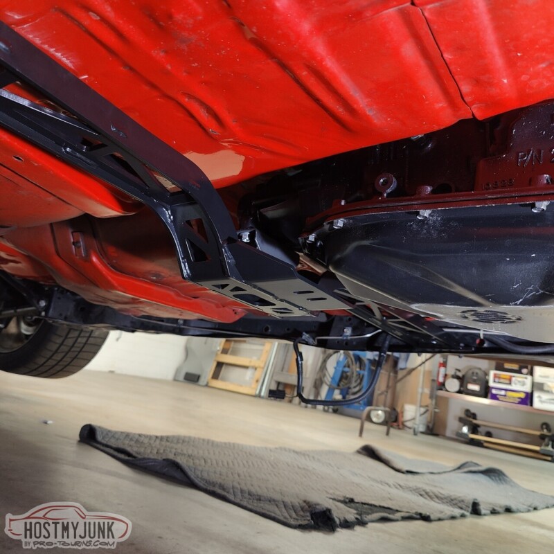
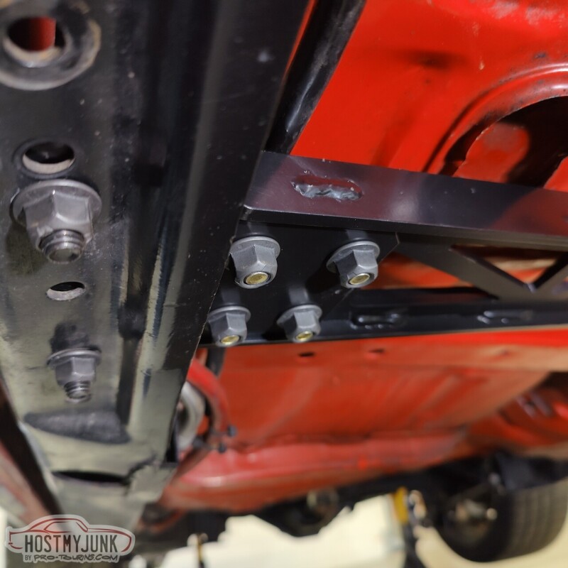
The left side of the crossmember slips over the frame rail, while the right side (shown here) has a separate pad that slips over the frame rail and the crossmember sits on top. This makes for a really solid installation.
Part of the reason I ever started this project was to redo the engine and transmission mounts and use a better fitting oil pan. I can't say enough about how well the Holley swap components are engineered to work together and how well everything fit together. In this day and age, it is hard to find parts that don't need some sort of modification to work as intended. We didn't have to modify anything!
Now that the engine and transmission are in their place, the fun stuff can start...
Andrew
This is a billet steel SFI approved flex plate from Circle D. It looks amazing and has 6 converter bolts to match the Circle D billet triple disk converter.
It is nice working with a clean block and a new crank. Just to make sure everything was good, I hand threaded the ARP flex plate bolts into the crank before doing anything else.
The flex plate went on without any drama and was torqued to 75lb/ft using blue Loctite. The flex plate locking tool came in handy for this task to keep the crank from rotating.
After installing the converter into the transmission (not sure why I didn't get a picture), it was time to wrestle this beast of a transmission under the car. We had some jack stands under the rear axle and jack stands under the front frame horns to get the car high enough.
It was easy enough to get a jack under the tailshaft housing, but getting the front of the transmission up was the big challenge. I suggested using the engine hoist and attaching a strap to two bolts in the transmission case. This worked great! We got the transmission high enough to slip a transmission jack under the pan for extra safety, then slowly working it up until the transmission slipped on to the dowel pins.
There was about a .130" gap between the converter and the flex plate, which is perfect. You can see that the pan is basically level with the frame.
We followed the instructions that came with the Holley transmission crossmember, but had a little trouble with the transmission mount that I got. I got an Energy Suspension poly mount, which is not what is specified in the instructions (should have read them before buying it). After a little searching around on Rockauto, we got a part number for a 70 GTO TH400 mount, Anchor PN 2378. The local parts store had one in stock and it ended up being about 1/2" shorter than the Energy Suspension mount. This allowed the crossmember to slip under the transmission easily, with about 3/8" of clearance.
The left side of the crossmember slips over the frame rail, while the right side (shown here) has a separate pad that slips over the frame rail and the crossmember sits on top. This makes for a really solid installation.
Part of the reason I ever started this project was to redo the engine and transmission mounts and use a better fitting oil pan. I can't say enough about how well the Holley swap components are engineered to work together and how well everything fit together. In this day and age, it is hard to find parts that don't need some sort of modification to work as intended. We didn't have to modify anything!
Now that the engine and transmission are in their place, the fun stuff can start...
Andrew
The following 4 users liked this post by Project GatTagO:
11-25-2022, 10:35 PM
#551
TECH Senior Member
Thread Starter
iTrader: (7)
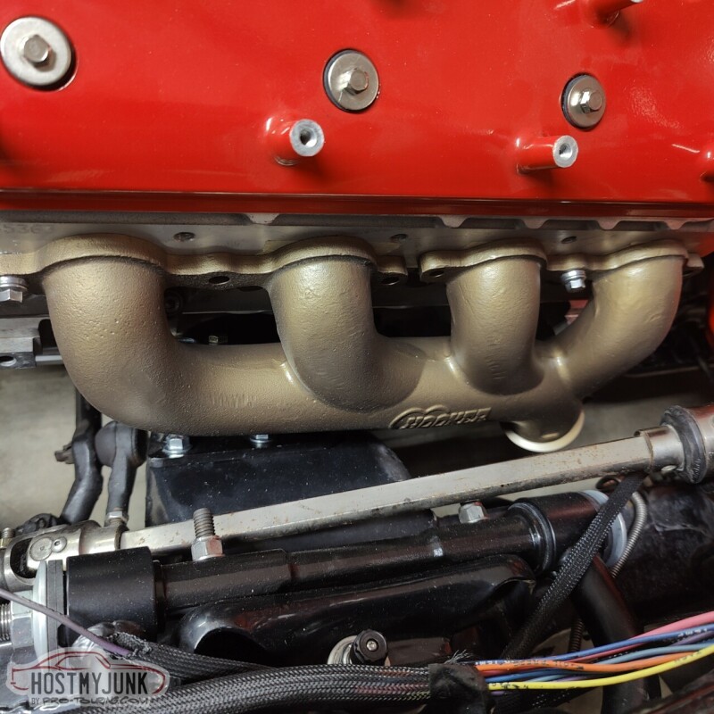
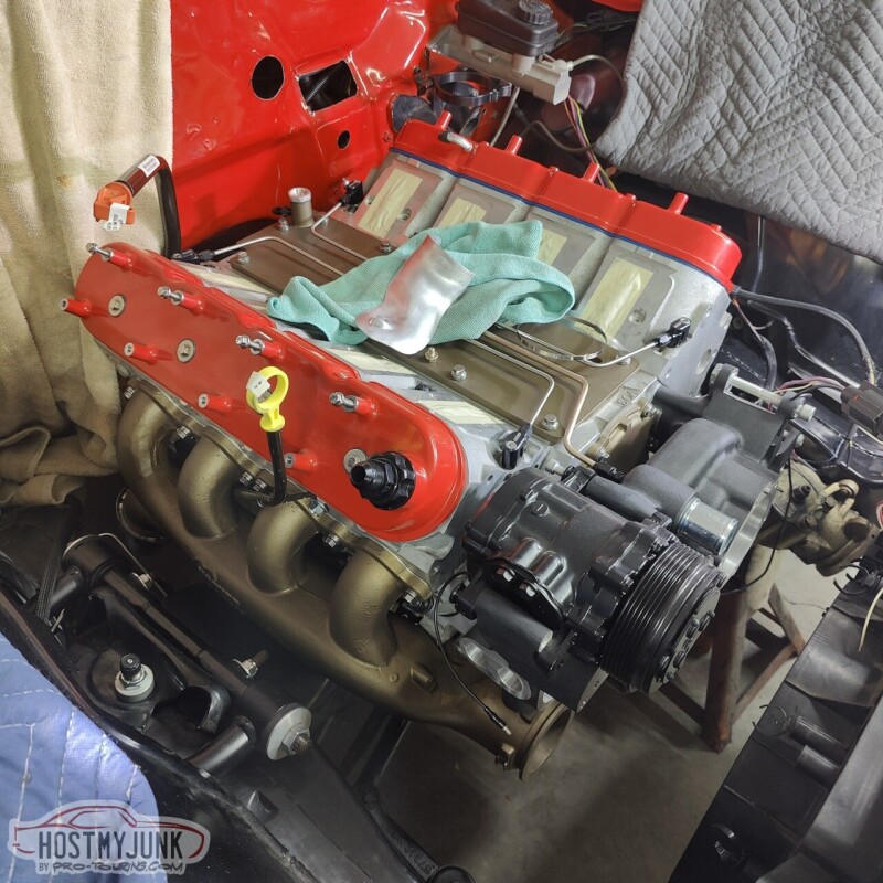
Today started out well. The driver's side manifold installed with zero issues and fits perfectly.
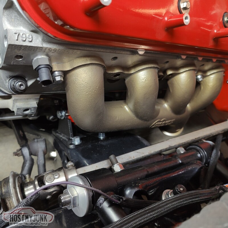
The same could not be said for the passenger side. I can't believe that I never mocked up that side with the engine mounts when the engine was on the stand...
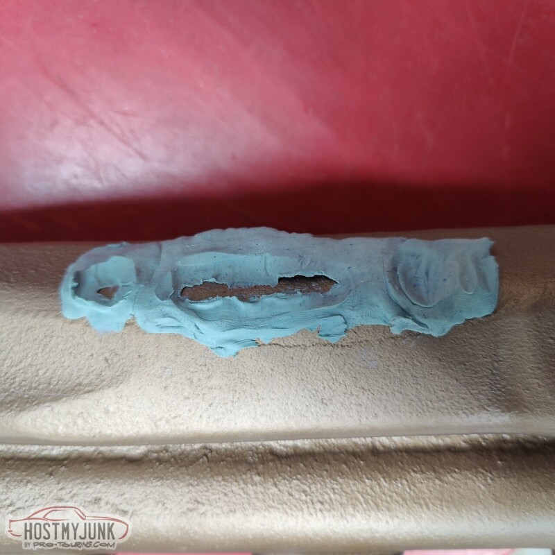
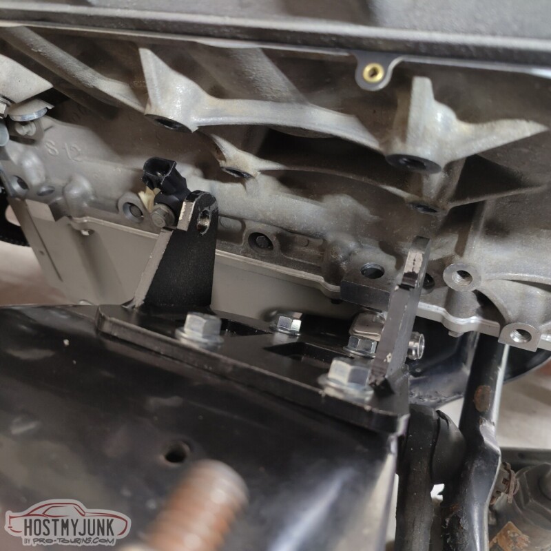
When I went to install it on the engine, it was obvious that that manifold was hitting something and it was not sitting flush with the head. We used some clay on the manifold and here you can see where it was making contact with the engine mount.
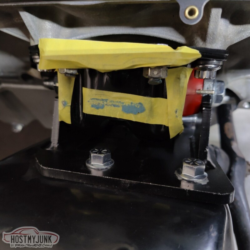
We were pretty confident that the engine mount clam shells were assembled correctly and the poly inserts were oriented properly. Otherwise the engine wouldn't have fit into the frame stands as well as it did.
Here you can see the contact spot on the manifold.
We jacked up the front right corner of the engine and removed the engine mount.
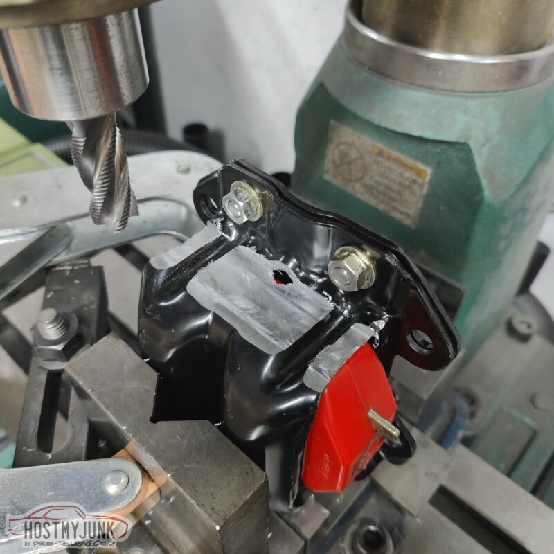
I really didn't care why it was happening, we had to fix it and keep moving forward. Vic chucked up the engine mount in the mill and we took off about .080". The material is pretty thick, so we felt confident that the integrity of the mount was not compromised. Besides, the upper clam shell is really not stressed when it is installed on the passenger side.
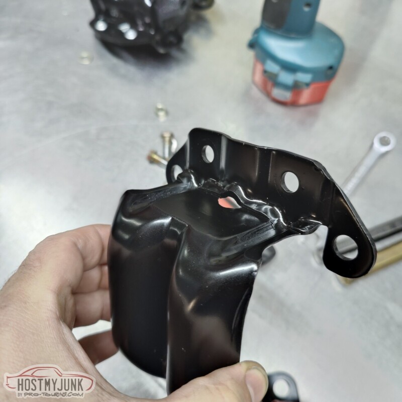
Here is the final version of the passenger side mount after a quick coat of paint. Onward!
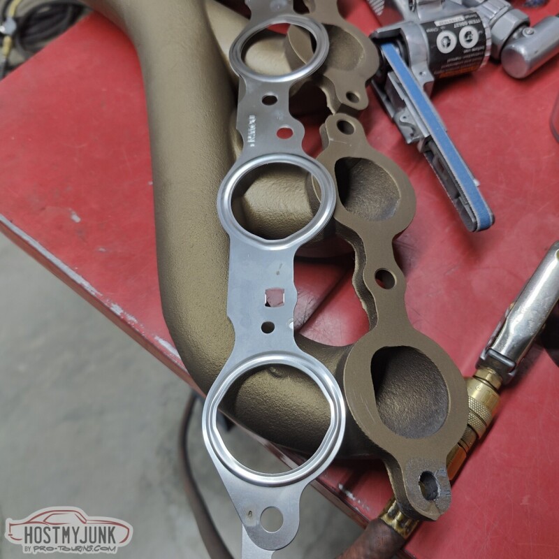
We used Mahle MLS exhaust manifold gaskets. These should seal really well and hold up to the heat.
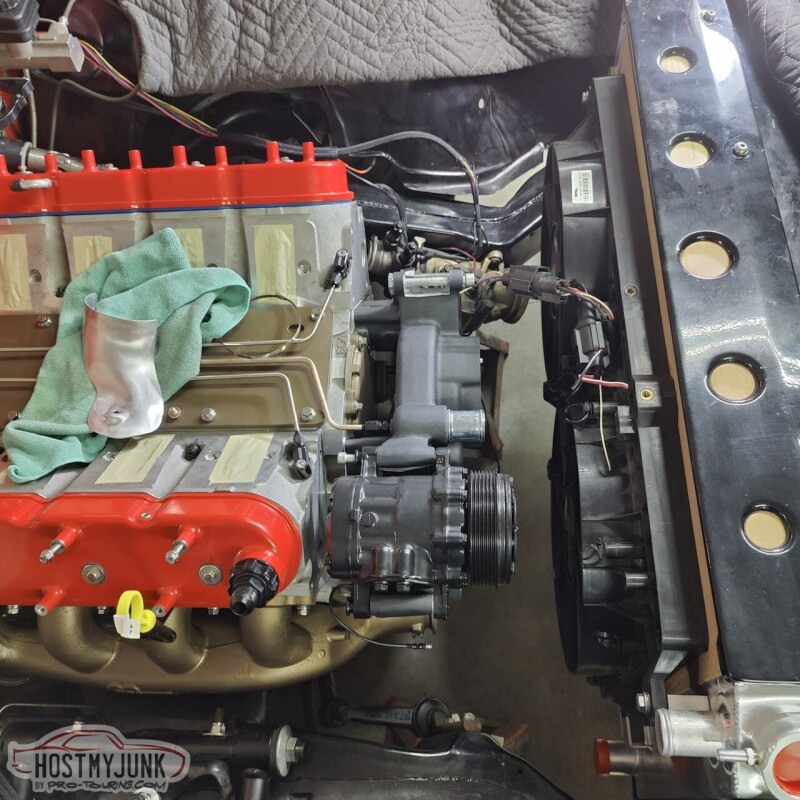
We then installed the radiator and fans to see what kind of room we had to work with.
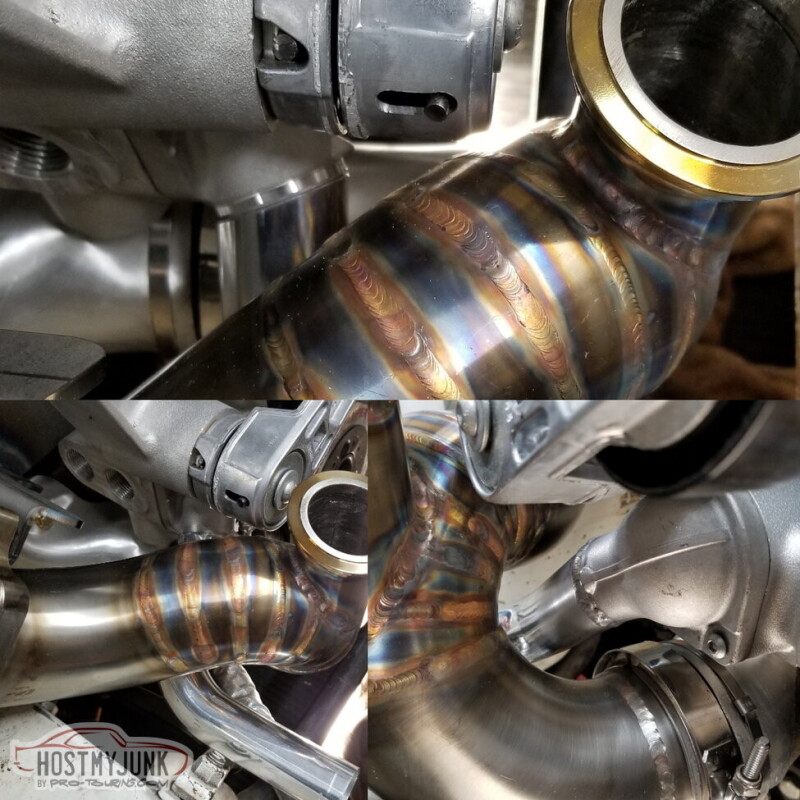
Here is the 135 degree elbow that I got from Stainless Bros as the starting point for the turbine up-pipe.

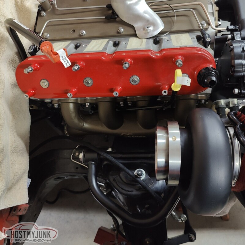
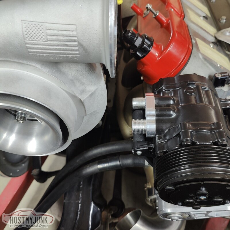
We're thinking the turbo is going to end up next to the AC compressor, oriented parallel to the engine.
Sunday we are going to do some more mocking up and maybe make a temporary mount for the turbo so that the pipes can be figured out.
Andrew
The same could not be said for the passenger side. I can't believe that I never mocked up that side with the engine mounts when the engine was on the stand...
When I went to install it on the engine, it was obvious that that manifold was hitting something and it was not sitting flush with the head. We used some clay on the manifold and here you can see where it was making contact with the engine mount.
We were pretty confident that the engine mount clam shells were assembled correctly and the poly inserts were oriented properly. Otherwise the engine wouldn't have fit into the frame stands as well as it did.
Here you can see the contact spot on the manifold.
We jacked up the front right corner of the engine and removed the engine mount.
I really didn't care why it was happening, we had to fix it and keep moving forward. Vic chucked up the engine mount in the mill and we took off about .080". The material is pretty thick, so we felt confident that the integrity of the mount was not compromised. Besides, the upper clam shell is really not stressed when it is installed on the passenger side.
Here is the final version of the passenger side mount after a quick coat of paint. Onward!
We used Mahle MLS exhaust manifold gaskets. These should seal really well and hold up to the heat.
We then installed the radiator and fans to see what kind of room we had to work with.
Here is the 135 degree elbow that I got from Stainless Bros as the starting point for the turbine up-pipe.
We're thinking the turbo is going to end up next to the AC compressor, oriented parallel to the engine.
Sunday we are going to do some more mocking up and maybe make a temporary mount for the turbo so that the pipes can be figured out.
Andrew
11-26-2022, 10:24 AM
#552

Man�� having access to a mill at home would be so nice. Almost as good as a lift.
The following 2 users liked this post by Jimbo1367:
Project GatTagO (11-26-2022), showdog75 (11-27-2022)
11-27-2022, 04:54 PM
#553
TECH Senior Member
Thread Starter
iTrader: (7)
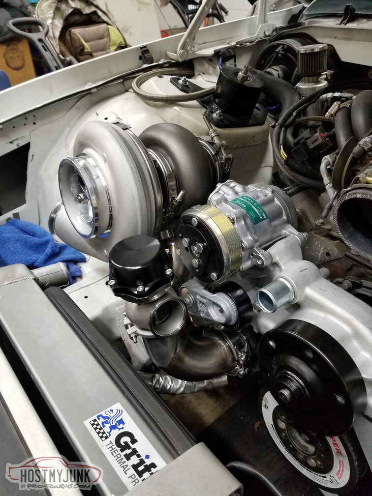
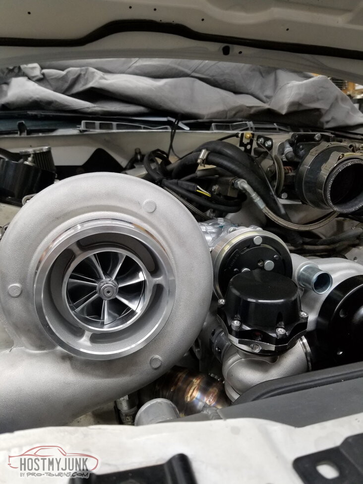
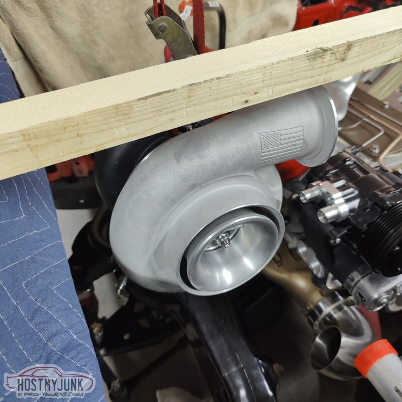
Today we attempted to mock up an approximate location for the turbo. We hung it on an engine hoist and moved it around. The following pictures show various options.
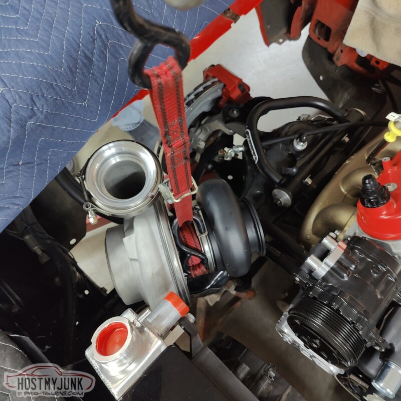
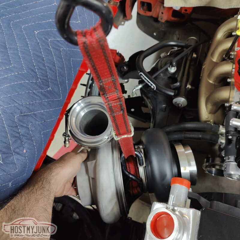
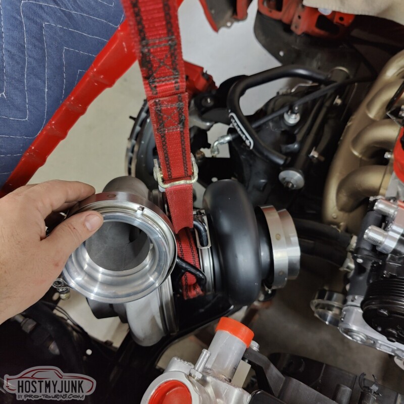
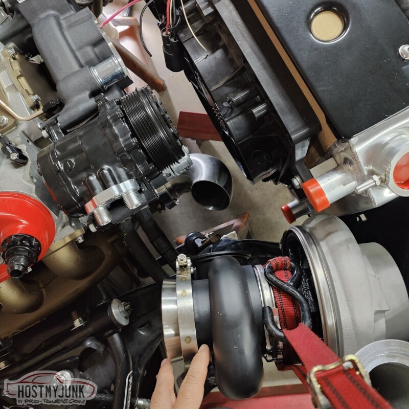
The challenge is to find a location that clears the following:
Heater hoses
AC lines
Lower radiator hose
Air filter
Bottom line, I don't think any position will work. This thing is just too big...
Andrew
The challenge is to find a location that clears the following:
Heater hoses
AC lines
Lower radiator hose
Air filter
Bottom line, I don't think any position will work. This thing is just too big...
Andrew
11-27-2022, 08:34 PM
#554
TECH Senior Member
Thread Starter
iTrader: (7)
I am not giving up. I found these picture of a 3rd gen Camaro, using the same Holley mid-mount accessory drive. Next time out I will try something similar:
Andrew
Andrew
11-28-2022, 09:53 PM
#555
TECH Senior Member
Thread Starter
iTrader: (7)
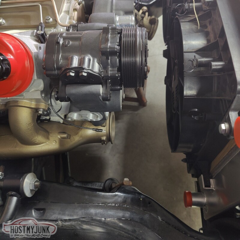
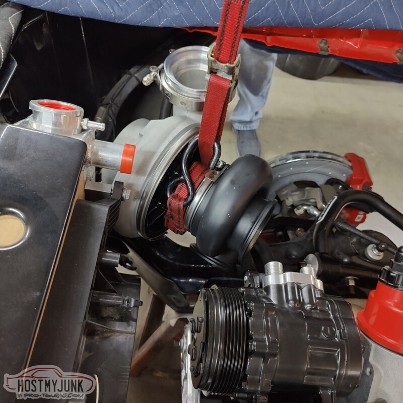
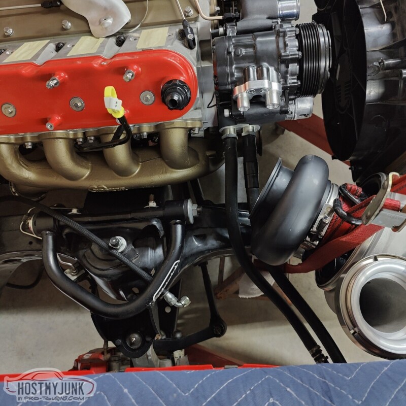
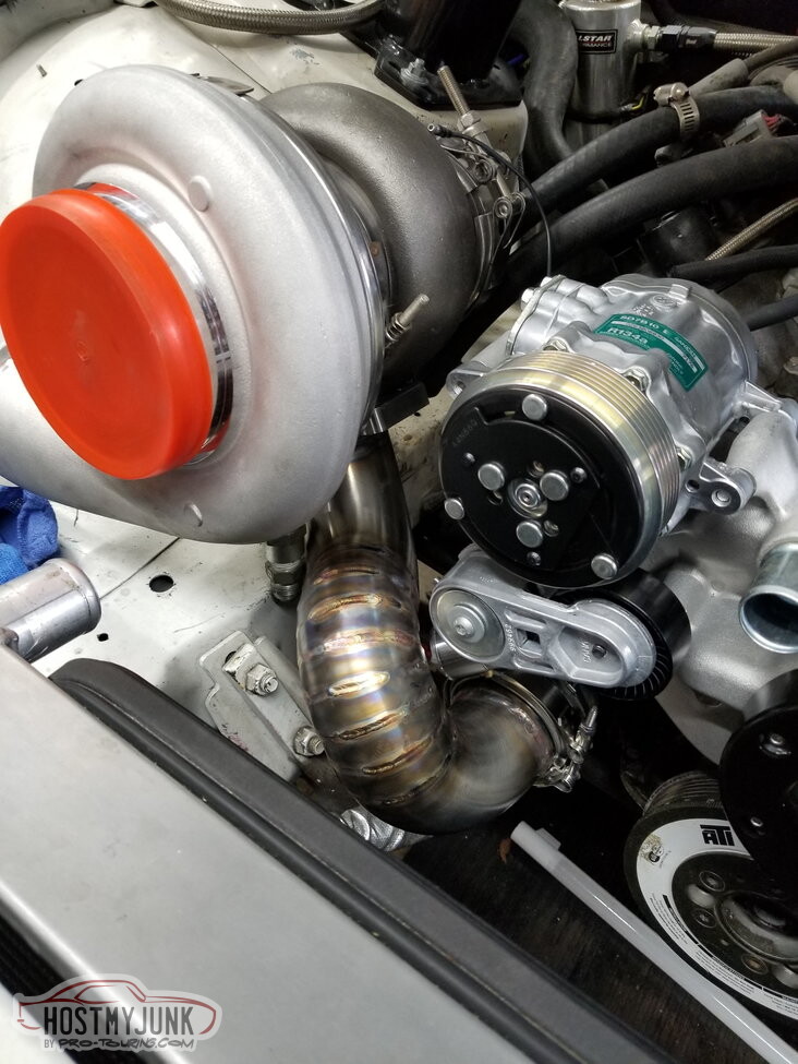
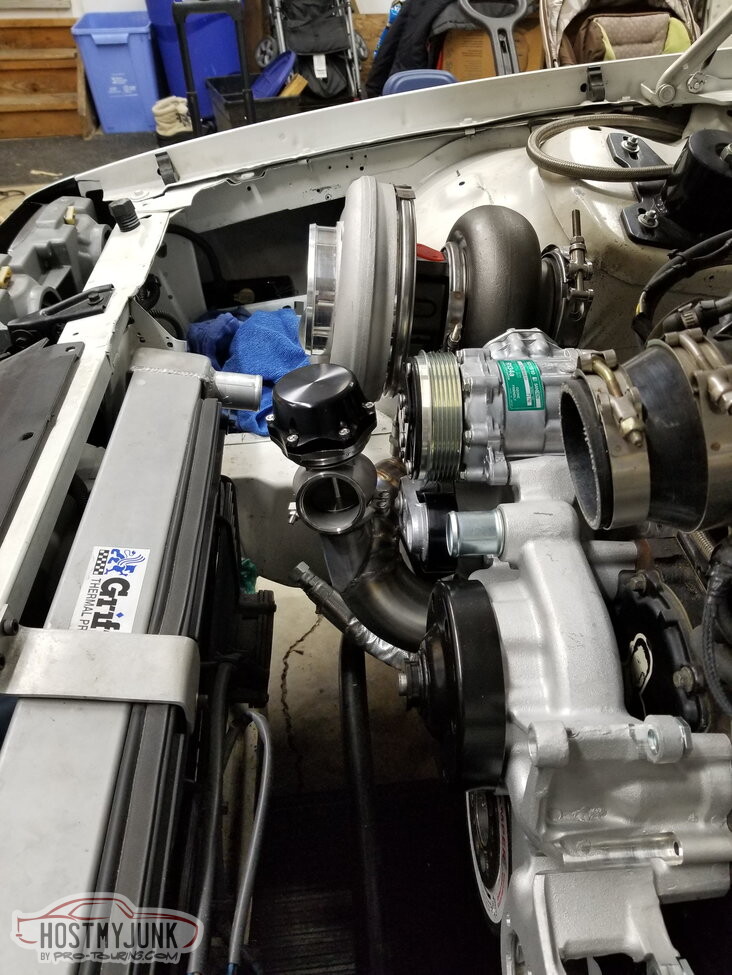
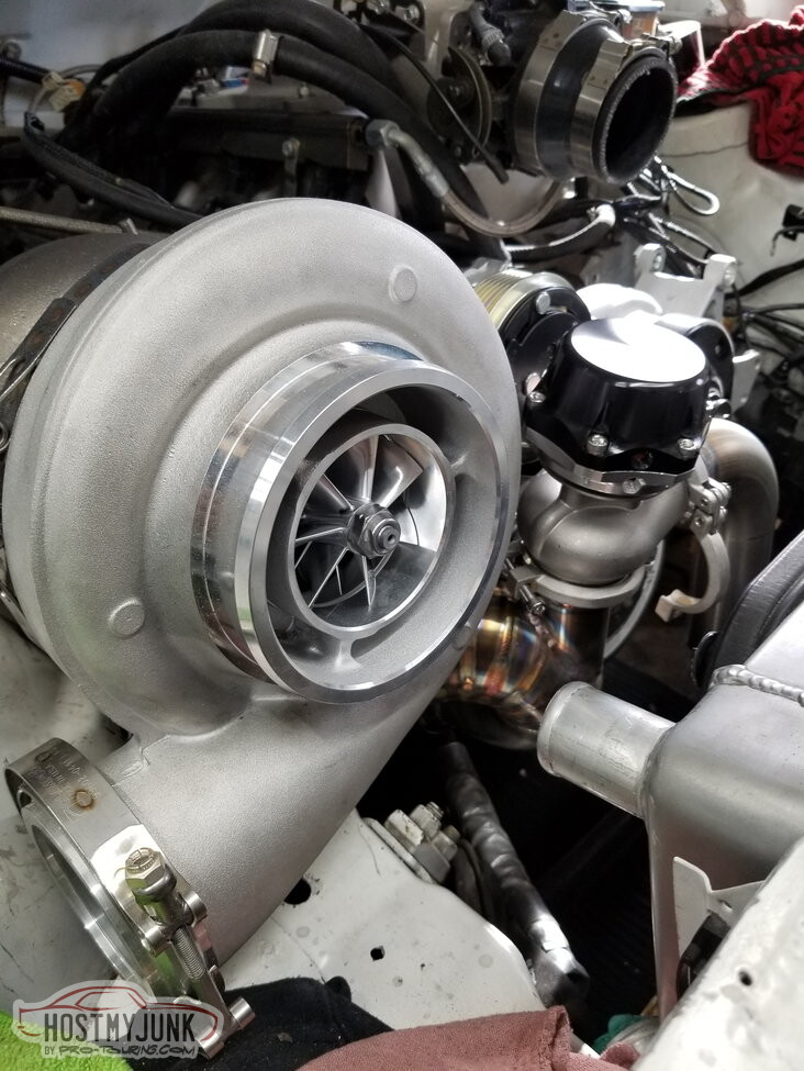
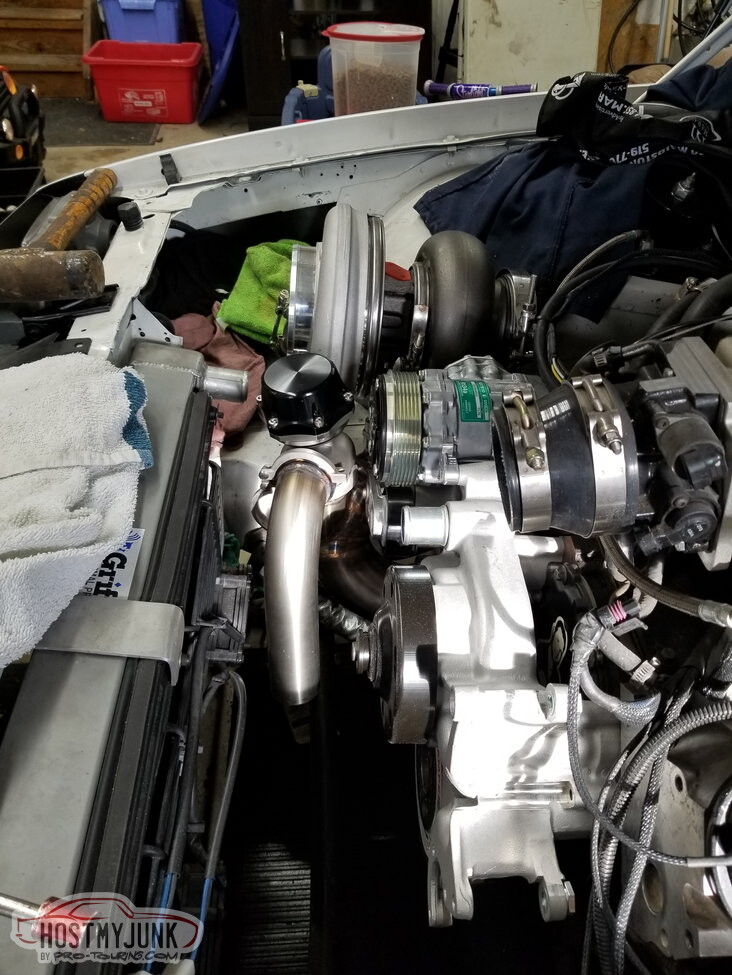
After taking a break and stepping away from it, we came up with this placement. The wood is there to simulate worst case scenario hood clearance.
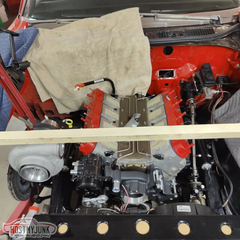
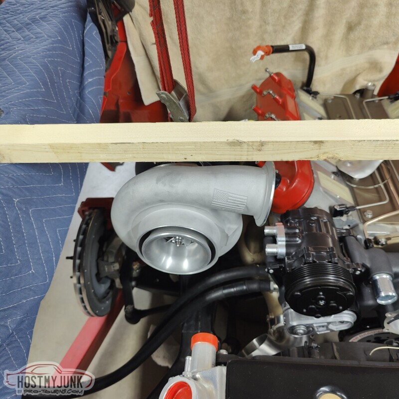
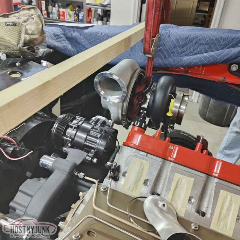
The center of the turbo is even with the Maven turbo mount. This will allow us to make a simple bracket from the head to help support the turbo.
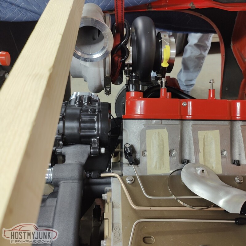
This turbo placement allows for plenty of room for all the necessary bits to clear and also gives a clear path for the turbo drain.
The inner fender will have to be modified, but that is a problem for future me...
Andrew
The center of the turbo is even with the Maven turbo mount. This will allow us to make a simple bracket from the head to help support the turbo.
This turbo placement allows for plenty of room for all the necessary bits to clear and also gives a clear path for the turbo drain.
The inner fender will have to be modified, but that is a problem for future me...
Andrew
11-29-2022, 04:52 AM
#556
Looks great. Have you run any trans lines yet? I�m curious to see what you end up using.
thanks,
jimbo
thanks,
jimbo
11-29-2022, 10:21 AM
#559
TECH Senior Member
Thread Starter
iTrader: (7)
Andrew
11-29-2022, 11:14 AM
#560
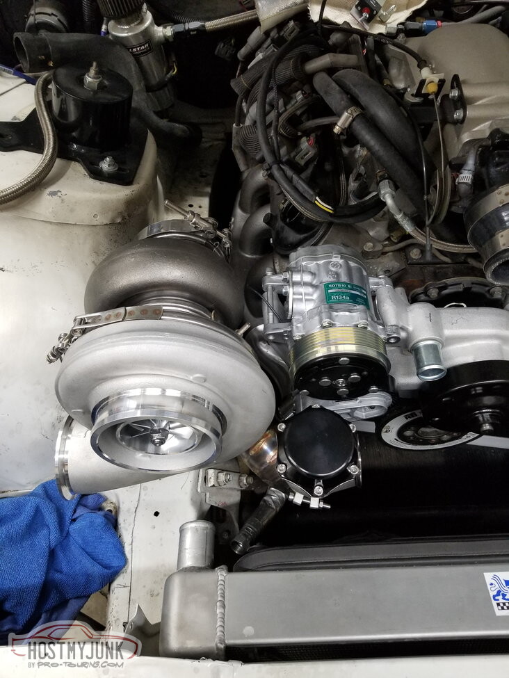
If you look closely at the last picture, you can see a Maven turbo mount under the bearing housing. You can also see that the turbo mount is aligned with the front of the head. There will be a bracket from the head to the turbo mount for added support. In fact, this needs to be built first before the pipes connect the dots.
Andrew
Andrew

The following users liked this post:
Project GatTagO (11-30-2022)