


1970 GTO Version 3.0
Thread Starter
Joined: Mar 2003
Posts: 10,617
Likes: 1,883
From: Little Austin
Before the next update, I want to send a shout out to a great vendor. It is not often that a company surpasses my expectations, but Stainless Bros definitely has.
This is how they packaged one half of the 4" v-band clams that I received from them.

Each v-band was in it's own box and the clamp itself was in its own sealed bag.
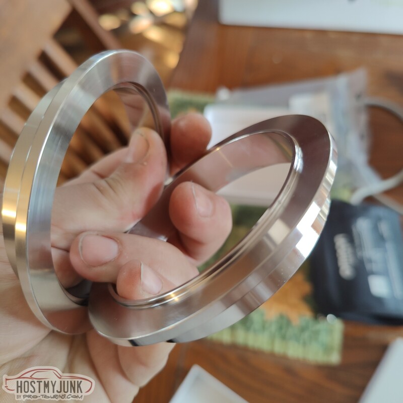
The v-bands themselves are like jewelry. Each half indexes into the other, which is a great feature that makes it easier to align the pipes.
I was also able to make it out to my local Napa store and picked up a roll of 5/16" butyl tape. I used it so seal the back of the close-out panel that I made the other day.
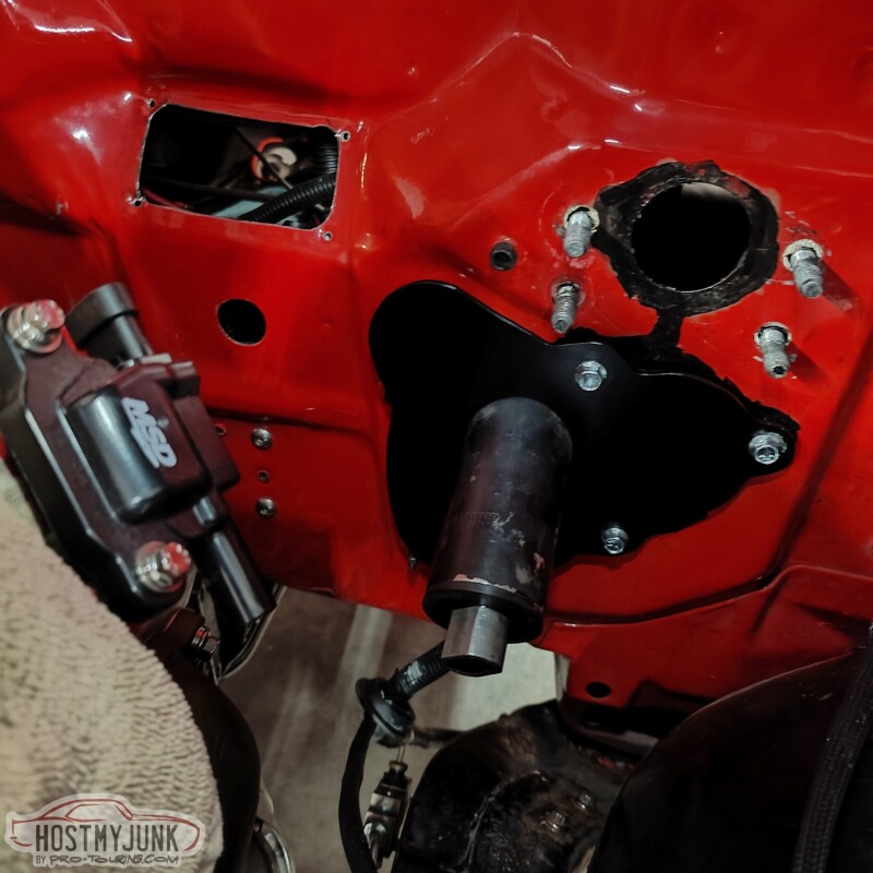
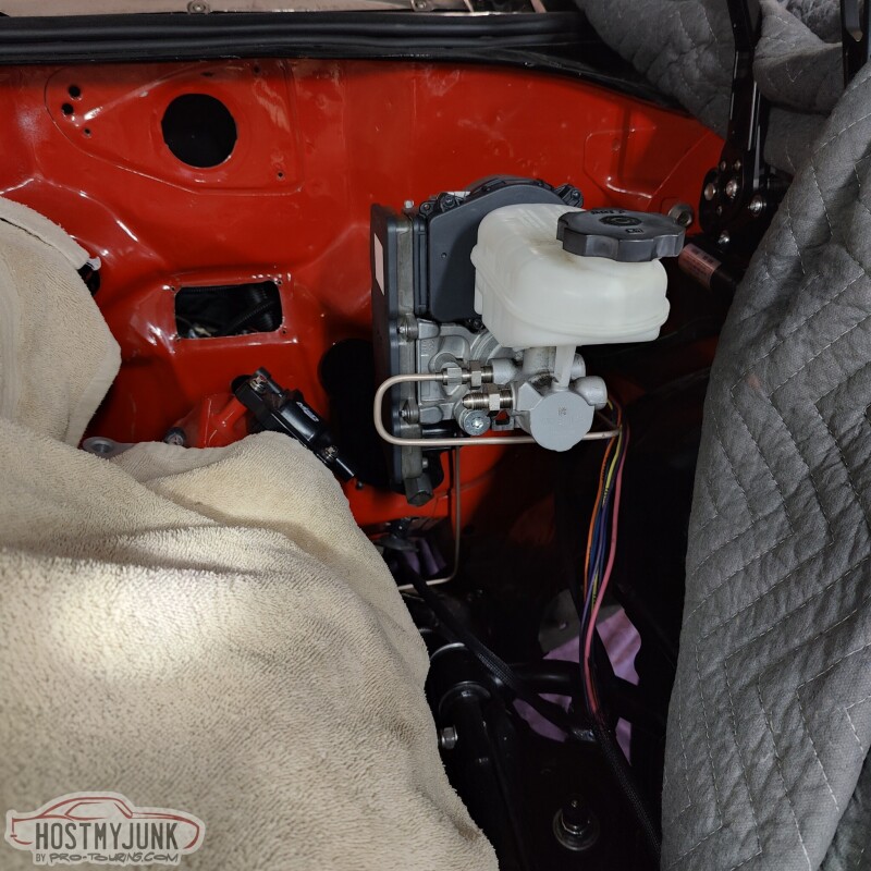
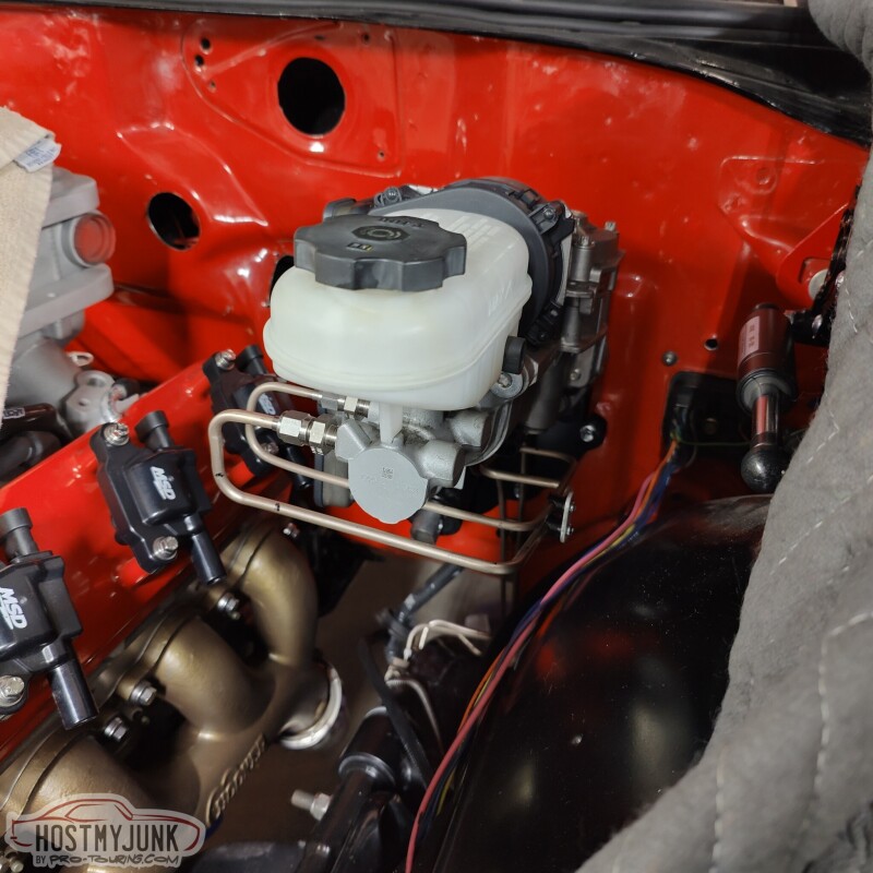
I was also able to use the boot that came from DSE. This is a boot they use with their low angle vacuum assisted booster.
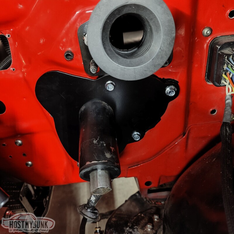
Once the iBooster is installed the plate isn't really visible.
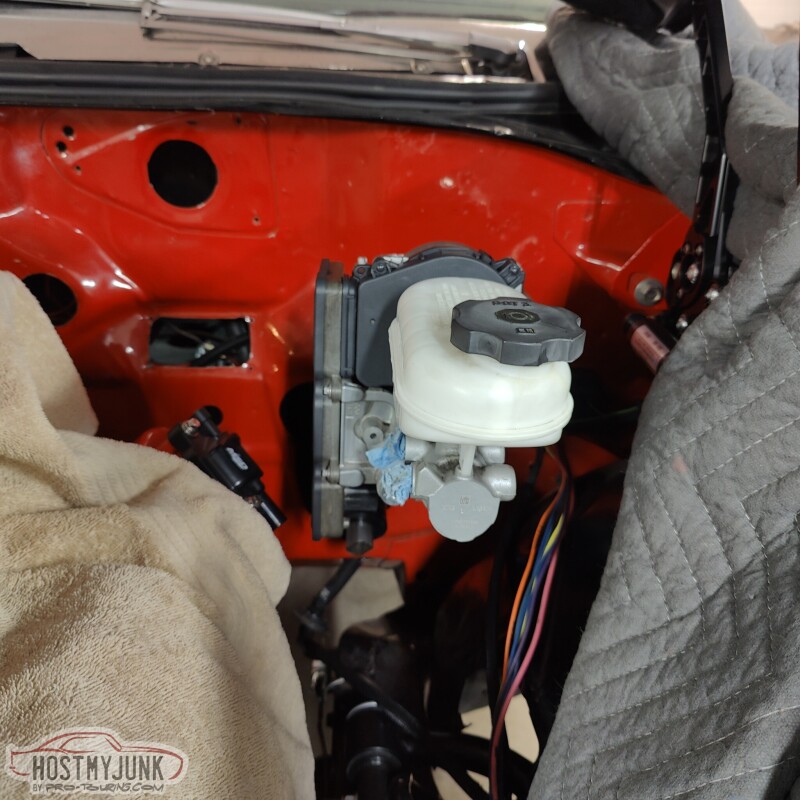
I also started on the new brake lines. I am using 3/16" NiCopp for the front brakes and 1/4" NiCopp for the rear brakes. The 12mm flare to AN adapters are from Earl's. I am not really happy with how far they stick out, but I am not sure what there is to do about it.
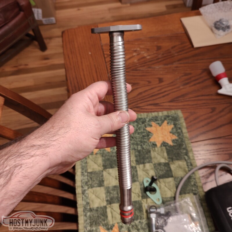
I also got this Cummins turbo drain as a starting point for my drain. More on that in a future update.
Andrew
This is how they packaged one half of the 4" v-band clams that I received from them.
Each v-band was in it's own box and the clamp itself was in its own sealed bag.
The v-bands themselves are like jewelry. Each half indexes into the other, which is a great feature that makes it easier to align the pipes.
I was also able to make it out to my local Napa store and picked up a roll of 5/16" butyl tape. I used it so seal the back of the close-out panel that I made the other day.
I was also able to use the boot that came from DSE. This is a boot they use with their low angle vacuum assisted booster.
Once the iBooster is installed the plate isn't really visible.
I also started on the new brake lines. I am using 3/16" NiCopp for the front brakes and 1/4" NiCopp for the rear brakes. The 12mm flare to AN adapters are from Earl's. I am not really happy with how far they stick out, but I am not sure what there is to do about it.
I also got this Cummins turbo drain as a starting point for my drain. More on that in a future update.
Andrew
Thread Starter
Joined: Mar 2003
Posts: 10,617
Likes: 1,883
From: Little Austin
I spent a little time at Vic's today working on various odds and ends.
This is a clever little part from Motion Raceworks. It's an oil inlet block that bolts to the top of the oil feed hole and seals with an o-ring. It then points the oil feed line straight out the side. This will connect to the oil feed line, which at the moment terminates at the front of the passenger side head.
A few days back Vic also made this fantastic mount for the Dominator ECU. It bolts in place of the glove box and will allow me easy access to the ECU connectors. Ignore the duct tape. I will be placing an order with Vintage Air soon to clean up the under-dash ducting in anticipation of having working AC in the car.
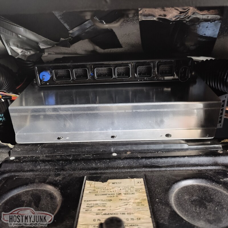
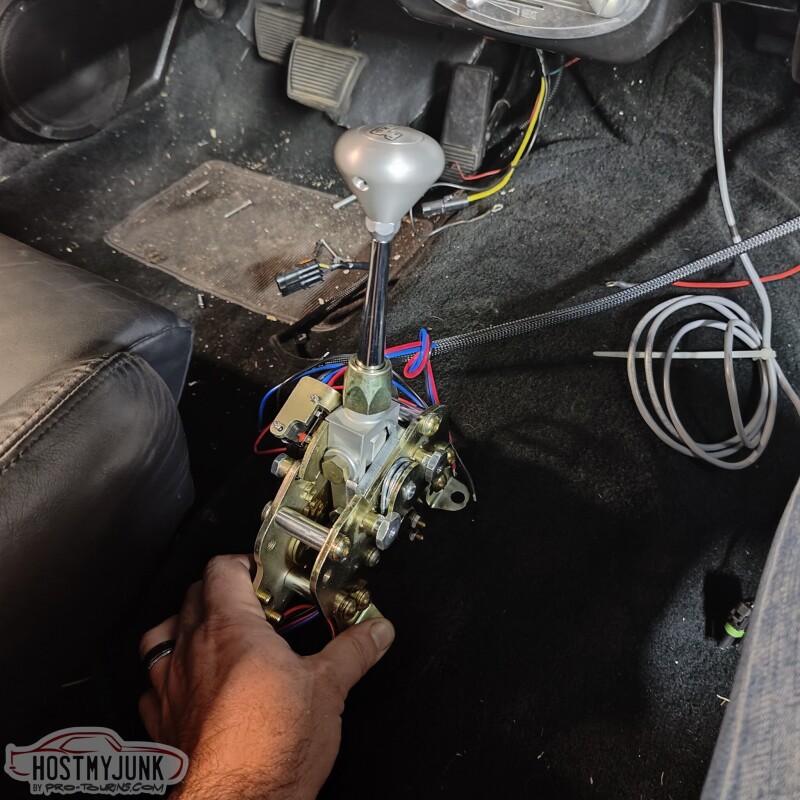
I also brought the shifter to see how it might fit inside the car. In the picture I have it sitting over the hole where my manual shifter was located. It is slightly offset to the driver's side. I am not really sure about the shifter placement yet.
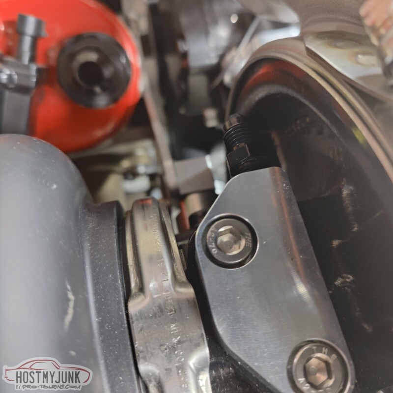
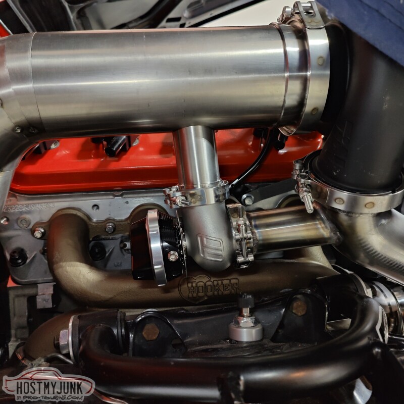
Vic worked out the final placement of the waste gate and started on the fabrication of the needed plumbing.
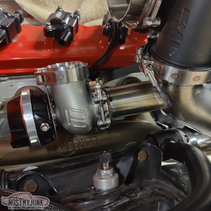
It should have good priority flow in this location and provide an easy path to route the exhaust from the waste gate back into the downpipe.
Andrew
This is a clever little part from Motion Raceworks. It's an oil inlet block that bolts to the top of the oil feed hole and seals with an o-ring. It then points the oil feed line straight out the side. This will connect to the oil feed line, which at the moment terminates at the front of the passenger side head.
A few days back Vic also made this fantastic mount for the Dominator ECU. It bolts in place of the glove box and will allow me easy access to the ECU connectors. Ignore the duct tape. I will be placing an order with Vintage Air soon to clean up the under-dash ducting in anticipation of having working AC in the car.
I also brought the shifter to see how it might fit inside the car. In the picture I have it sitting over the hole where my manual shifter was located. It is slightly offset to the driver's side. I am not really sure about the shifter placement yet.
Vic worked out the final placement of the waste gate and started on the fabrication of the needed plumbing.
It should have good priority flow in this location and provide an easy path to route the exhaust from the waste gate back into the downpipe.
Andrew
Thread Starter
Joined: Mar 2003
Posts: 10,617
Likes: 1,883
From: Little Austin
Finally I can say I did a few things on the car, mostly by myself...LOL
Yesterday I received the last few parts that I needed to finish the new brake lines from the MC to the distribution block.
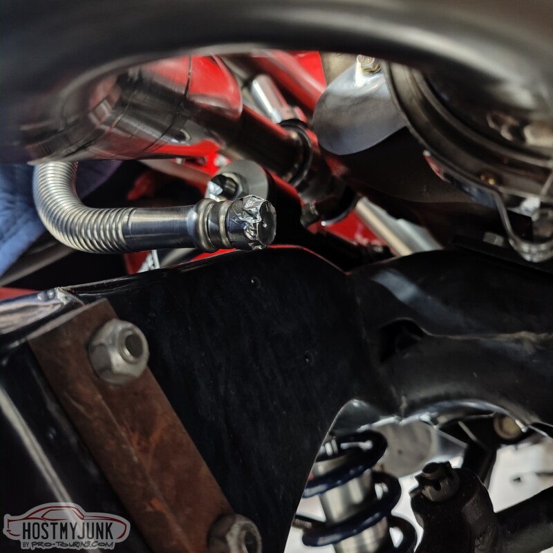
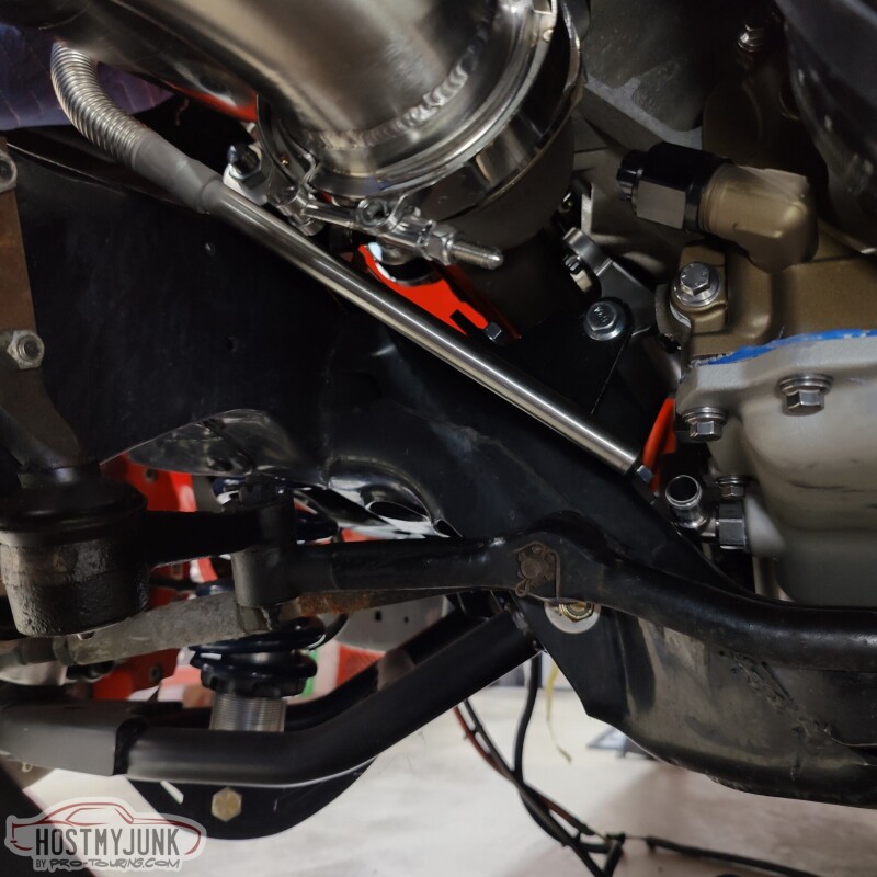
I also welded on this oil drain tube. Vic made a couple of adapters on the lathe and I welded it together. The welds are horrible, but it should hold. Because of how everything is situated, the drain has to take a slight jog to the passenger side immediately after coming out of the turbo. This is a turbo drain for a Cummins something or other. It is fairly flexible and is made out of stainless steel, so it is relatively easy to work with.
Once it makes the jog to the left is has to sweep right, under the up-pipe and under the exhaust manifold, then towards the drain in the side of the oil pan. I will extend this tube so it is all metal under the hottest pipes and there will be a short section of hose connecting the drain to the oil pan.
The waste gate discharge is tacked to the downpipe.
The downpipe itself is also tacked in place.
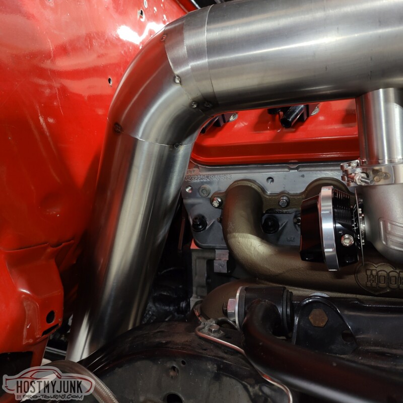
There is also a 4" v-band at the end of the downpipe that connects to this pipe that shoots the exhaust straight back.
I am not sure yet what's going to happen with the exhaust once it is past the transmission crossmember.
Andrew
Yesterday I received the last few parts that I needed to finish the new brake lines from the MC to the distribution block.
I also welded on this oil drain tube. Vic made a couple of adapters on the lathe and I welded it together. The welds are horrible, but it should hold. Because of how everything is situated, the drain has to take a slight jog to the passenger side immediately after coming out of the turbo. This is a turbo drain for a Cummins something or other. It is fairly flexible and is made out of stainless steel, so it is relatively easy to work with.
Once it makes the jog to the left is has to sweep right, under the up-pipe and under the exhaust manifold, then towards the drain in the side of the oil pan. I will extend this tube so it is all metal under the hottest pipes and there will be a short section of hose connecting the drain to the oil pan.
The waste gate discharge is tacked to the downpipe.
The downpipe itself is also tacked in place.
There is also a 4" v-band at the end of the downpipe that connects to this pipe that shoots the exhaust straight back.
I am not sure yet what's going to happen with the exhaust once it is past the transmission crossmember.
Andrew
TECH Apprentice


Joined: Jan 2015
Posts: 313
Likes: 127
From: Austin area
Nice progress. Couple questions:
1. Where did you get your shifter. I ordered the same one last month and was told it's back-ordered and won't ship out until the 17th
2. Do you need to put heat shielding on the oil drain? Looks awful close to the exhaust. I don't know much about turbo setups, so this is more of an education for me.
3. Excited to see how the elec brakes work. Not great looking, but probably WAY easier that plumbing hydroboost. Where did you get the idea and what is the booster off of (sorry if you said this already and I missed it)?
Thanks,
Jim
Thread Starter
Joined: Mar 2003
Posts: 10,617
Likes: 1,883
From: Little Austin
Nice progress. Couple questions:
1. Where did you get your shifter. I ordered the same one last month and was told it's back-ordered and won't ship out until the 17th
2. Do you need to put heat shielding on the oil drain? Looks awful close to the exhaust. I don't know much about turbo setups, so this is more of an education for me.
3. Excited to see how the elec brakes work. Not great looking, but probably WAY easier that plumbing hydroboost. Where did you get the idea and what is the booster off of (sorry if you said this already and I missed it)?
Thanks,
Jim
1. Where did you get your shifter. I ordered the same one last month and was told it's back-ordered and won't ship out until the 17th
2. Do you need to put heat shielding on the oil drain? Looks awful close to the exhaust. I don't know much about turbo setups, so this is more of an education for me.
3. Excited to see how the elec brakes work. Not great looking, but probably WAY easier that plumbing hydroboost. Where did you get the idea and what is the booster off of (sorry if you said this already and I missed it)?
Thanks,
Jim
The exhaust will be shielded as will the oil drain.
I actually like the way the iBooster looks. It goes the engine bay a modern, high tech look. This booster is from an early Tesla model S with the adaptive cruise control option.
There are many other cars that use the iBooster with different shapes of reservoirs. There are also two generation of iBooster models. I don't know what the differences are. I chose this one strictly based on looks and my thinking that it would be easiest to adapt.
Andrew
TECH Apprentice
Joined: Jan 2015
Posts: 313
Likes: 127
From: Austin area
I got the shifter at Speedway Motors, about 6 months ago.
The exhaust will be shielded as will the oil drain.
I actually like the way the iBooster looks. It goes the engine bay a modern, high tech look. This booster is from an early Tesla model S with the adaptive cruise control option.
There are many other cars that use the iBooster with different shapes of reservoirs. There are also two generation of iBooster models. I don't know what the differences are. I chose this one strictly based on looks and my thinking that it would be easiest to adapt.
Andrew

TECH Apprentice
Joined: Sep 2012
Posts: 347
Likes: 66
From: Tucson, AZ
Looking great! Do you know if the reservoirs and pushrods for the ibooster are interchangeable? IMO the one you have seems the best looking/most functional.
All the non-Tesla I boosters are quite a bit cheaper which is why I am asking. Definitely interested in this before these boosters get too expensive. When you factor in the price of a good booster/master cylinder, the price isn't bad. Thanks!
All the non-Tesla I boosters are quite a bit cheaper which is why I am asking. Definitely interested in this before these boosters get too expensive. When you factor in the price of a good booster/master cylinder, the price isn't bad. Thanks!
Last edited by Novapat67; Jan 14, 2023 at 02:01 PM.
Thread Starter
Joined: Mar 2003
Posts: 10,617
Likes: 1,883
From: Little Austin
Looking great! Do you know if the reservoirs and pushrods for the ibooster are interchangeable? IMO the one you have seems the best looking/most functional.
All the non-Tesla I boosters are quite a bit cheaper which is why I am asking. Definitely interested in this before these boosters get too expensive. When you factor in the price of a good booster/master cylinder, the price isn't bad. Thanks!
All the non-Tesla I boosters are quite a bit cheaper which is why I am asking. Definitely interested in this before these boosters get too expensive. When you factor in the price of a good booster/master cylinder, the price isn't bad. Thanks!
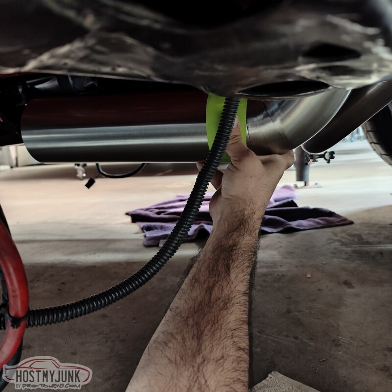
Today's update is a bit random because we kind of jumped around doing various tasks. Since the brake lines were done, I figured it was about time to see if the iBooster actually works ad if we can bled the brakes.
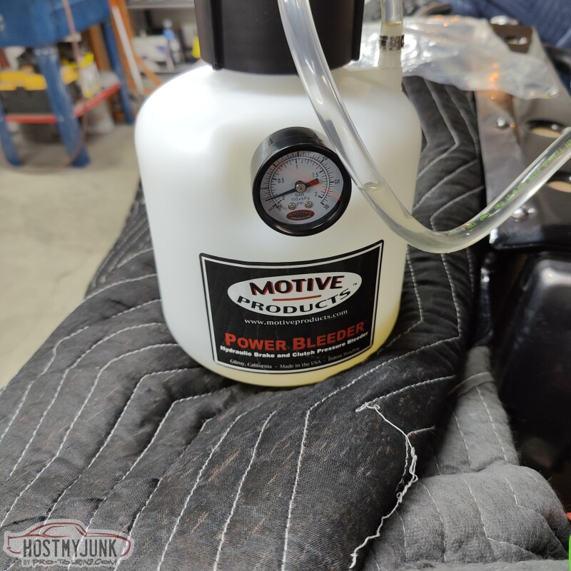
I have heard a lot of good things about the Motive Products brake bleeders, so I thought I would get one to try. I have to say that I will never bleed brakes any other way. The process was super simple and I barely spilled any brake fluid.
I got the version of the Motive brake blender that came with a MC cap that was compatible with the Tesla MC cap. It also works on many newer GM cars.
While I wasn't around, Vic changed the angle of the downpipe a little bit to move it a little further from the firewall. There is a little over an inch now.
Yesterday I also finished up the turbo oil drain pipe by welding on an extension that will feed the drain under the turbo hot parts and feed into the oil pan.
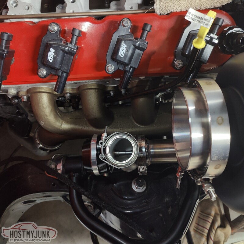
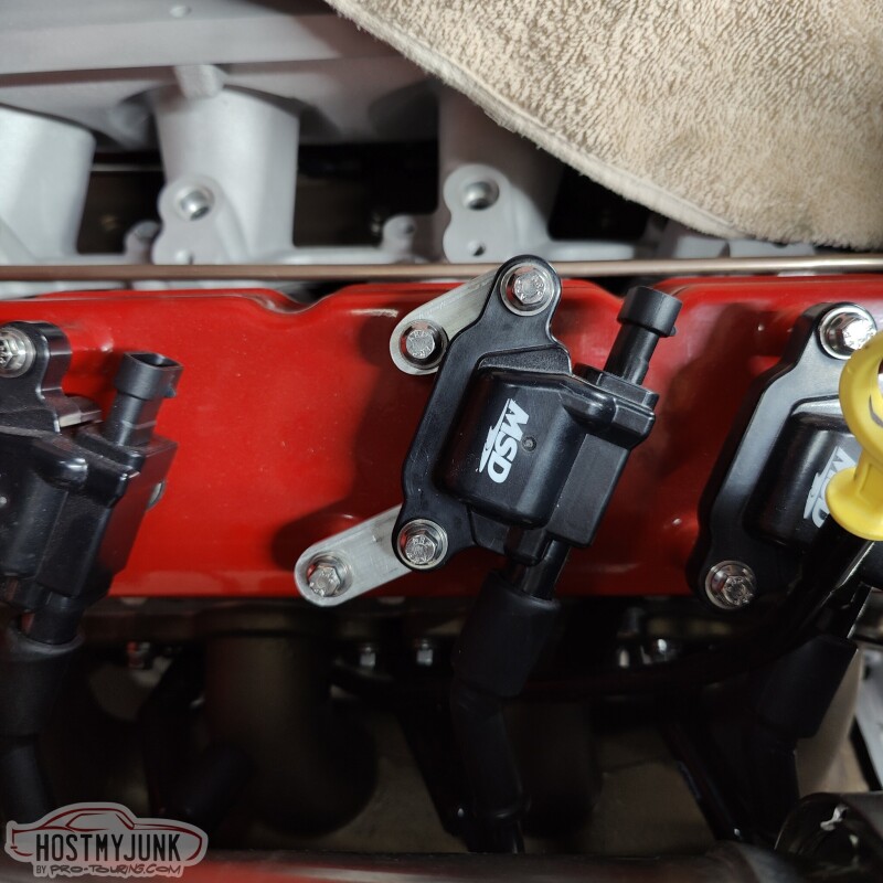
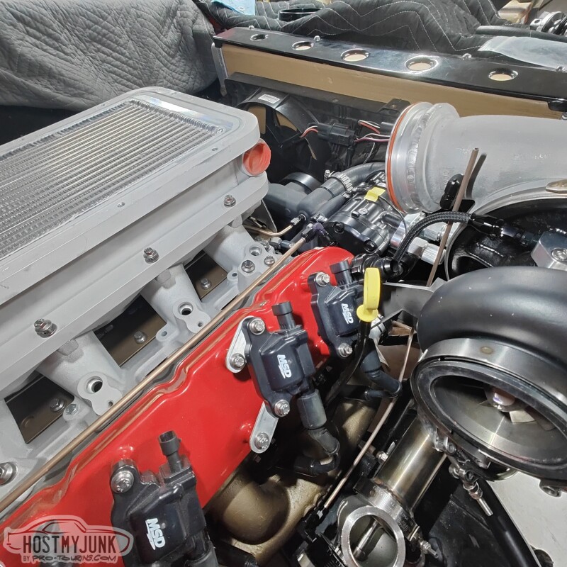
Vic also made these little tabs that position the coils a little higher and over. This was done to move the spark plug wires away from the downpipe.
Andrew
LS1 Tech Stories
The Best V8 Stories One Small Block at Time

Topdon ONE vs. Artidiag 800 BT2: Which is the Diagnostic Tablet For You?
Pouria Savadkouei
Gas Monkey Built a 6-Wheel Ferrari Testarossa With a Corvette LT4 Engine
Verdad Gallardo
7 Most Reliable High-Performance Engines GM Has Ever Built
Verdad Gallardo
Amazing '71 Camaro Restomod Is Modern Muscle Car Under the Skin
Verdad Gallardo
6 Common C5 Corvette Failures and What's Involved In Repairing Them
Pouria Savadkouei
Retro Modern Bandit Pontiac Trans AM Comes With Burt Reynolds' Autograph
Verdad Gallardo
Top 10 Greatest Cadillac V Series Performance Models Ever, Ranked
Pouria Savadkouei
Top 10 Most Powerful Chevy Trucks Ever Made!

Hennessey's New Supercharged Silverado ZR2 Has 700 HP
Verdad Gallardo TECH Apprentice
Joined: Sep 2012
Posts: 347
Likes: 66
From: Tucson, AZ
I agree about the reservoirs. They all look strangely thin and low with a weird shape except this one. The reason I was asking about the pushrods is because the Chevy Bolt version of the ibooster is way cheaper but has a ball at the end of the pushrod rather than a clevis.
That bleeder looks sweet!
That bleeder looks sweet!
Thread Starter
Joined: Mar 2003
Posts: 10,617
Likes: 1,883
From: Little Austin
I agree about the reservoirs. They all look strangely thin and low with a weird shape except this one. The reason I was asking about the pushrods is because the Chevy Bolt version of the ibooster is way cheaper but has a ball at the end of the pushrod rather than a clevis.
That bleeder looks sweet!
That bleeder looks sweet!
https://www.ebay.com/itm/33466842536...Bk9SR7SNp4m3YQ
The part with the ball on the end screws off, just like the clevis did on the Tesla booster. We cut the Tesla clevis off and welded a 3/8" grade 8 bolt to the short section that screws on the iBooster pushrod and the original clevis screws on the bolt with a jam nut.
Andrew
Thread Starter
Joined: Mar 2003
Posts: 10,617
Likes: 1,883
From: Little Austin
Before talking about today's update, I realized that I really didn't mention how the iBooster feels. After bleeding the brakes, we powered up the iBooster and it just started working. The pedal effort is pretty light, but very smooth. Pedal travel is also fairly short before the pedal gets really hard to press. As of now I think the driving experience is going to be greatly improved over the manual brakes that I had before.
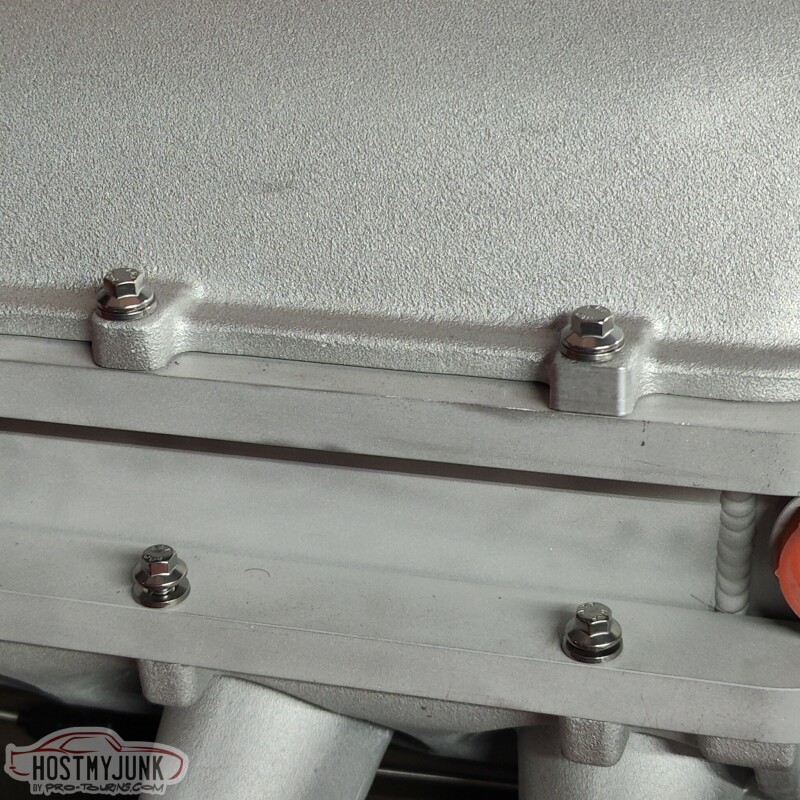
Today's update is also just a random collection of small projects. Last week I ordered all new ARP hardware for the intake lid and the intercooler. The included hardware was adequate, but silver cad plated bolts tend to look like garbage after a very short time. The ARP stainless hardware will look great for a long time.
I also finished installing the new, collapsable steering shaft and new u-joints from Borgeson.
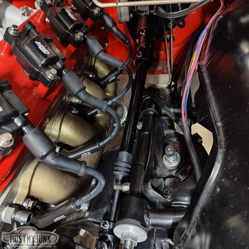
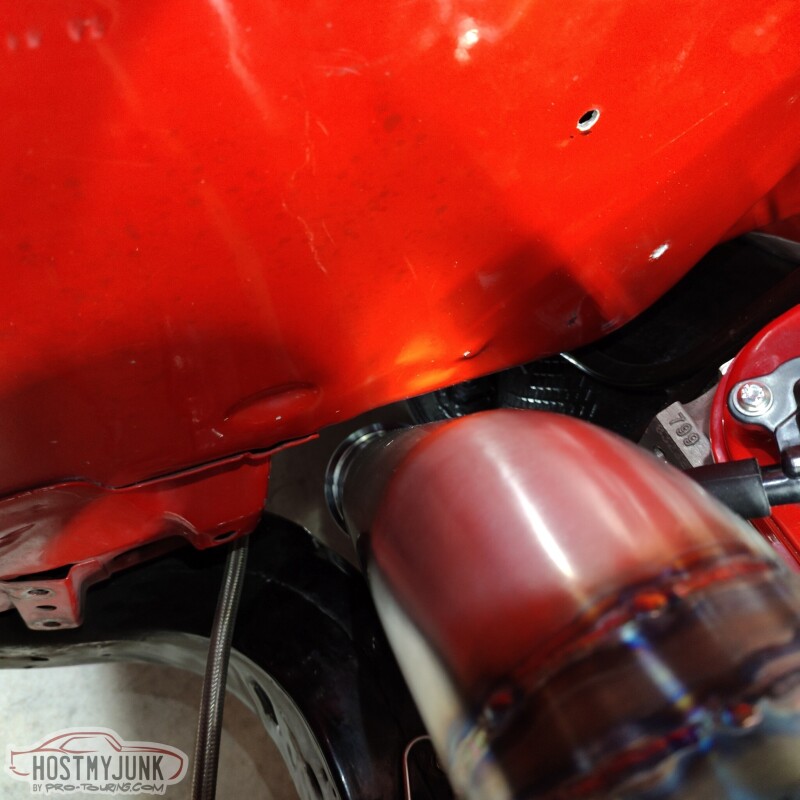
I also finished up the oil drain for the turbo. Here is how it wraps around the up-pipe.
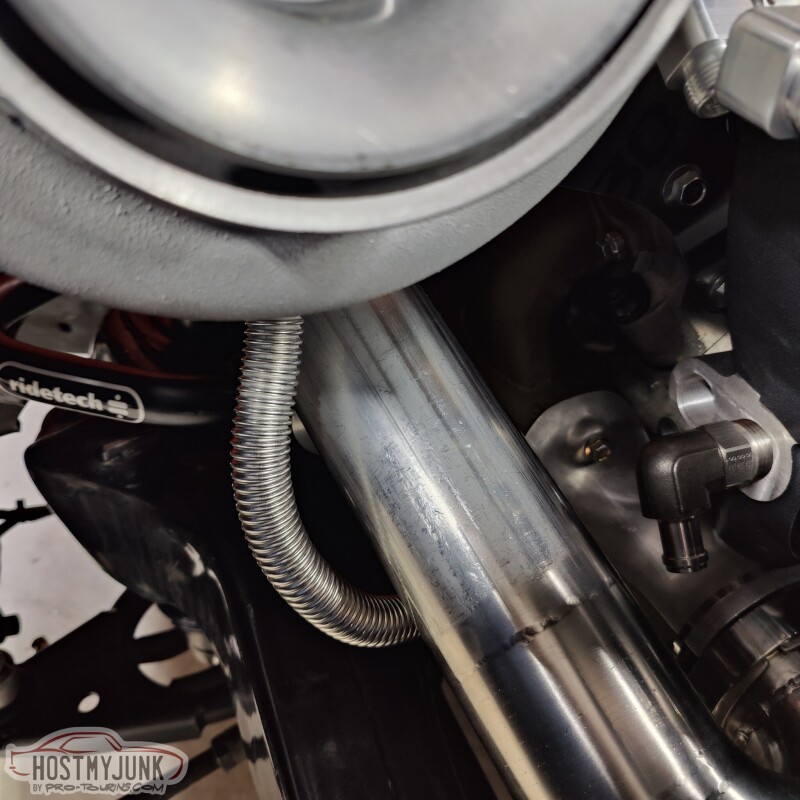
Then it goes under all of the turbo hot pipes, pointing at the fitting in the oil pan.
The only thing left is to put a bead on the 5/8" tube and add a short length of rubber hose between the tube and the oil pan fitting.
Lastly, I have been doing a lot of looking and thinking about where to mount the boost control solenoids. There is quite a bit of plumbing that needs to go between the wastegate, turbo compressor outlet, and the boost solenoids. I want to keep that plumbing as short and simple as possible, so I am thinking about making a bracket and mounting them under the nose of the intake lid.
This location will make the plumbing relatively short and keep the solenoids relatively hidden.
Andrew
Today's update is also just a random collection of small projects. Last week I ordered all new ARP hardware for the intake lid and the intercooler. The included hardware was adequate, but silver cad plated bolts tend to look like garbage after a very short time. The ARP stainless hardware will look great for a long time.
I also finished installing the new, collapsable steering shaft and new u-joints from Borgeson.
I also finished up the oil drain for the turbo. Here is how it wraps around the up-pipe.
Then it goes under all of the turbo hot pipes, pointing at the fitting in the oil pan.
The only thing left is to put a bead on the 5/8" tube and add a short length of rubber hose between the tube and the oil pan fitting.
Lastly, I have been doing a lot of looking and thinking about where to mount the boost control solenoids. There is quite a bit of plumbing that needs to go between the wastegate, turbo compressor outlet, and the boost solenoids. I want to keep that plumbing as short and simple as possible, so I am thinking about making a bracket and mounting them under the nose of the intake lid.
This location will make the plumbing relatively short and keep the solenoids relatively hidden.
Andrew
TECH Apprentice
Joined: Sep 2012
Posts: 347
Likes: 66
From: Tucson, AZ
The part with the ball on the end screws off, just like the clevis did on the Tesla booster. We cut the Tesla clevis off and welded a 3/8" grade 8 bolt to the short section that screws on the iBooster pushrod and the original clevis screws on the bolt with a jam nut.
Andrew
Andrew
Thread Starter
Joined: Mar 2003
Posts: 10,617
Likes: 1,883
From: Little Austin
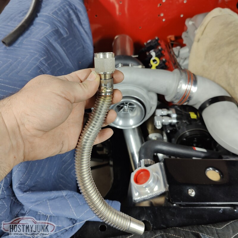
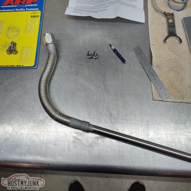
Today I got some PTFE hose and -4AN fittings and made the flex line for the turbo oil feed.
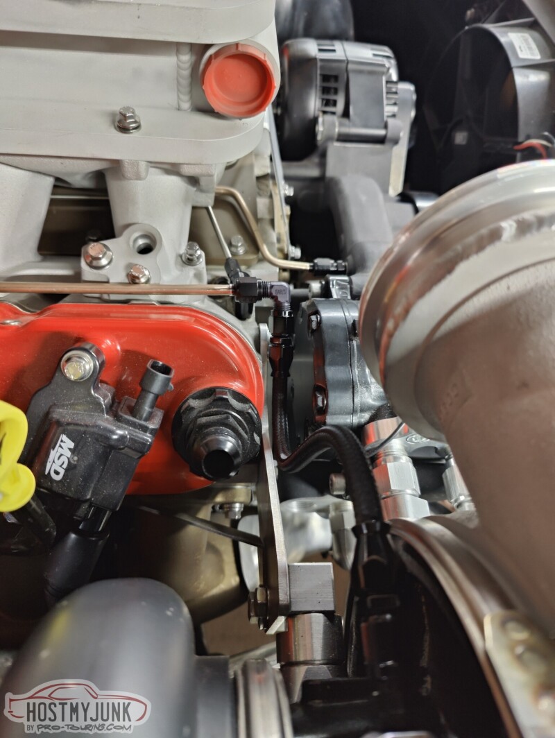
I gave it a nice, soft S-shape to keep it tucked away.
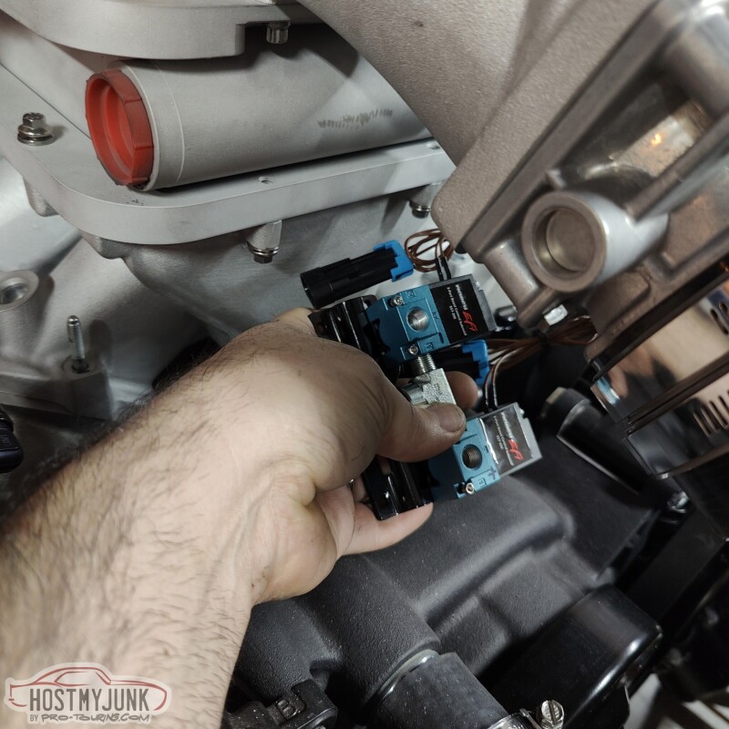
Vic made a little bracket to hold the boost solenoids just under the intake lid snout. The mounting points for the bracket have slots, so the bolts just need to be loosened up to put it on or remove it.
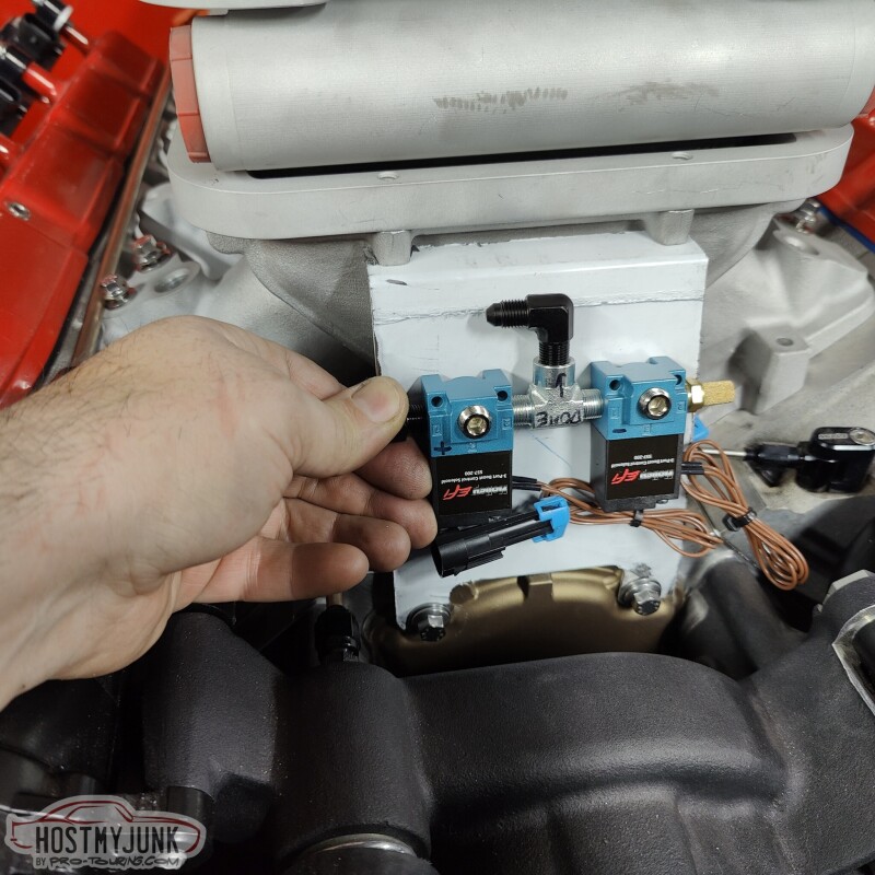
One of the big reasons for choosing this location and orientation is so that the two nipples face the general direction of the wastegate and turbo. One of the lines needs to go to the top of the wastage dome and the other needs to go to the turbo compressor discharge.
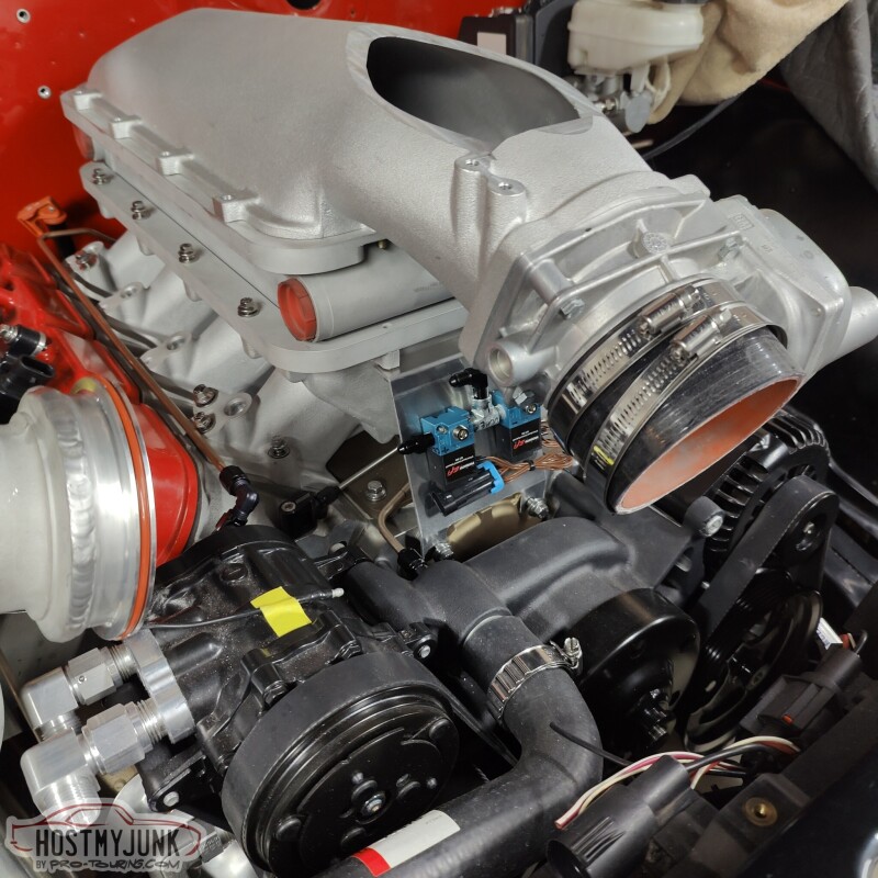
Here is the view from the other side. I am going to have my friend Blake design and print a cover for the solenoids.
Since the wastegate is not super accessible and is surrounded by hot parts, I decided to plumb everything going to it using NiCopp 3/16" tubing. That way I don't have to worry about melting through the typical nylon hose and push-lock fittings.
This is the line from the compressor discharge to the bottom of the dome.
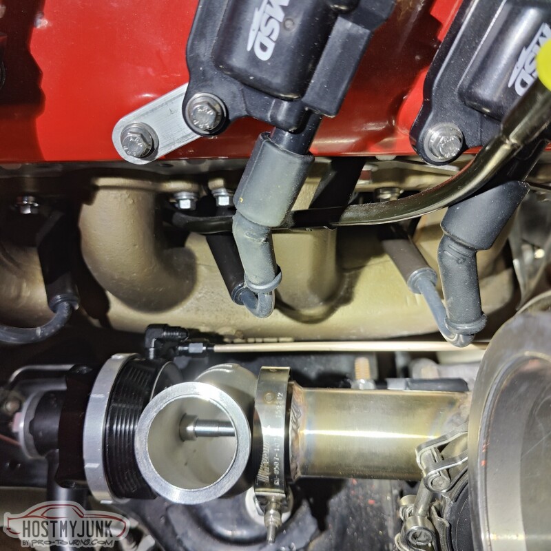
This TurboSmart wastegate has provisions for water cooling, so once the heater hose fittings are finalized, I will tap them and feet coolant to the dome of the wastegate.
Andrew


TECH Addict


Joined: Dec 2004
Posts: 2,178
Likes: 627
From: Florida
I agree about the reservoirs. They all look strangely thin and low with a weird shape except this one. The reason I was asking about the pushrods is because the Chevy Bolt version of the ibooster is way cheaper but has a ball at the end of the pushrod rather than a clevis.
That bleeder looks sweet!
That bleeder looks sweet!
id have driven it for the first time this weekend but my super fancy custom converter was customized for a different combo


Last edited by TrendSetter; Jan 17, 2023 at 07:41 AM.
Thread Starter
Joined: Mar 2003
Posts: 10,617
Likes: 1,883
From: Little Austin
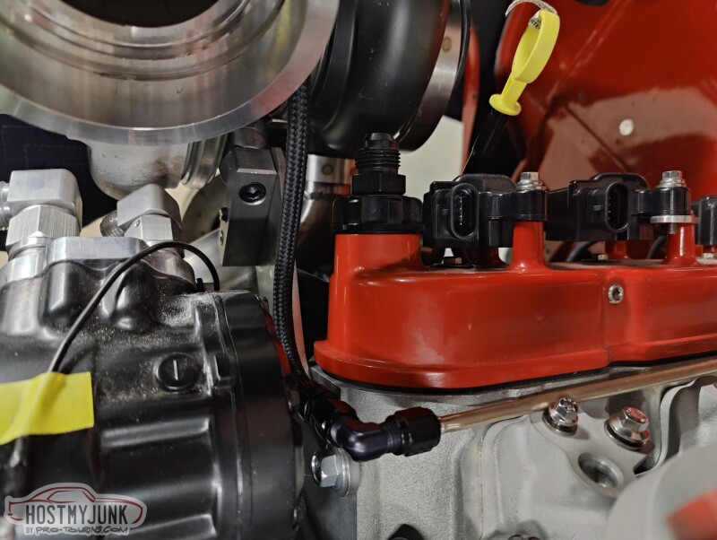
I try to do a little something everyday to keep making progress. We added a bung for the oxygen sensor. I wanted it easily accessible, but also not super visible.
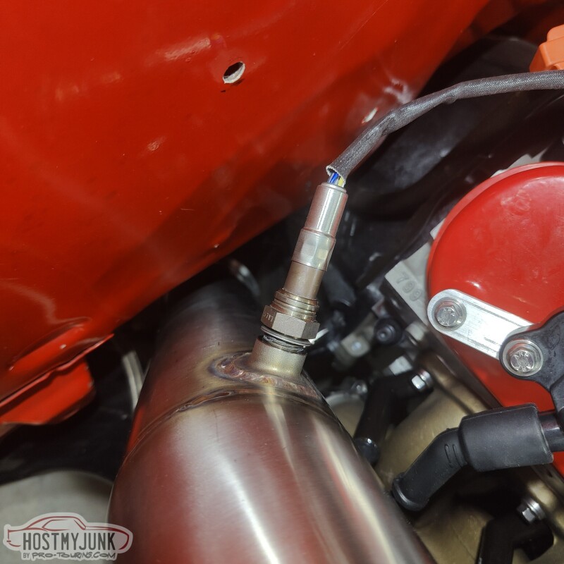
We also added a bung in the charge pipe and I added a small tube to feed boost pressure to the feed side of the boost solenoids.
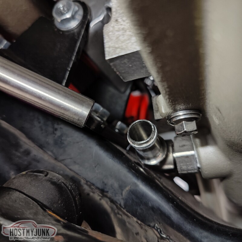
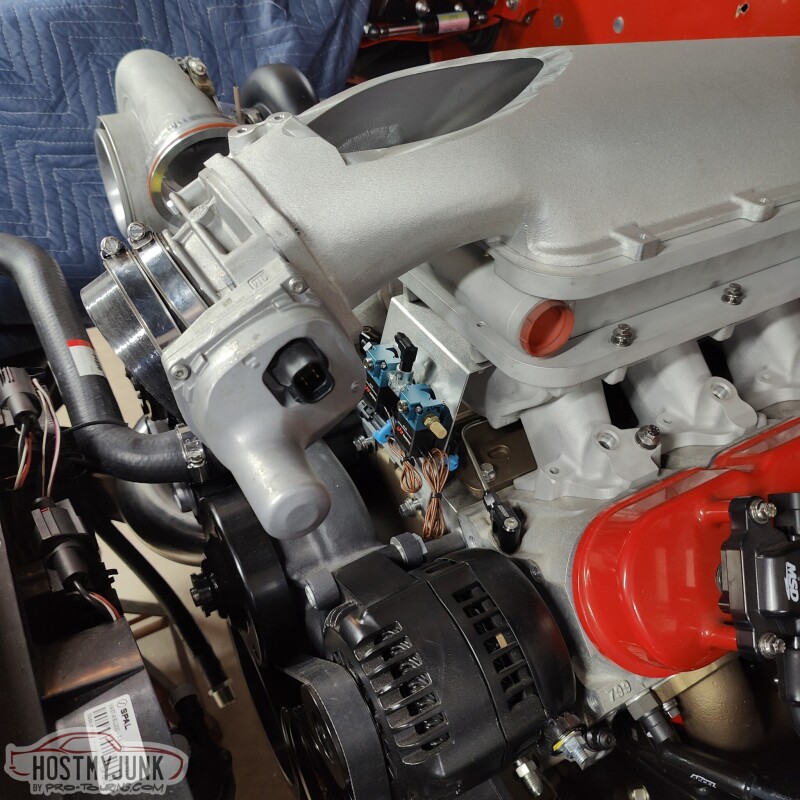
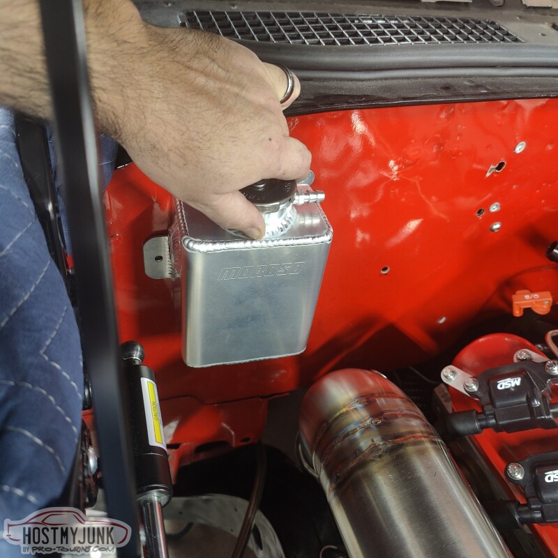
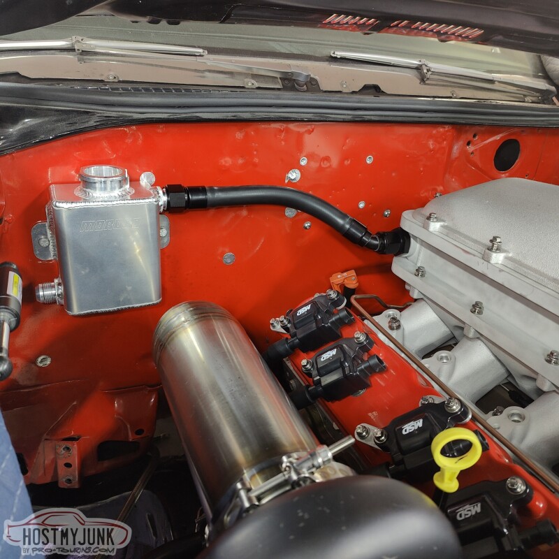
It was also time to think about where the fill tank for the A2W intercooler might go. I am thinking about this location on the firewall. I added a 45 degree fitting to the intercooler just to see how the hoses might be routed.
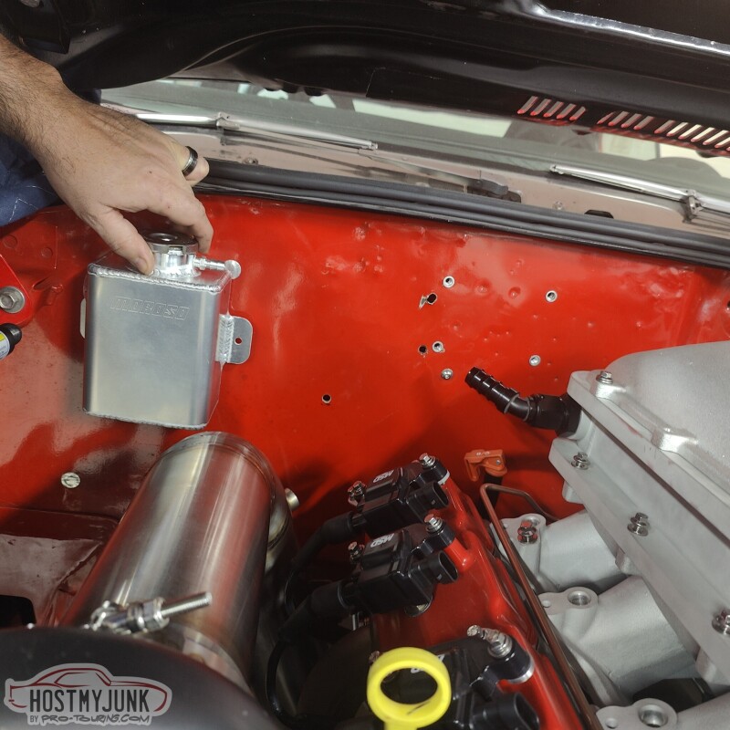
The tank looks like it is close to the downpipe, but there is actually quite a bit of space. The tank also needs to have a fill bung aded to the top of the right side and an outlet on the left side.
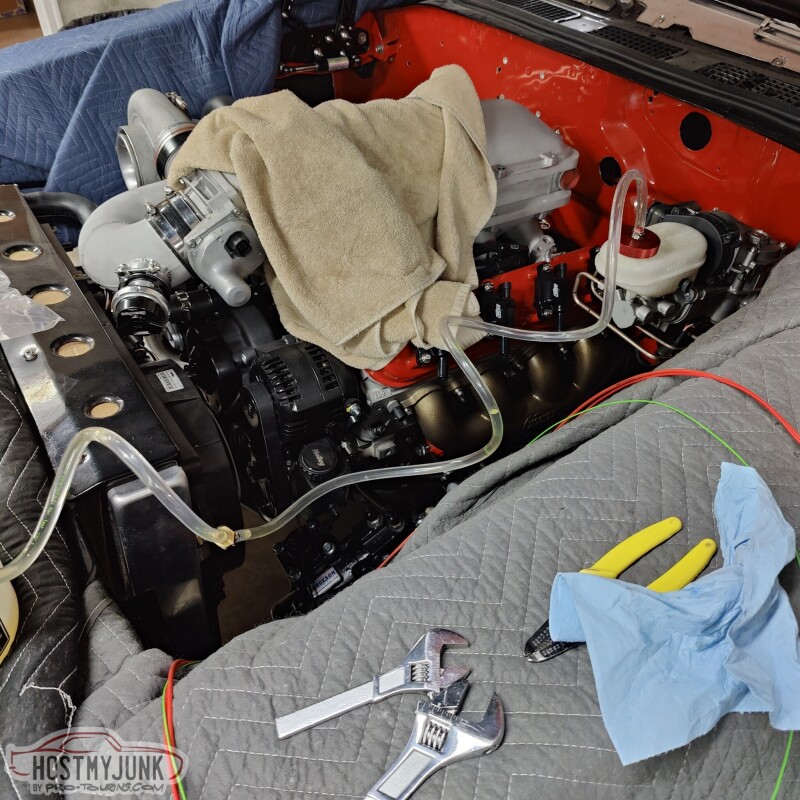
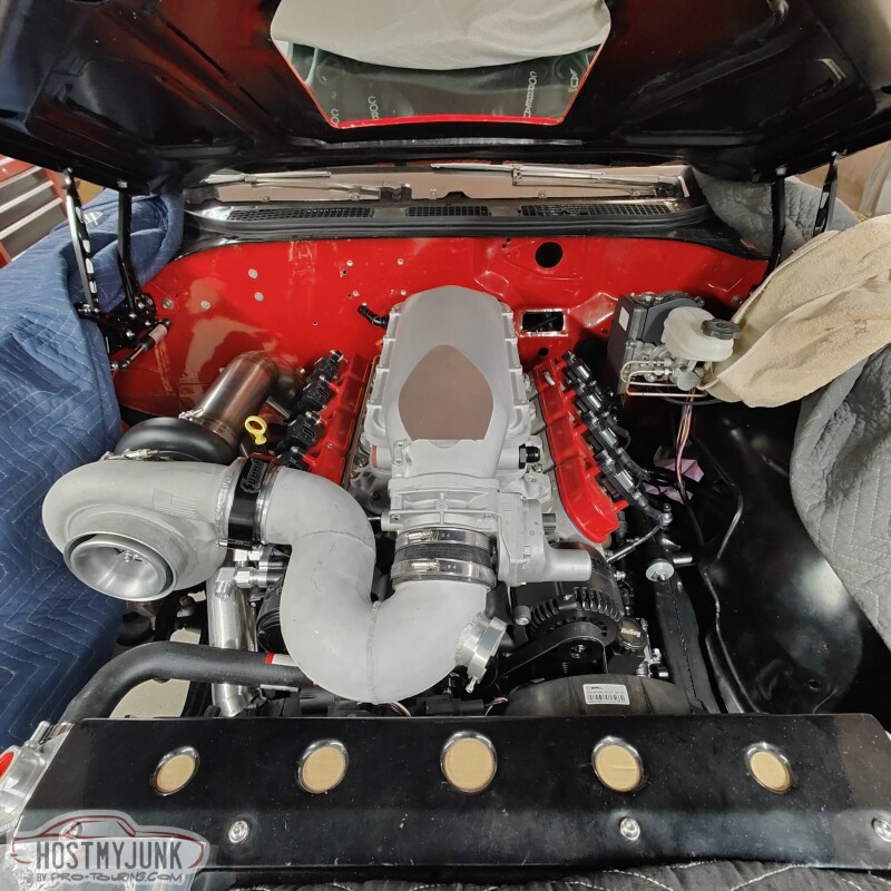
This is just an overall shot of the engine compartment as it sits now.
Baby steps...
Andrew
We also added a bung in the charge pipe and I added a small tube to feed boost pressure to the feed side of the boost solenoids.
It was also time to think about where the fill tank for the A2W intercooler might go. I am thinking about this location on the firewall. I added a 45 degree fitting to the intercooler just to see how the hoses might be routed.
The tank looks like it is close to the downpipe, but there is actually quite a bit of space. The tank also needs to have a fill bung aded to the top of the right side and an outlet on the left side.
This is just an overall shot of the engine compartment as it sits now.
Baby steps...
Andrew
Thread Starter
Joined: Mar 2003
Posts: 10,617
Likes: 1,883
From: Little Austin
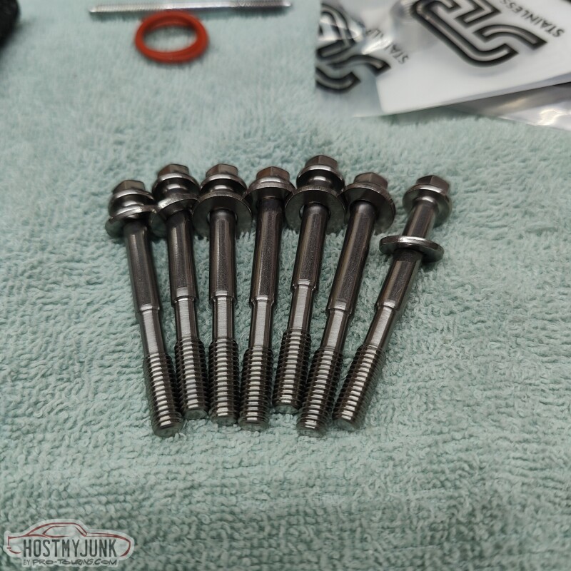
Since I am replacing all of the more visible fasteners on the engine with ARP stainless bolts, I wanted to replace the studs that Holley includes with the Low-Ram intake manifold. I carefully measured the needed length and it looked like ARP already had an intake bolt kit in that length (55mm UHL). Long story short, the ARP bolts didn't have the needed thread length to fully engage into the heads. Vic machined the shank of the bolts so they would torque down against the intake manifold.
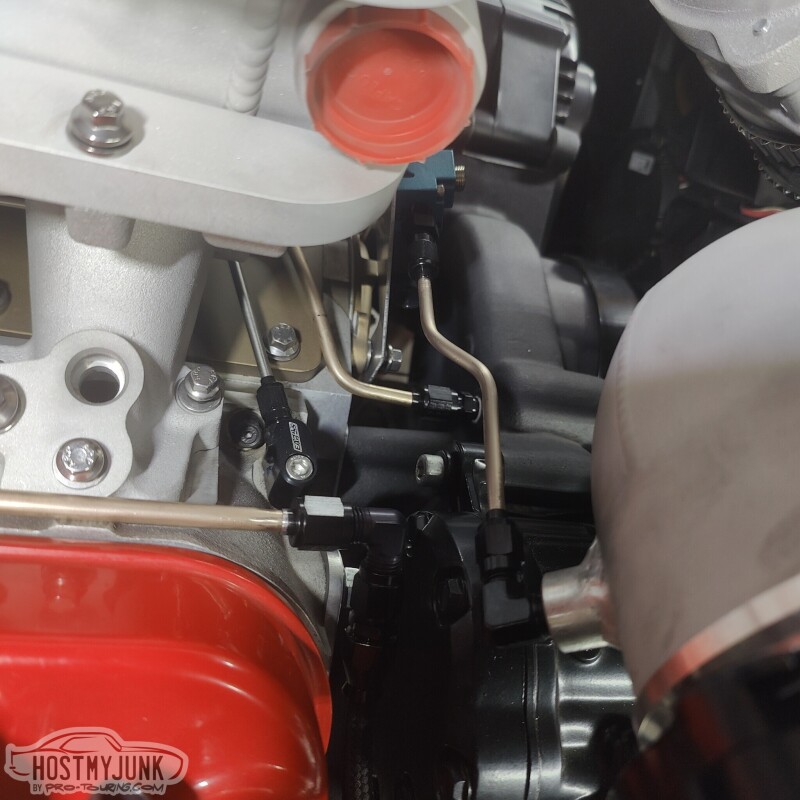
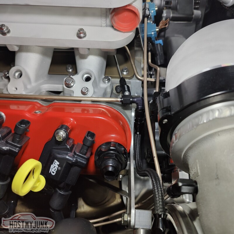
I also finished the last bit of NiCopp plumbing for the boost control systems. There is a tube from the turbo compressor to the bottom of the wastegate. There is another tube from the compressor to the fill side of the boost solenoids. Finally, there is a line from the boost solenoids to the top of the wastegate.
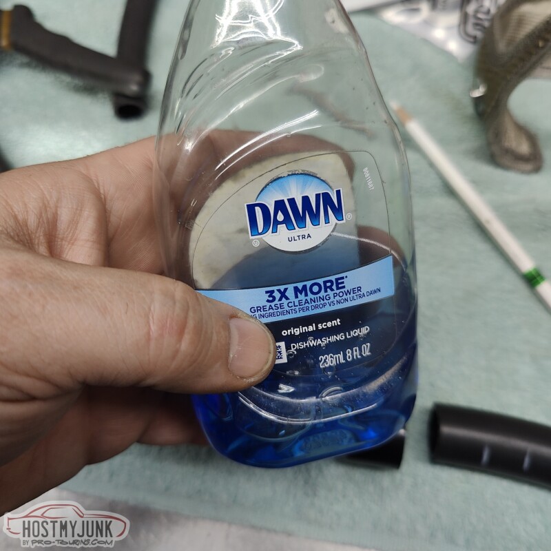
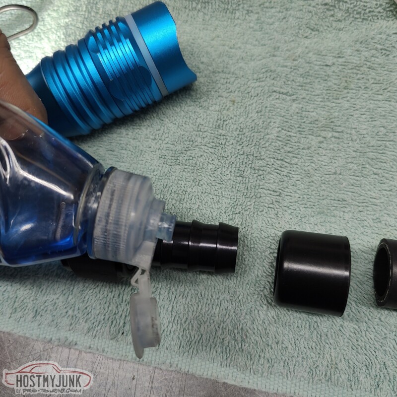
For the intercooler water hoses, I am using the Earl's Super Stock hose and swivel fittings. I have never used these before, but they work awesome. The ferrule spins over the hose to give the hose end a finished look.
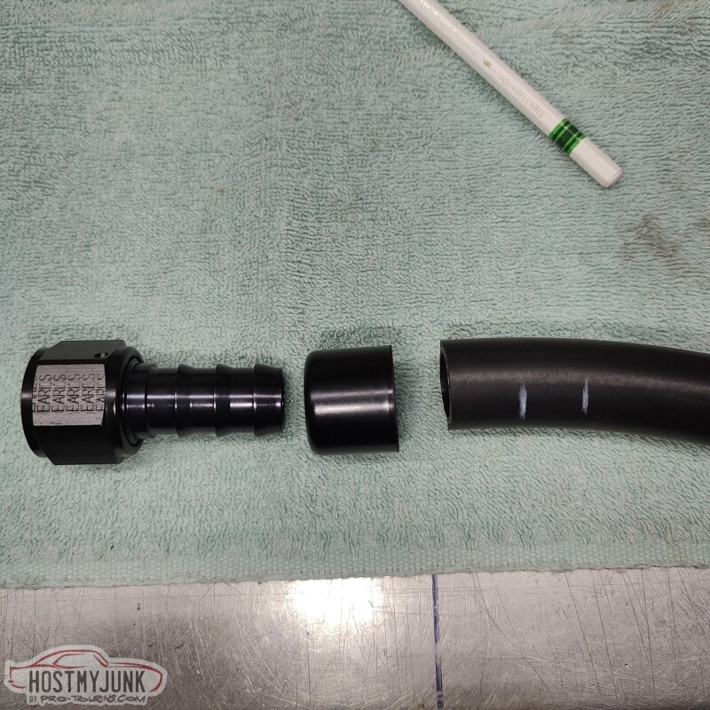
I used dish soap as a lubricant.
Little dab here...
Little dab there...and...
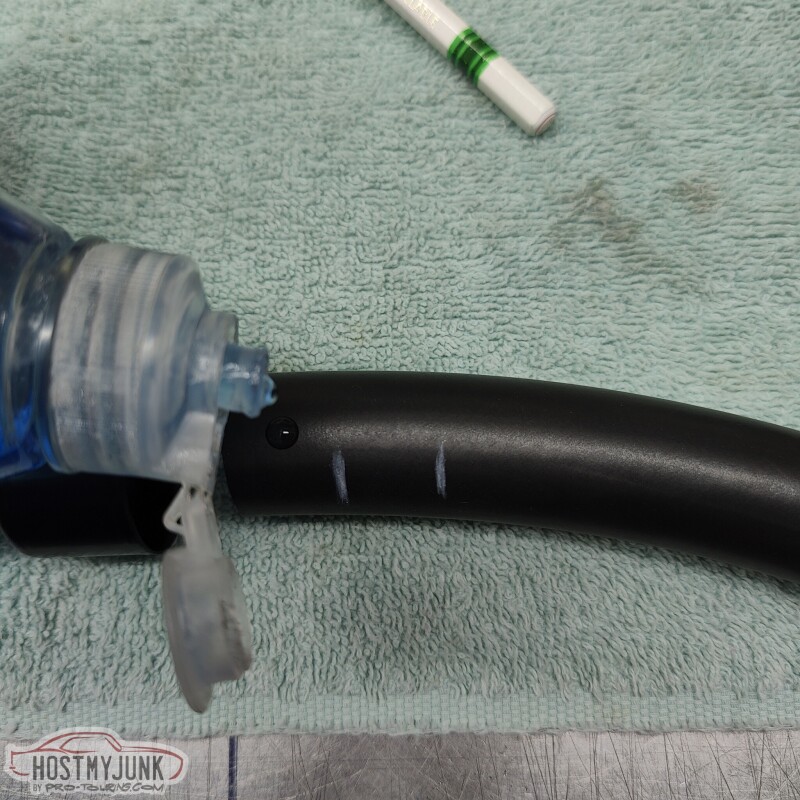
Viola!!!....oh, and Vic had already welded the fittings to the tank and mounted it with rivnuts.
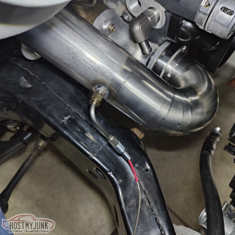
We also added an EGT probe just before the turbine housing.
Andrew
I also finished the last bit of NiCopp plumbing for the boost control systems. There is a tube from the turbo compressor to the bottom of the wastegate. There is another tube from the compressor to the fill side of the boost solenoids. Finally, there is a line from the boost solenoids to the top of the wastegate.
For the intercooler water hoses, I am using the Earl's Super Stock hose and swivel fittings. I have never used these before, but they work awesome. The ferrule spins over the hose to give the hose end a finished look.
I used dish soap as a lubricant.
Little dab here...
Little dab there...and...
Viola!!!....oh, and Vic had already welded the fittings to the tank and mounted it with rivnuts.
We also added an EGT probe just before the turbine housing.
Andrew

Thread Starter
Joined: Mar 2003
Posts: 10,617
Likes: 1,883
From: Little Austin