


1970 GTO Version 3.0
Joined: Apr 2006
Posts: 3,910
Likes: 1,158
From: Grand Rapids, Michigan
This is inspiring me to get my build going, although I'm nowhere near as far along as you are, Andrew. I have a question about that Motion Raceworks Flex Fuel sensor holder, or more accurately, about the placement of the sensor. If anyone is going to know the answer to this, it would be you. I would think that having the sensor closer to the engine would be advantageous because there's going to be a column of fuel in front of the sensor within the lines and fuel rails, etc. If you've been running 93 octane, and you run the tank nearly dry, if you add a tank of E85 and the sensor reads it almost immediately, won't that cause the PCM to switch to the E85 tables and create an overly rich mixture, if only momentarily? I understand fuel will be getting bypassed back to the tank, but how quickly does that occur? Sorry if this is a question with an obvious answer, I just plan to add E85 capability to my Firebird and want to make sure I do it correctly, the first time.
Thread Starter
Joined: Mar 2003
Posts: 10,617
Likes: 1,883
From: Little Austin
This is inspiring me to get my build going, although I'm nowhere near as far along as you are, Andrew. I have a question about that Motion Raceworks Flex Fuel sensor holder, or more accurately, about the placement of the sensor. If anyone is going to know the answer to this, it would be you. I would think that having the sensor closer to the engine would be advantageous because there's going to be a column of fuel in front of the sensor within the lines and fuel rails, etc. If you've been running 93 octane, and you run the tank nearly dry, if you add a tank of E85 and the sensor reads it almost immediately, won't that cause the PCM to switch to the E85 tables and create an overly rich mixture, if only momentarily? I understand fuel will be getting bypassed back to the tank, but how quickly does that occur? Sorry if this is a question with an obvious answer, I just plan to add E85 capability to my Firebird and want to make sure I do it correctly, the first time.
Andrew
Joined: Apr 2006
Posts: 3,910
Likes: 1,158
From: Grand Rapids, Michigan
Yeah, I kind of figured the conditions needing to be met for this to occur would be extremely unlikely, but it did make me wonder. I guess I'll just install mine whereever the best location ends up being and not worry too much about it. Thanks for the reply.
Thread Starter
Joined: Mar 2003
Posts: 10,617
Likes: 1,883
From: Little Austin
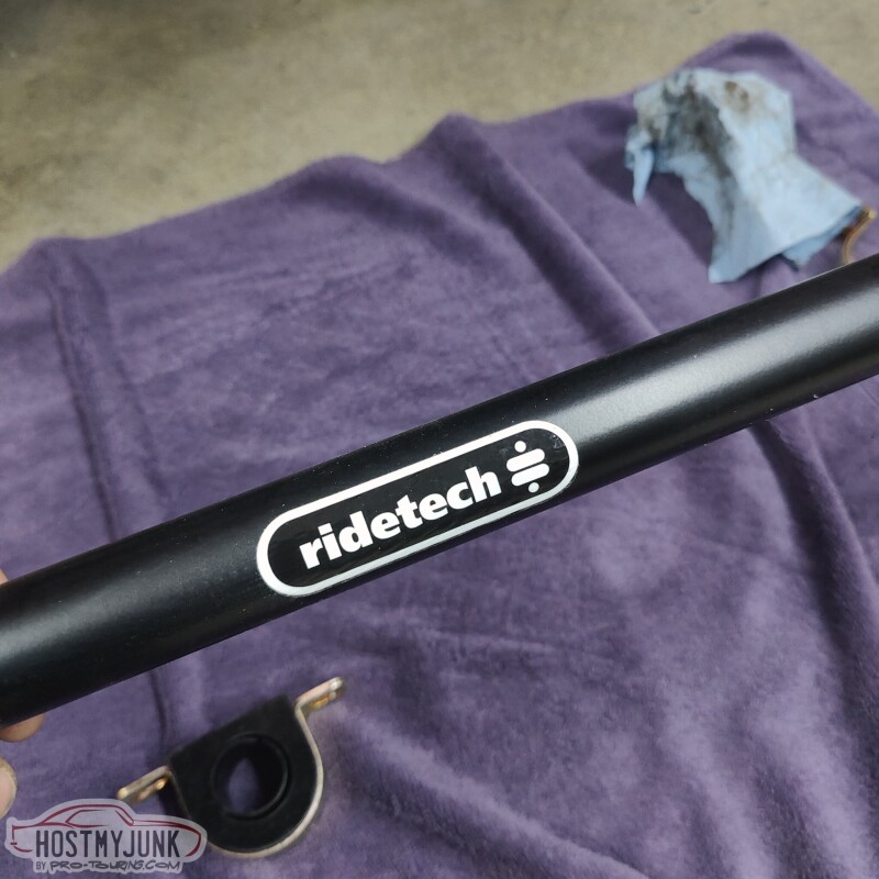
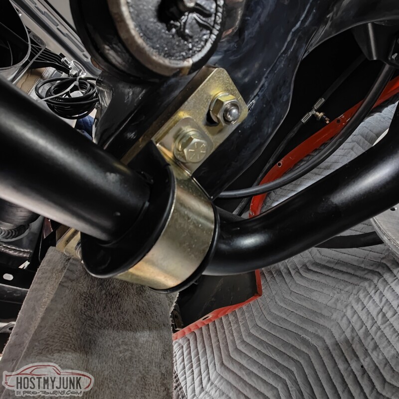
Today I decided to leave the plumbing for a while and tackle one of the last big boxes that I have. As mentioned before, this car now has a complete Ridetech suspension, front and rear, and part of that package are front and rear sway bars. This is the front sway bar.
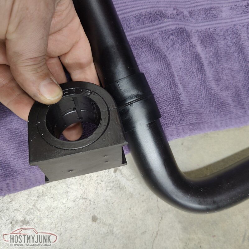
This sway bar kit is very thought out. The bushings are polyurethane, but they also include this slick Delrin bushing, which is supposed to eliminate the need for lube and is supposed to eliminate squeaks, which are so common with polyurethane bushings.
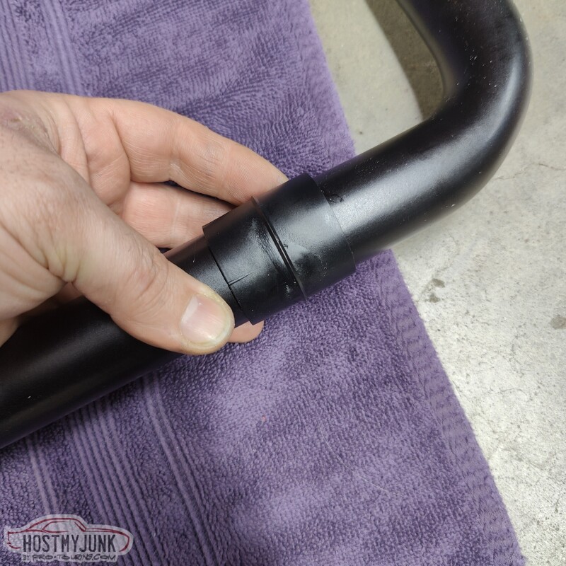
The ridge on the Delrin bushing rides inside a groove in the middle of the bushing, which keeps the bushing from sliding out.
Judging by the weight, the bar is hollow and has there bushing ends welded to both sides.
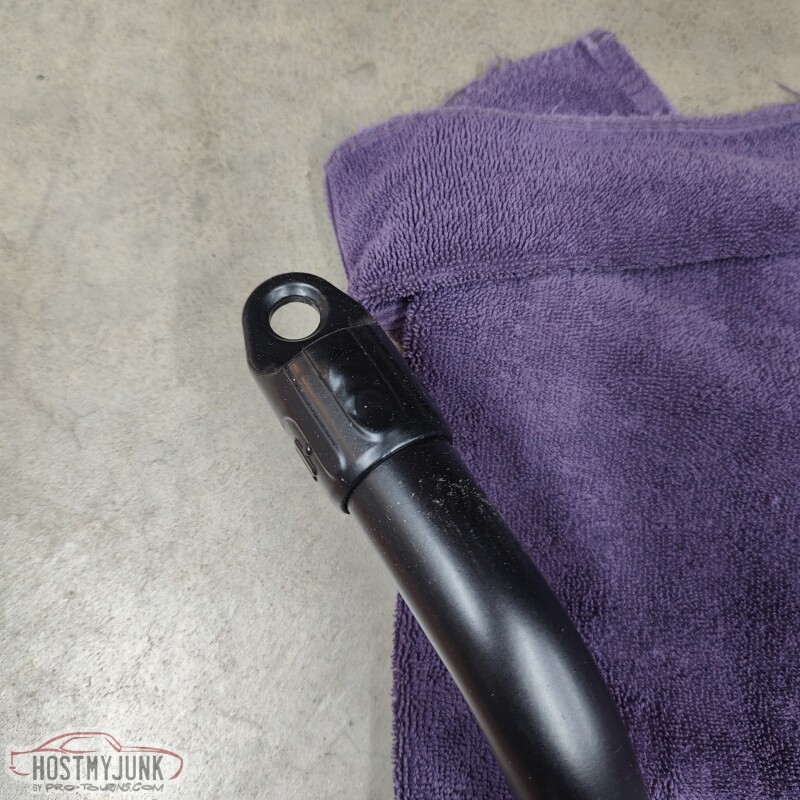
The mounting system includes some plates that move the bar about 1" forward. This is done to clear the pitman arm on the passenger side. My old swaybar used to rub a little bit against the edge of the pitman arm. You can see that now there is a solid inch of clearance.
The end links are Moog parts and also did not call for any lube.
Lastly, I also dug out the mating connectors for the bulkhead panel.
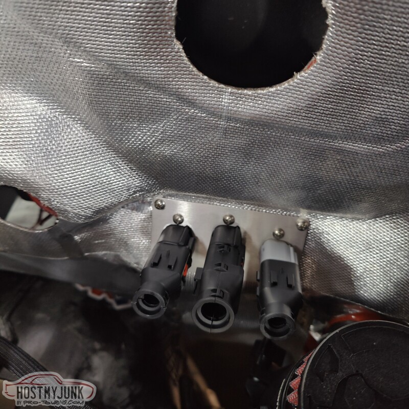
The connectors have the optional "backs" on them, so that I can fully cover the wires. The "backs" also provide addd strain relief, which is very important for all connectors.
Andrew
This sway bar kit is very thought out. The bushings are polyurethane, but they also include this slick Delrin bushing, which is supposed to eliminate the need for lube and is supposed to eliminate squeaks, which are so common with polyurethane bushings.
The ridge on the Delrin bushing rides inside a groove in the middle of the bushing, which keeps the bushing from sliding out.
Judging by the weight, the bar is hollow and has there bushing ends welded to both sides.
The mounting system includes some plates that move the bar about 1" forward. This is done to clear the pitman arm on the passenger side. My old swaybar used to rub a little bit against the edge of the pitman arm. You can see that now there is a solid inch of clearance.
The end links are Moog parts and also did not call for any lube.
Lastly, I also dug out the mating connectors for the bulkhead panel.
The connectors have the optional "backs" on them, so that I can fully cover the wires. The "backs" also provide addd strain relief, which is very important for all connectors.
Andrew
Thread Starter
Joined: Mar 2003
Posts: 10,617
Likes: 1,883
From: Little Austin
With spring quickly coming, my tuning business has been picking up steam, which means less time to work on the GTO, but I managed to knock out a couple of tasks.
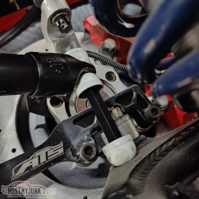
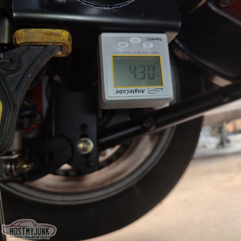
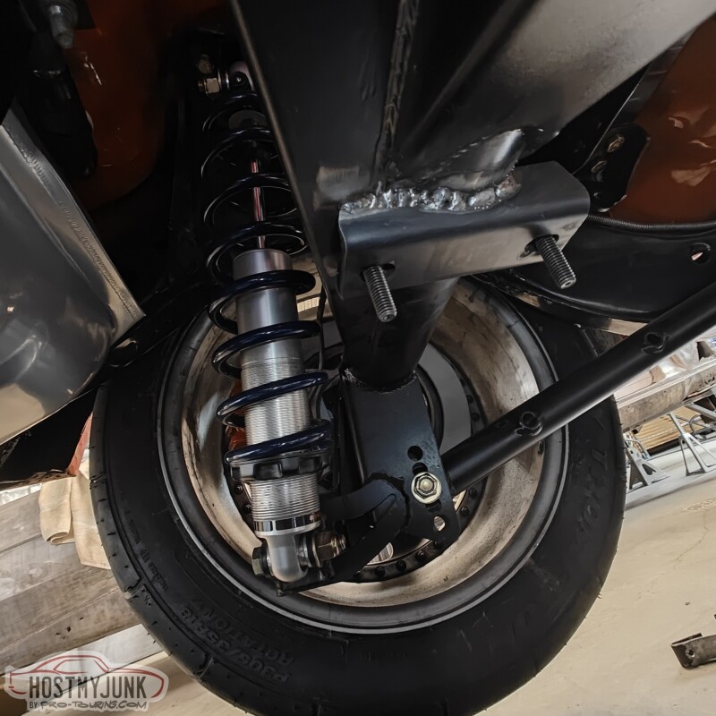
First up is the Ridetech rear sway bar. The kit comes with these brackets that would normally be held in place by a U-bolt. This this rear housing has a back brace, the bracket no longer fits around the axle tube. I trimmed the parts that were interfering and used an angle finder to make sure that both brackets were at the same angle. The actual angle is not critical, but having them be the same seemed pretty important.
Next, I drilled some holes in the frame for the end link brackets. This is the driver's wide.
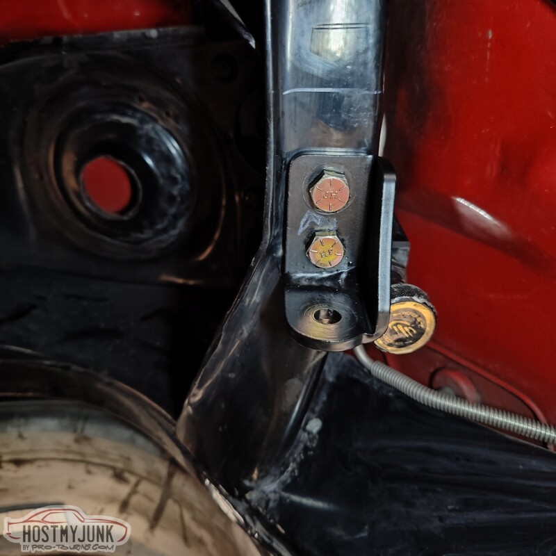
This is the passenger side with the sway bar bracket and the end link installed.
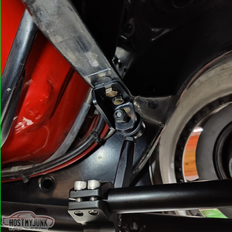
Vic got a new MIG welded and I buggered it in place. The welds are not pretty, but they will be fine.
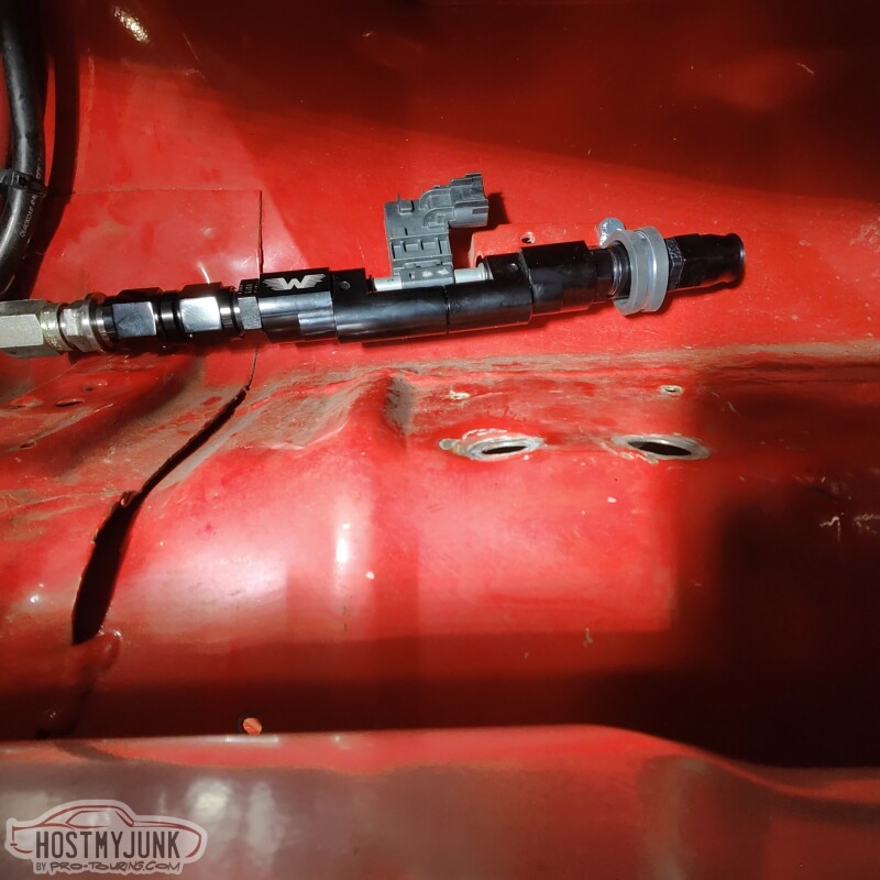
Lastly, fiddled around with the flex fuel sensor holder. I didn't want the sensor to just be hanging by the AN union without any support. I used a large P clamp to support the other side where the fuel line will attach.
Andrew
First up is the Ridetech rear sway bar. The kit comes with these brackets that would normally be held in place by a U-bolt. This this rear housing has a back brace, the bracket no longer fits around the axle tube. I trimmed the parts that were interfering and used an angle finder to make sure that both brackets were at the same angle. The actual angle is not critical, but having them be the same seemed pretty important.
Next, I drilled some holes in the frame for the end link brackets. This is the driver's wide.
This is the passenger side with the sway bar bracket and the end link installed.
Vic got a new MIG welded and I buggered it in place. The welds are not pretty, but they will be fine.
Lastly, fiddled around with the flex fuel sensor holder. I didn't want the sensor to just be hanging by the AN union without any support. I used a large P clamp to support the other side where the fuel line will attach.
Andrew
Thread Starter
Joined: Mar 2003
Posts: 10,617
Likes: 1,883
From: Little Austin
I take inspiration from all kinds of places. A while back I ran across a build on the Rad Rides website. It was the 1961 Brookwood wagon built for George Poteet:
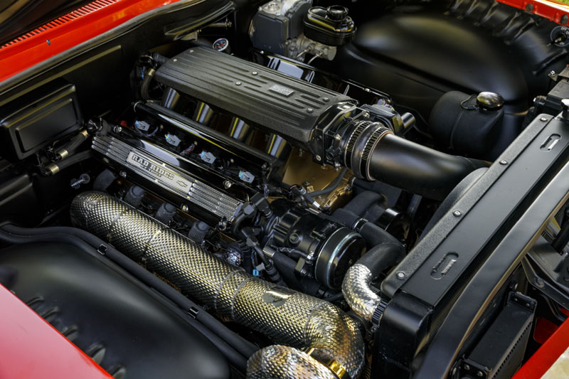
When I was at PRI I went to the booth of the vendor that did the cladding on the downpipe. The company is HeaderShield. I emailed them after the show, sent pictures of my parts, they gave me a quote, I paid it, sent my parts in, and ten weeks later I got them back.
This is the up-pipe that goes from the Holley manifold exit to the turbine inlet.
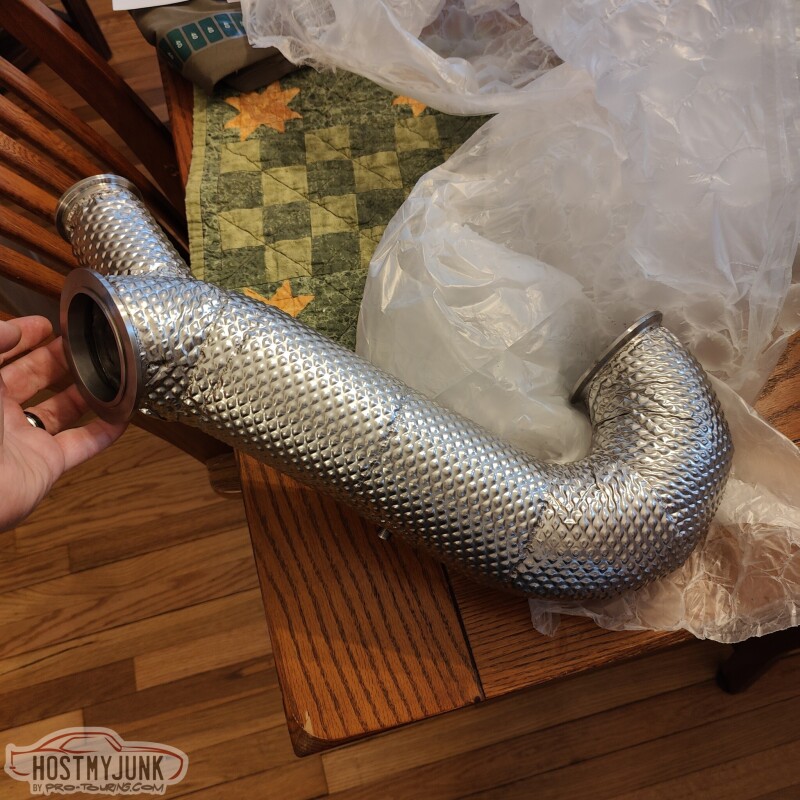
This is the downpipe that feeds the exhaust from the turbine, under the car.
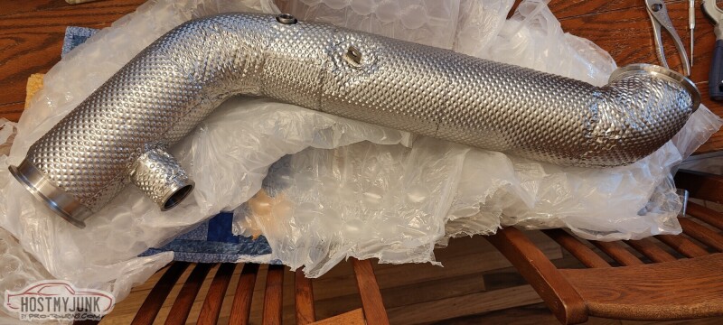
The rest of the exhaust will take off from the downpipe.
Andrew
When I was at PRI I went to the booth of the vendor that did the cladding on the downpipe. The company is HeaderShield. I emailed them after the show, sent pictures of my parts, they gave me a quote, I paid it, sent my parts in, and ten weeks later I got them back.
This is the up-pipe that goes from the Holley manifold exit to the turbine inlet.
This is the downpipe that feeds the exhaust from the turbine, under the car.
The rest of the exhaust will take off from the downpipe.
Andrew
Thread Starter
Joined: Mar 2003
Posts: 10,617
Likes: 1,883
From: Little Austin
LS1 Tech Stories
The Best V8 Stories One Small Block at Time

Gas Monkey Built a 6-Wheel Ferrari Testarossa With a Corvette LT4 Engine
Verdad Gallardo
7 Most Reliable High-Performance Engines GM Has Ever Built
Verdad Gallardo
Amazing '71 Camaro Restomod Is Modern Muscle Car Under the Skin
Verdad Gallardo
6 Common C5 Corvette Failures and What's Involved In Repairing Them
Pouria Savadkouei
Retro Modern Bandit Pontiac Trans AM Comes With Burt Reynolds' Autograph
Verdad Gallardo
Top 10 Greatest Cadillac V Series Performance Models Ever, Ranked
Pouria Savadkouei
Top 10 Most Powerful Chevy Trucks Ever Made!

Hennessey's New Supercharged Silverado ZR2 Has 700 HP
Verdad Gallardo
Coachbuilt N2A Anteros Is an LS2-Powered C6 Corvette In Italian Clothes
Verdad Gallardo Thread Starter
Joined: Mar 2003
Posts: 10,617
Likes: 1,883
From: Little Austin
I brought the pipes over to Vic's and installed them, hopefully for good. The downpipe fits great, although it is about 1/8 inch away from the frame. I am hoping the cladding will keep the powder coating on the frame from burning off.
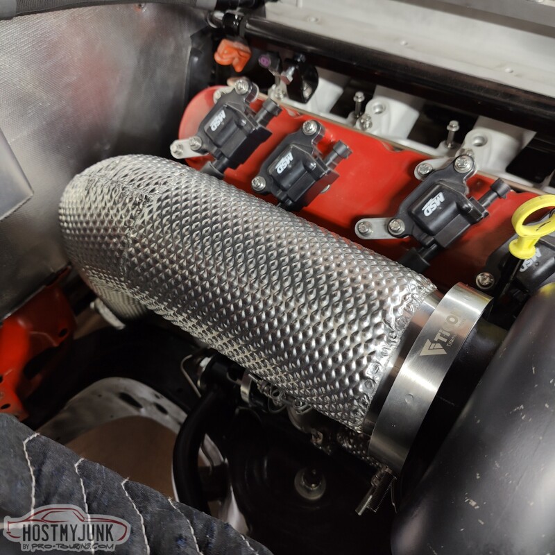
Here is the up-pipe, going from the Hooker exhaust manifold to the turbine inlet. If you look closely, you can see the bung for the EGT probe.
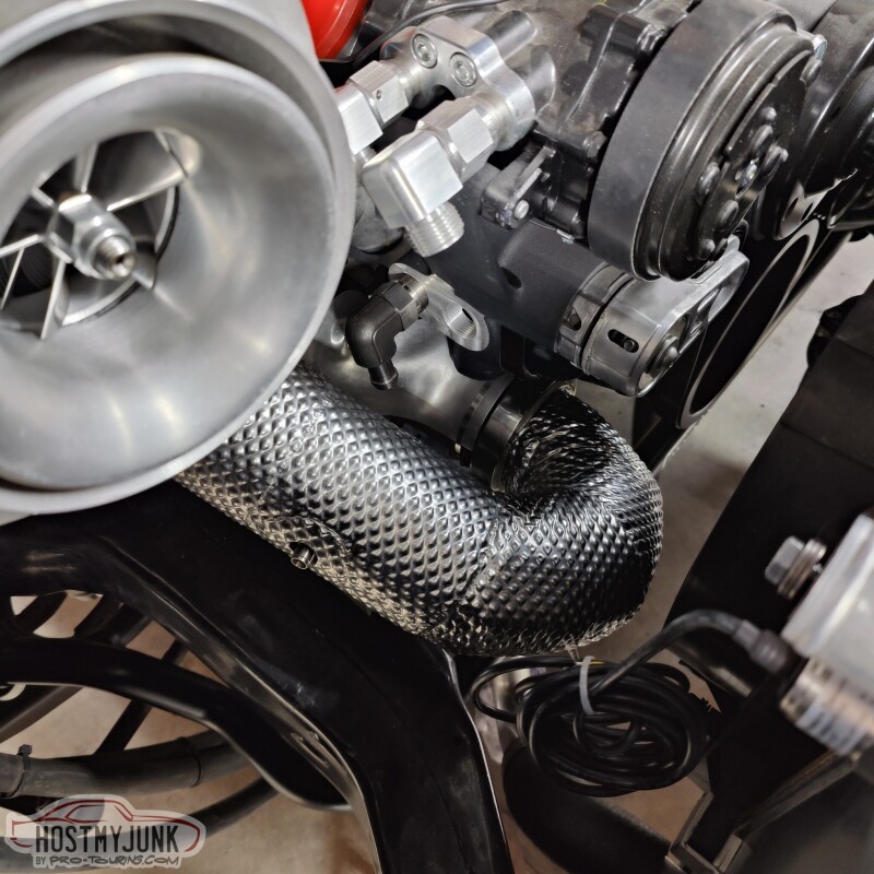
Here is the wastegate plumbing. The wastegate itself will get a little blanket, as will the turbine housing. Both from Funk Motorsports in England.
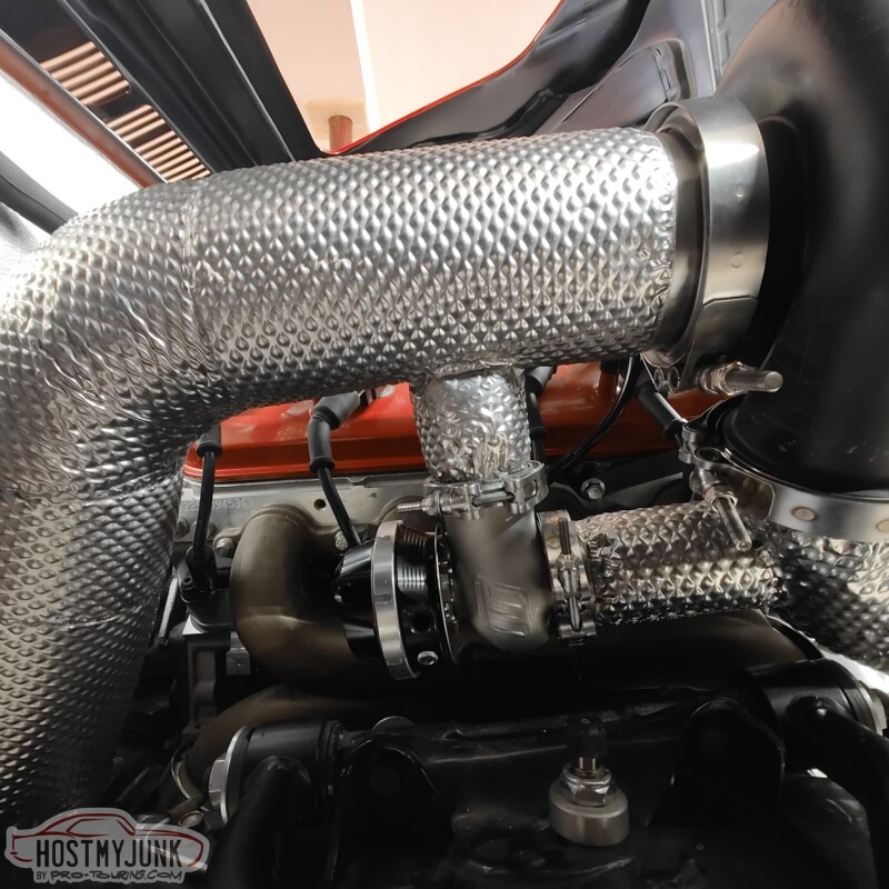
Here you can see the oil drain. Remember, it is stainless steel, but I also added an insulating sleeve over the top. The EGT bung is also clearly visible.
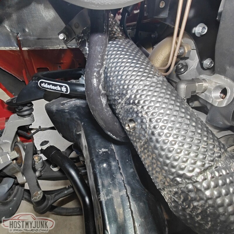
This is just an overall shot of how things are looking.
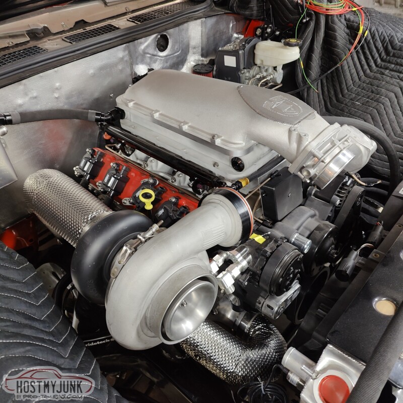
The yellow dipstick handle needs to go...
Andrew
Here is the up-pipe, going from the Hooker exhaust manifold to the turbine inlet. If you look closely, you can see the bung for the EGT probe.
Here is the wastegate plumbing. The wastegate itself will get a little blanket, as will the turbine housing. Both from Funk Motorsports in England.
Here you can see the oil drain. Remember, it is stainless steel, but I also added an insulating sleeve over the top. The EGT bung is also clearly visible.
This is just an overall shot of how things are looking.
The yellow dipstick handle needs to go...
Andrew


Thread Starter
Joined: Mar 2003
Posts: 10,617
Likes: 1,883
From: Little Austin
The whole area behind the rear seat was covered with MLV. It was sad to have to cut into it...
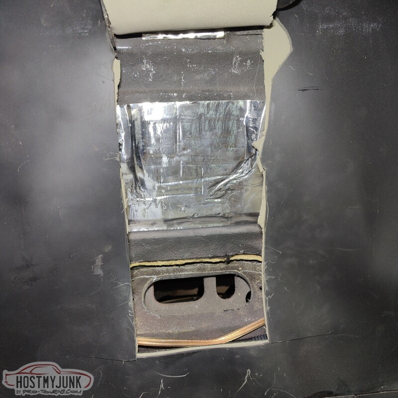
But I needed access so that I could install this...
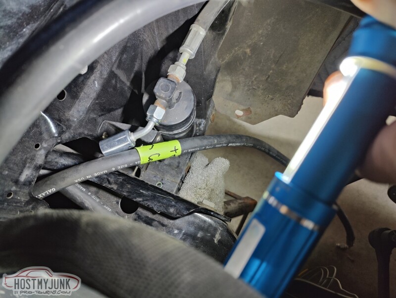
It is a OEM fuel vapor separator. I plan to vent the tank though this and then into a small charcoal canister. That should keep most of the fuel vapors at bay.
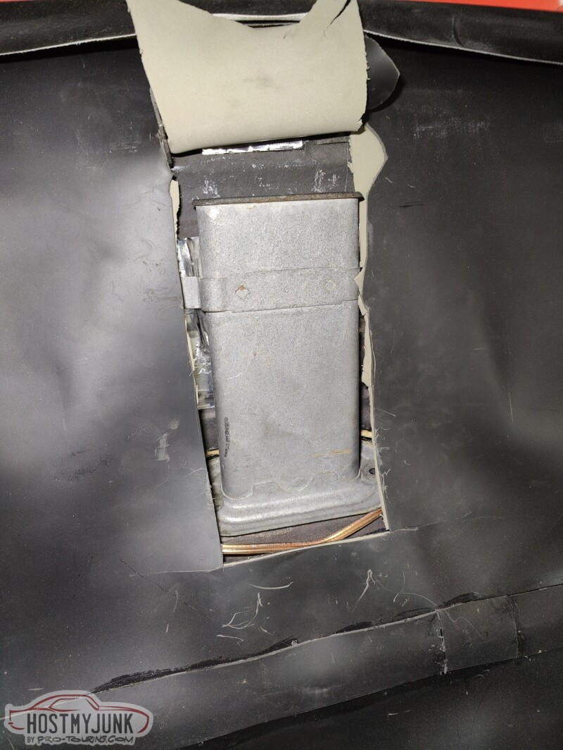
I sealed it against the body with some butyl rope.
Here you can see where the lines exit, just above the rear crossmember.
I also played around with the new gauges.
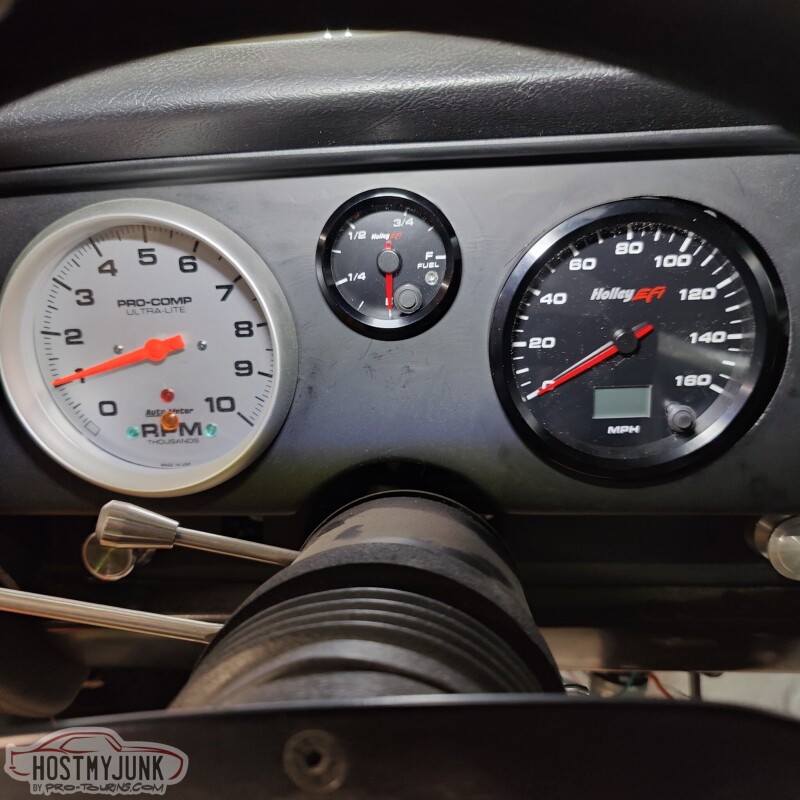
It is a little frustrating that the Holley gauges are 4" instead of 5", so something has to be done about that...The fuel lever gauge fit great into the 2 1/16" hole.
Andrew
But I needed access so that I could install this...
It is a OEM fuel vapor separator. I plan to vent the tank though this and then into a small charcoal canister. That should keep most of the fuel vapors at bay.
I sealed it against the body with some butyl rope.
Here you can see where the lines exit, just above the rear crossmember.
I also played around with the new gauges.
It is a little frustrating that the Holley gauges are 4" instead of 5", so something has to be done about that...The fuel lever gauge fit great into the 2 1/16" hole.
Andrew
TECH Apprentice


Joined: Jan 2015
Posts: 313
Likes: 127
From: Austin area
I brought the pipes over to Vic's and installed them, hopefully for good. The downpipe fits great, although it is about 1/8 inch away from the frame. I am hoping the cladding will keep the powder coating on the frame from burning off.
Here is the up-pipe, going from the Hooker exhaust manifold to the turbine inlet. If you look closely, you can see the bung for the EGT probe.
Here is the wastegate plumbing. The wastegate itself will get a little blanket, as will the turbine housing. Both from Funk Motorsports in England.
Here you can see the oil drain. Remember, it is stainless steel, but I also added an insulating sleeve over the top. The EGT bung is also clearly visible.
This is just an overall shot of how things are looking.
The yellow dipstick handle needs to go...
Andrew
Thread Starter
Joined: Mar 2003
Posts: 10,617
Likes: 1,883
From: Little Austin
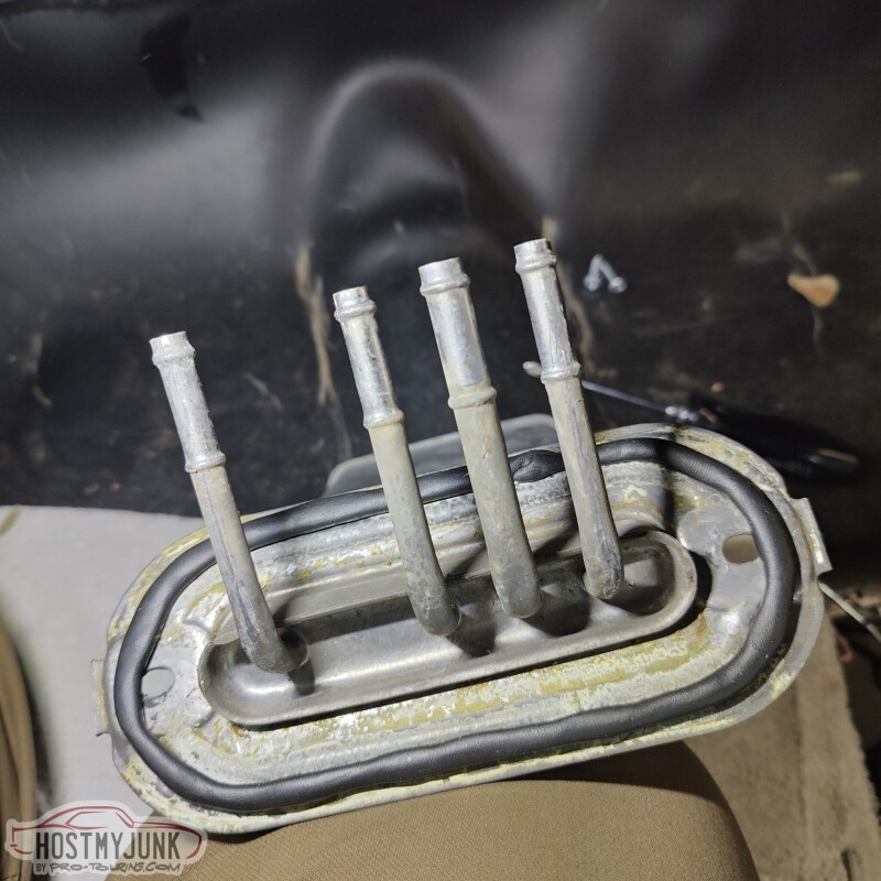
I like to repurpose OEM parts as part of my builds. I am not sure how I ran across this part, but it is from a 2008 Ford F250 with the PowerStroke engine.
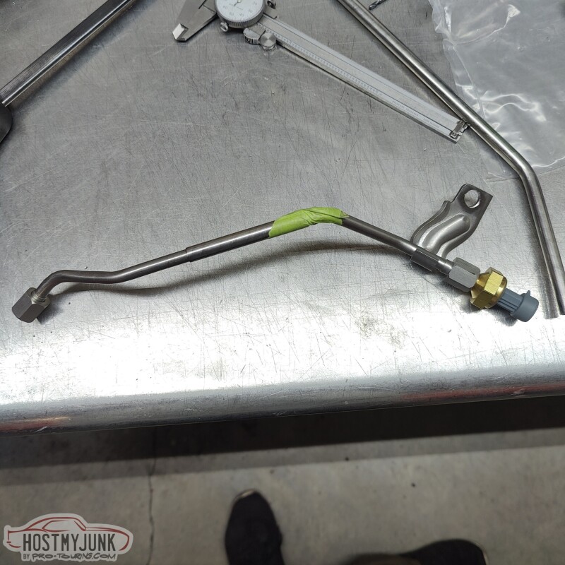
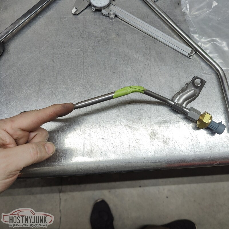
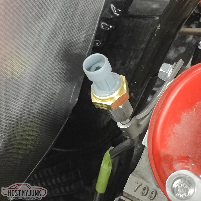
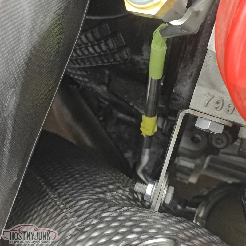
This is what Ford uses for the exhaust pressure sensor, and I figured I can use it for the same purpose. In this picture, the tube has been cut and a sleeve installed over the cut. The sleeve ends where the green tape is and where my finger is pointing.
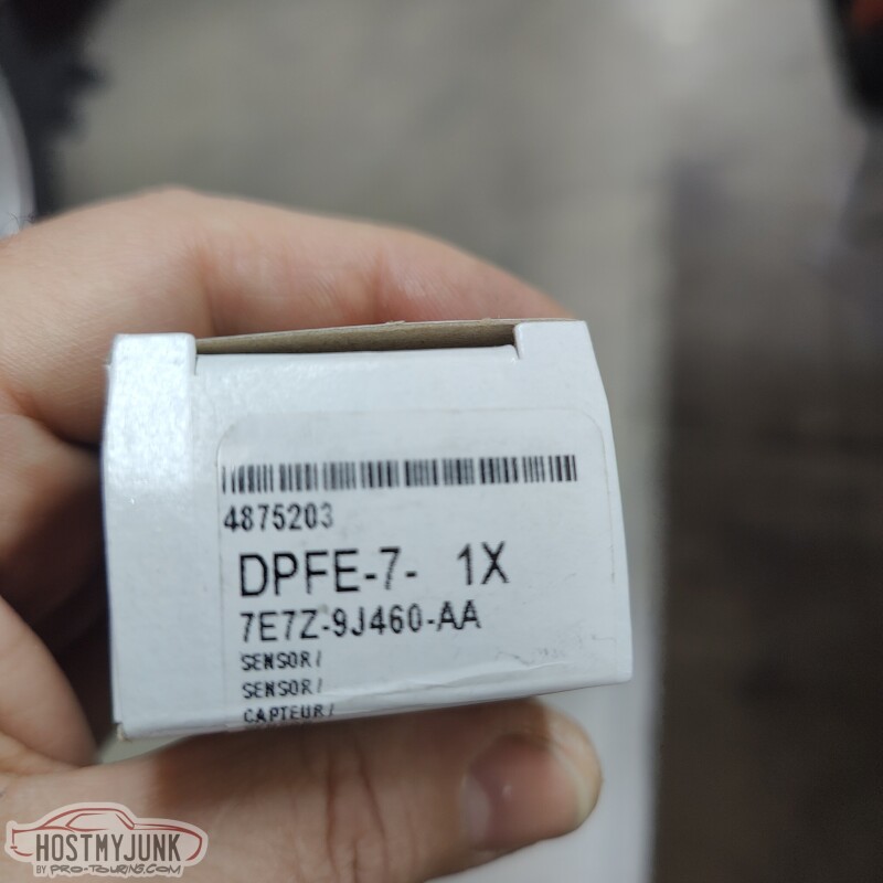
This is the sensor part number. From what I have been able to gather, it is a 0-54psi sensor.
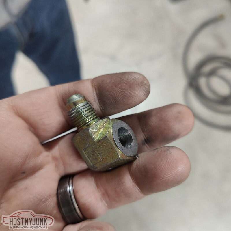
The tube is stainless and 5/16" diameter and it uses 37 degree flares with tube sleeves and nuts at both ends. That size tubing translates to an -AN5, which is not super common. Luckily, I had this 90 degree NPT to -AN5 adapter that I was using on the old tank for the return line. The NPT side has been cut off and Vic turned it down in the lathe to make a -AN5 male weld fitting.
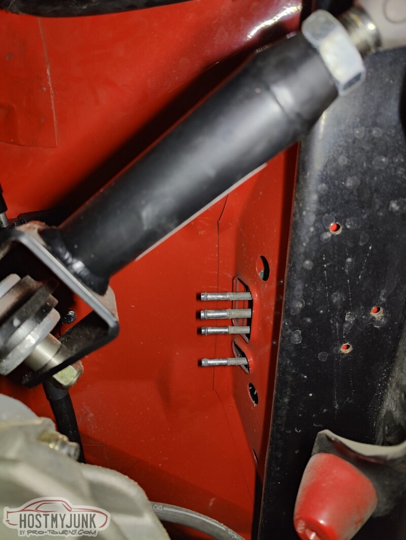
Here you can see where the fitting is going to go. Yes, the first hole was way off...
The whole assembly is bolted to one of the holes on the back of the heads...
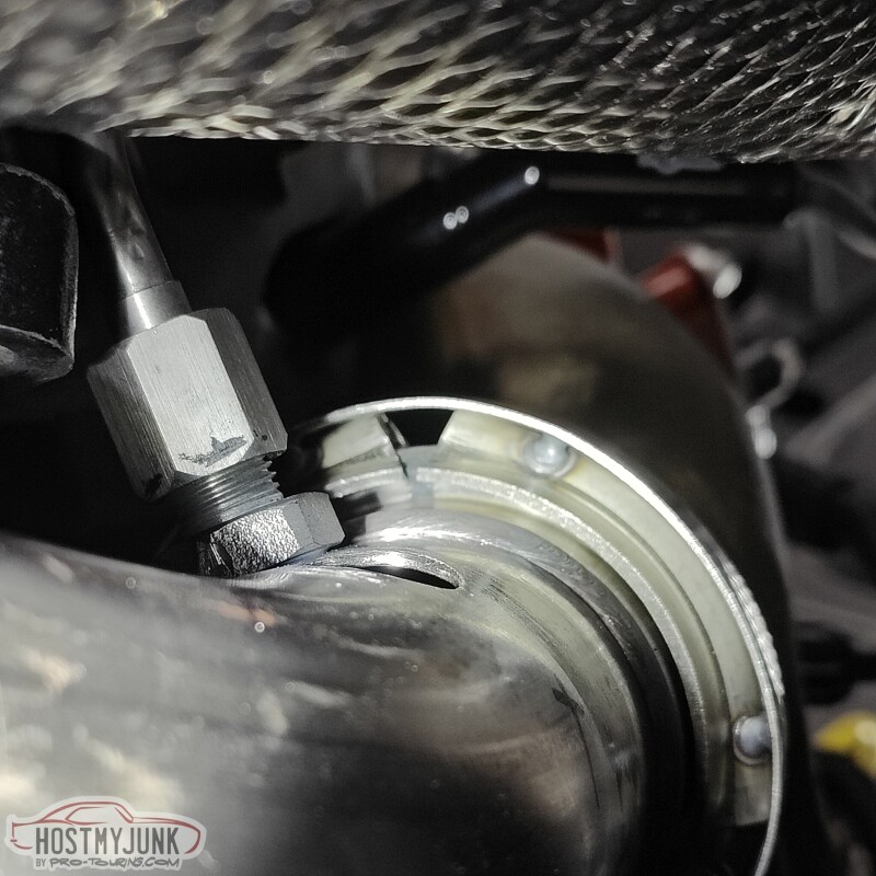
and the tube extends down to the crossover pipe...
Once the tube was the right length and clocked correctly, the sleeve was welded to the tube.
Andrew
This is what Ford uses for the exhaust pressure sensor, and I figured I can use it for the same purpose. In this picture, the tube has been cut and a sleeve installed over the cut. The sleeve ends where the green tape is and where my finger is pointing.
This is the sensor part number. From what I have been able to gather, it is a 0-54psi sensor.
The tube is stainless and 5/16" diameter and it uses 37 degree flares with tube sleeves and nuts at both ends. That size tubing translates to an -AN5, which is not super common. Luckily, I had this 90 degree NPT to -AN5 adapter that I was using on the old tank for the return line. The NPT side has been cut off and Vic turned it down in the lathe to make a -AN5 male weld fitting.
Here you can see where the fitting is going to go. Yes, the first hole was way off...
The whole assembly is bolted to one of the holes on the back of the heads...
and the tube extends down to the crossover pipe...
Once the tube was the right length and clocked correctly, the sleeve was welded to the tube.
Andrew
Thread Starter
Joined: Mar 2003
Posts: 10,617
Likes: 1,883
From: Little Austin
I arrived at Vic's this morning and found that he had already stuck the stock dipstick into the lathe and got rid of the ugly yellow dipstick handle.
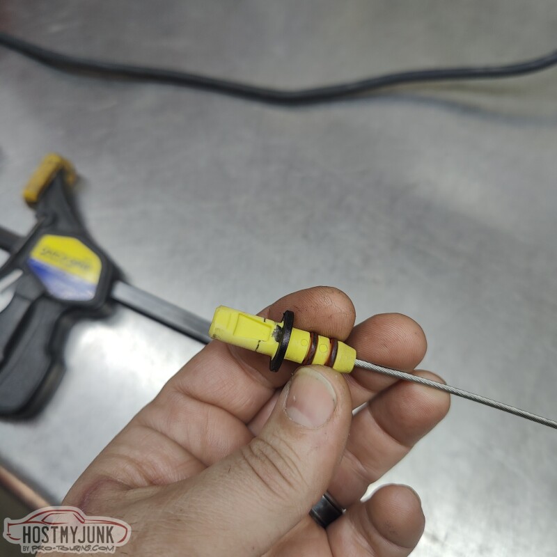
He also took a piece of Delrin that he had on hand and made a new new dipstick handle, which is much more appealing.

Once the parts were ready, they were cleaned and mated together with some JB Weld.
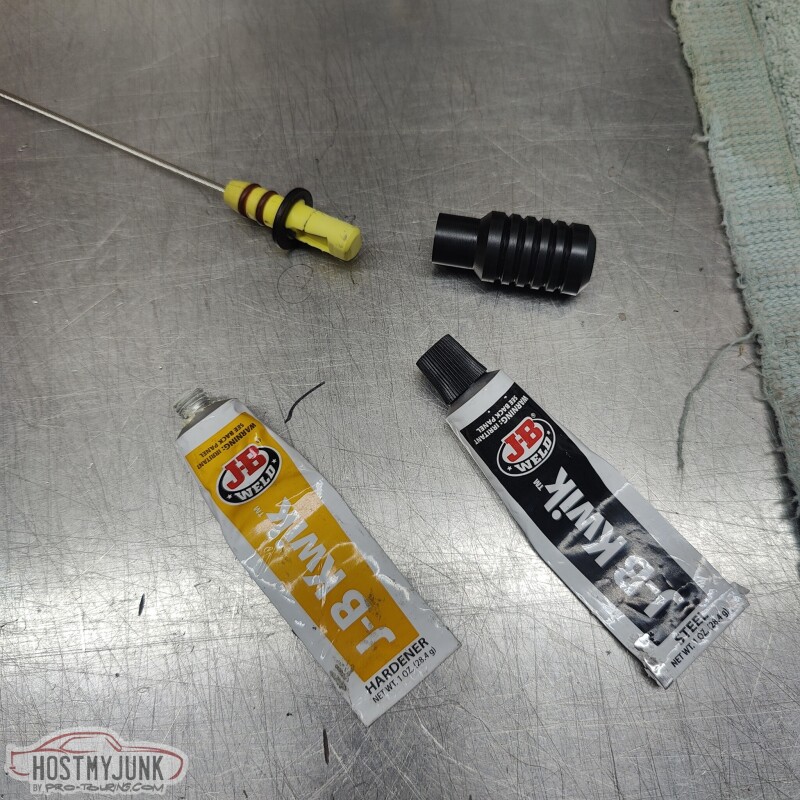
Much better...
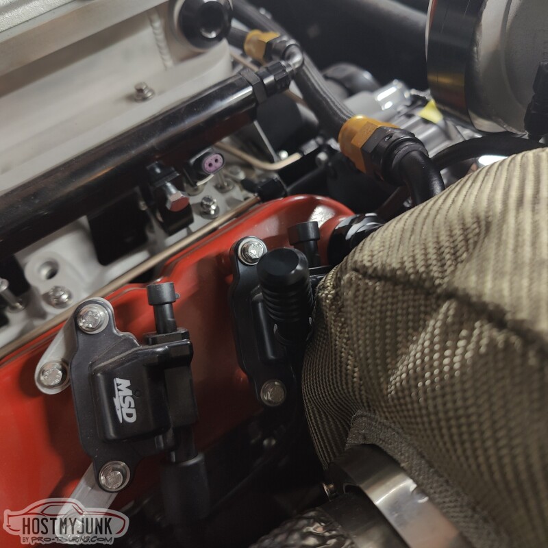
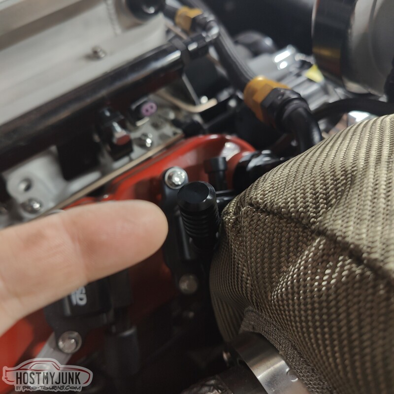
Here it is, in case you didn't notice it.
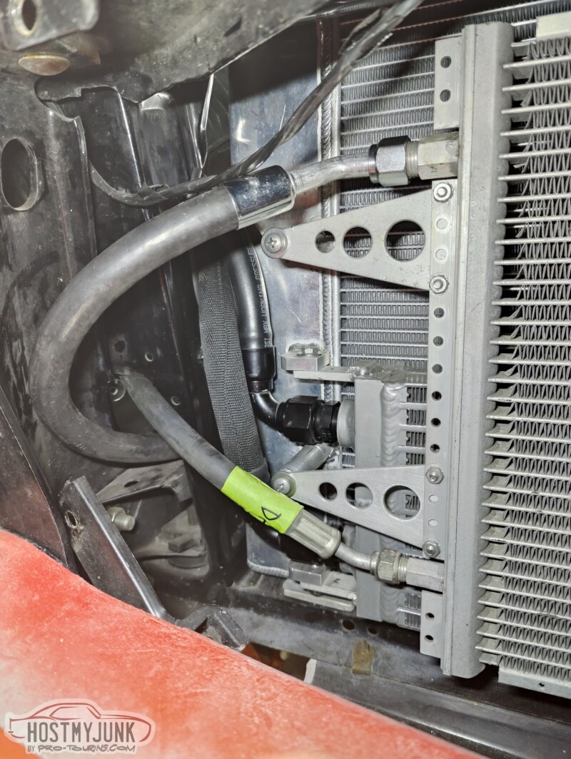
I also mounted the AC condenser in its location and removed the protective cardboard from the radiator.
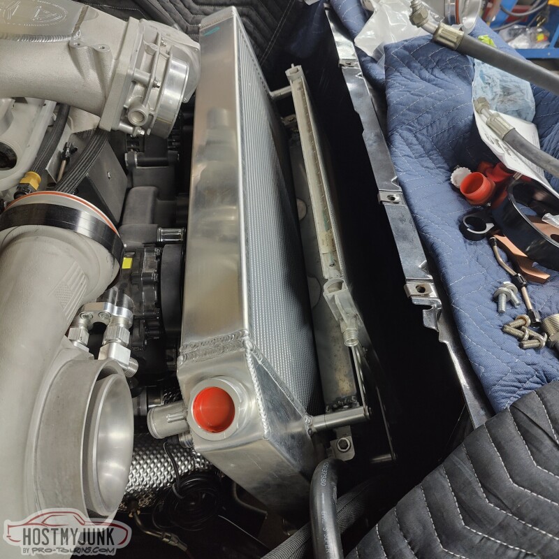
I will have the AC and the heater plumbing sorted pretty soon.
Andrew
He also took a piece of Delrin that he had on hand and made a new new dipstick handle, which is much more appealing.
Once the parts were ready, they were cleaned and mated together with some JB Weld.
Much better...
Here it is, in case you didn't notice it.
I also mounted the AC condenser in its location and removed the protective cardboard from the radiator.
I will have the AC and the heater plumbing sorted pretty soon.
Andrew
Thread Starter
Joined: Mar 2003
Posts: 10,617
Likes: 1,883
From: Little Austin
I decided that I wanted to rotate the Holley Lo-Ram front to back, which will put the MAP sensors in the front.
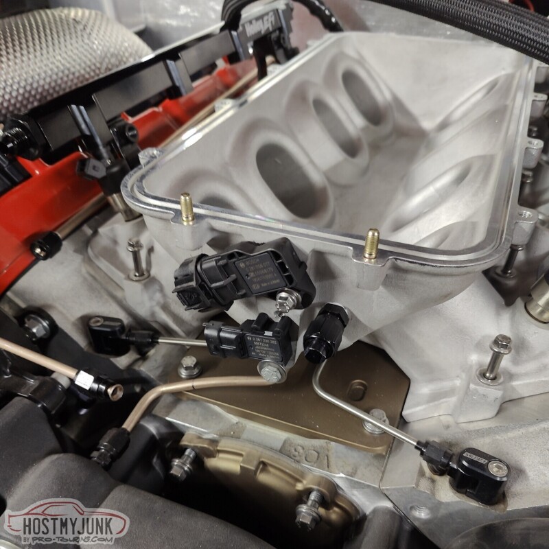
The main purpose for rotating the manifold is to clean up the area behind the intake and have the ability to use the stock oil pressure sensor in the stock location. I should have done this at the beginning...
Rotating the manifold involved a bunch of changes. One of them being the plate that holds the boost solenoids. It still fits, but it had to be cut to clear the Bosch TMAP sensor.
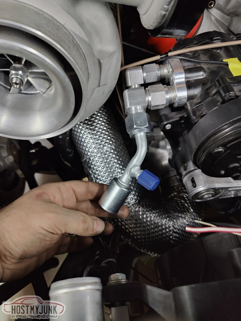
I also picked up some AC hose ends locally. The top hose that goes to the condenser is from the compressor.
The lower hose goes to the dryer. I have a new dryer on the way along with a AC pressure sensor, which will replace the binary switch. The AC compressor will be controlled by the Dominator ECU and the HardWire PDM.
I got a 45 degree fitting for the #10 hose that goes from the evaporator to the front port on the compressor. The rear port on the compressor is a #8, and goes to the top of the condenser.
I also took out the dash insert.
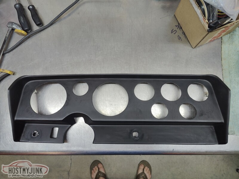
With the ash insert out, I will be able to get to all of the wiring and ducting behind the dash, without actually having to pull the dash out. The 3 gauges that are front and center will be the Holley CAN RPM and Speedo, as well as a small fuel level gauge.
The holes on the right will be filled in. The 6.86" Holley Pro-dash will go where the three larger gauges used to be and below that will be two AC vents.
Andrew
The main purpose for rotating the manifold is to clean up the area behind the intake and have the ability to use the stock oil pressure sensor in the stock location. I should have done this at the beginning...
Rotating the manifold involved a bunch of changes. One of them being the plate that holds the boost solenoids. It still fits, but it had to be cut to clear the Bosch TMAP sensor.
I also picked up some AC hose ends locally. The top hose that goes to the condenser is from the compressor.
The lower hose goes to the dryer. I have a new dryer on the way along with a AC pressure sensor, which will replace the binary switch. The AC compressor will be controlled by the Dominator ECU and the HardWire PDM.
I got a 45 degree fitting for the #10 hose that goes from the evaporator to the front port on the compressor. The rear port on the compressor is a #8, and goes to the top of the condenser.
I also took out the dash insert.
With the ash insert out, I will be able to get to all of the wiring and ducting behind the dash, without actually having to pull the dash out. The 3 gauges that are front and center will be the Holley CAN RPM and Speedo, as well as a small fuel level gauge.
The holes on the right will be filled in. The 6.86" Holley Pro-dash will go where the three larger gauges used to be and below that will be two AC vents.
Andrew
TECH Apprentice
Joined: Jan 2015
Posts: 313
Likes: 127
From: Austin area
I know you like the OEM stuff, but have you considered using a II MUCH filter instead of the OEM carbon canister?
The whole area behind the rear seat was covered with MLV. It was sad to have to cut into it...
But I needed access so that I could install this...
It is a OEM fuel vapor separator. I plan to vent the tank though this and then into a small charcoal canister. That should keep most of the fuel vapors at bay.
I sealed it against the body with some butyl rope.
Here you can see where the lines exit, just above the rear crossmember.
I also played around with the new gauges.
It is a little frustrating that the Holley gauges are 4" instead of 5", so something has to be done about that...The fuel lever gauge fit great into the 2 1/16" hole.
Andrew
Thread Starter
Joined: Mar 2003
Posts: 10,617
Likes: 1,883
From: Little Austin
Thread Starter
Joined: Mar 2003
Posts: 10,617
Likes: 1,883
From: Little Austin
This is a small update with, hopefully, useful information.
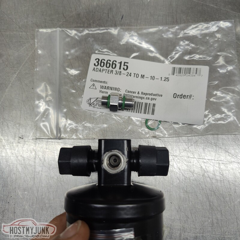
Since the Holley EFI will be controlling the AC compressor, I wanted to use an AC pressure sensor. This is a little adapter that VA sells just for that purpose. Also pictured is a new VA dryer, where the fitting goes.
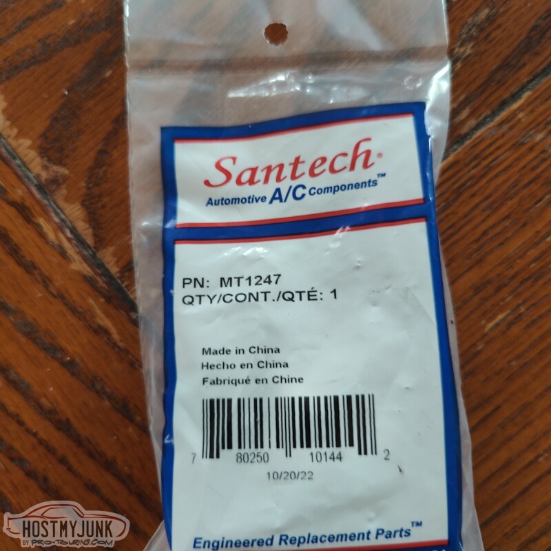
This is the AC pressure sensor that I am using. The main reason that I picked it is because I have the output configuration for it.
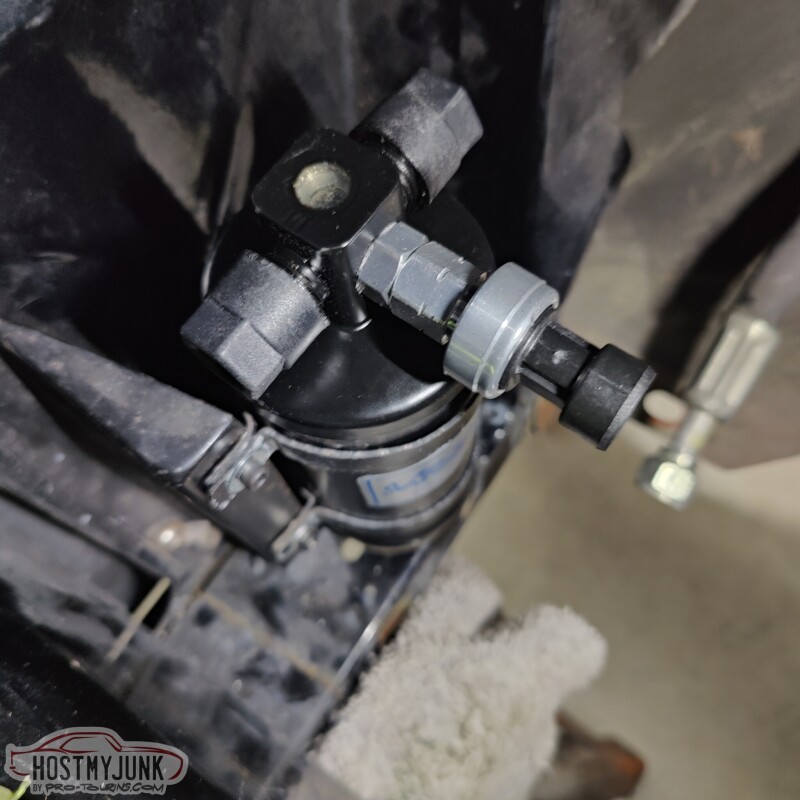
This is the new dryer, installed in its location on the radiator core support.
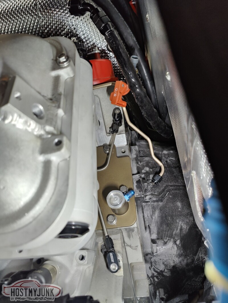
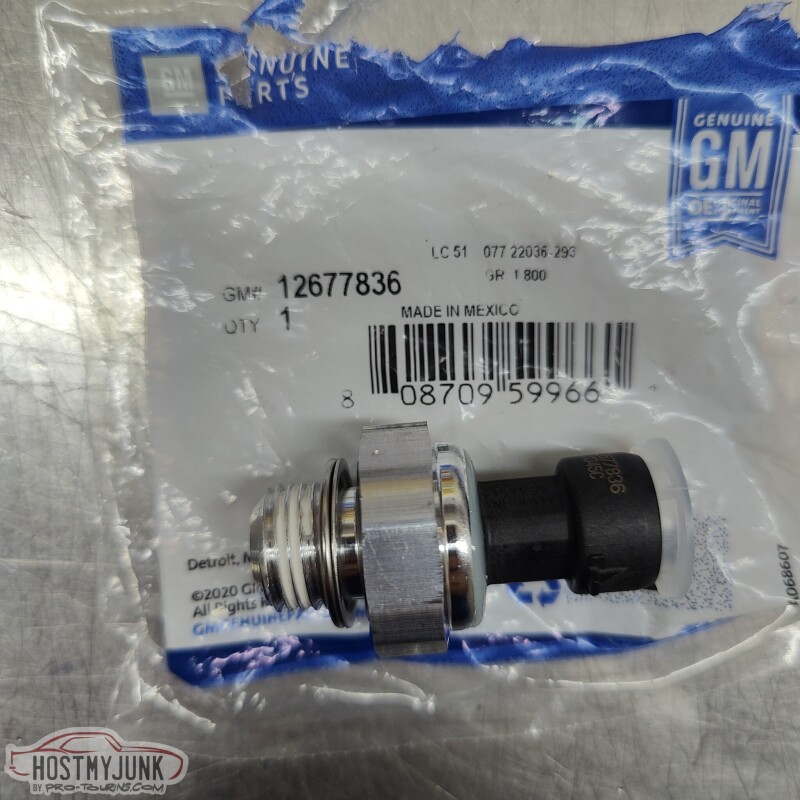
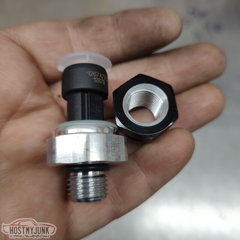
A lot of people ask me which oil pressure sensor I like to use on Gen 4 engines with Holley EFI. This is the one, and the connector on the Holley EFI harness has the correct connector. It is a 135psi sensor.
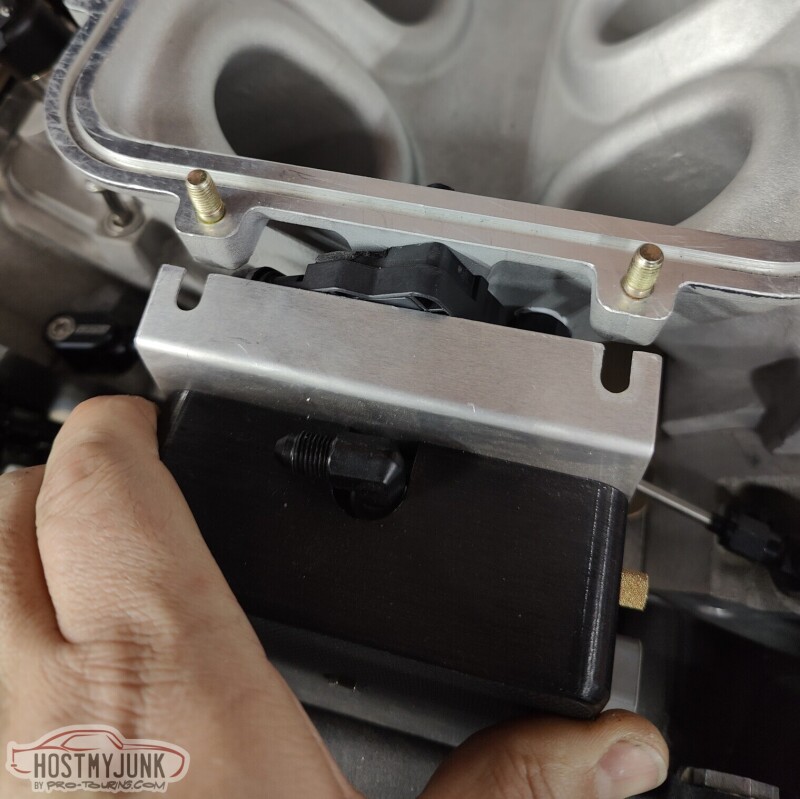
This sensor looks similar, but it has a 12mm thread on it, instead of the 16mm thread on the sensor shown above. I had this end cap for the Holley fuel rail, so I had an idea...
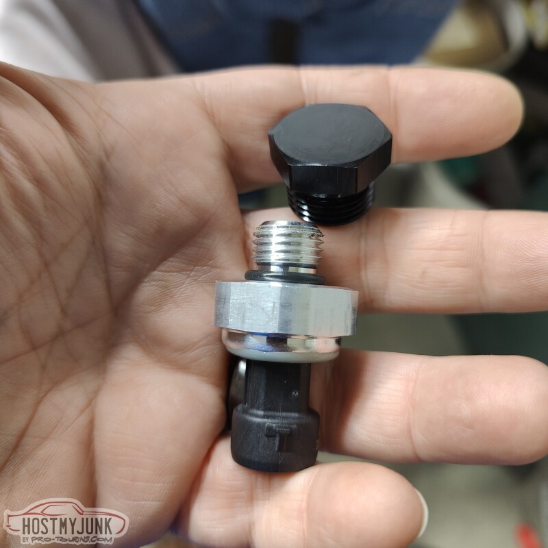
I told my idea to Vic and a little while later my idea was made reality.
Vic drilled and tapped the cap for the 12mm thread and a groove for the o-ring to seat against.
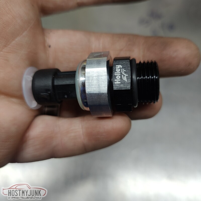
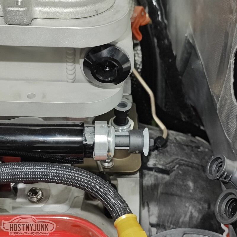
I installed it in the rear of the driver's side fuel rail. So I have a fuel pressure and temperature sensor after the fuel filter and this sensor in the rail, mostly because I can.
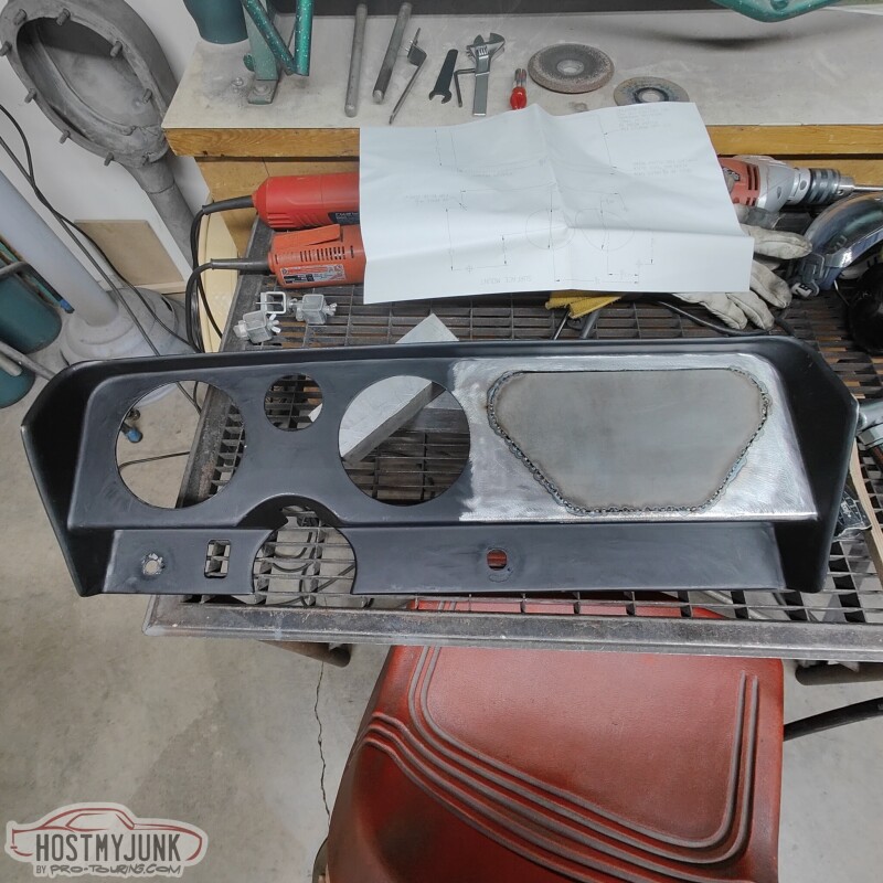
Vic is also making progress on modifying the dash insert to use with the Holley Pro-Dash.
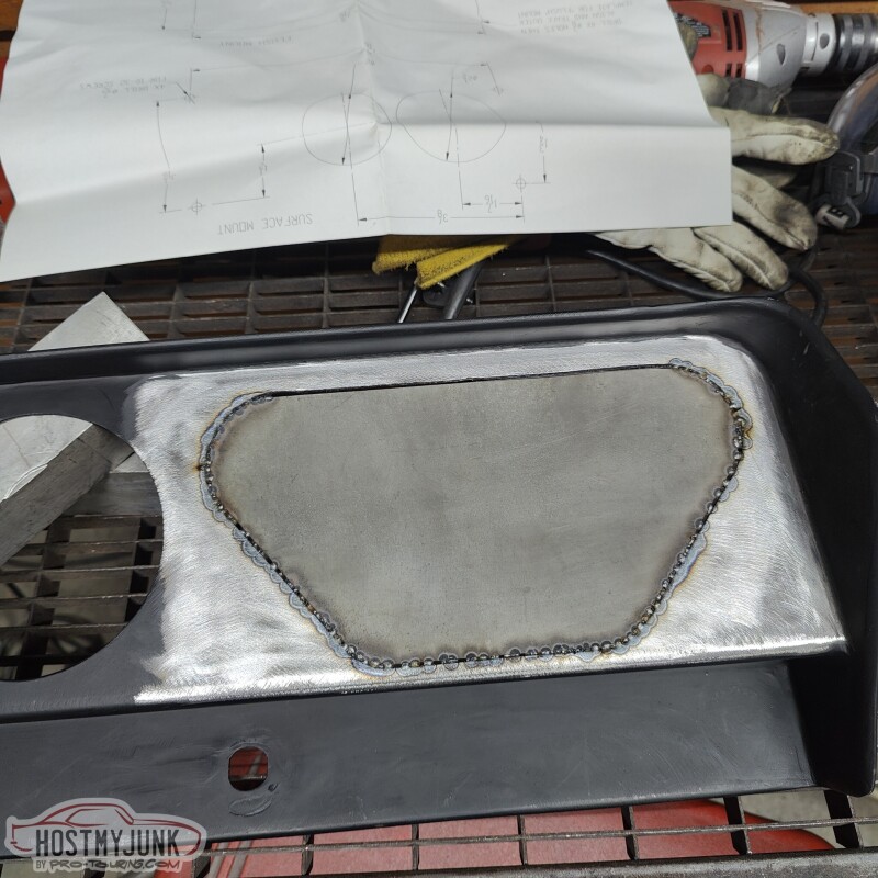
The small hole to the right of the steering column will also get filled.
Andrew
Since the Holley EFI will be controlling the AC compressor, I wanted to use an AC pressure sensor. This is a little adapter that VA sells just for that purpose. Also pictured is a new VA dryer, where the fitting goes.
This is the AC pressure sensor that I am using. The main reason that I picked it is because I have the output configuration for it.
This is the new dryer, installed in its location on the radiator core support.
A lot of people ask me which oil pressure sensor I like to use on Gen 4 engines with Holley EFI. This is the one, and the connector on the Holley EFI harness has the correct connector. It is a 135psi sensor.
This sensor looks similar, but it has a 12mm thread on it, instead of the 16mm thread on the sensor shown above. I had this end cap for the Holley fuel rail, so I had an idea...
I told my idea to Vic and a little while later my idea was made reality.
Vic drilled and tapped the cap for the 12mm thread and a groove for the o-ring to seat against.
I installed it in the rear of the driver's side fuel rail. So I have a fuel pressure and temperature sensor after the fuel filter and this sensor in the rail, mostly because I can.
Vic is also making progress on modifying the dash insert to use with the Holley Pro-Dash.
The small hole to the right of the steering column will also get filled.
Andrew