When you click on links to various merchants on this site and make a purchase, this can result in this site earning a commission. Affiliate programs and affiliations include, but are not limited to, the eBay Partner Network.
So I started to measure the "A" distance by placing a straight edge against the transmission side face of the bellhousing and using a dial caliper. All of the fingers have a slightly different height so I wasn't really sure what to do for measuring. I decided to do the hard, **** thing and measure each and every finger and then take an average. Trying to hold a straight edge against the bell face while holding a dial caliper in the other hand while trying to measure down to "rounded face" clutch fingers is a very frustrating thing to do. Extremely frustrating!
My brother-in-law is a construction guy who specializes in home improvement. He builds things. He once said, "I can do this in 2 hours. If Danny helps me, it'll take 8 hours!" I'm so embarrassed to admit that it took me hours to measure those fingers. Hours! Even then, I didn't trust the measurements because the one-person process was so frustrating. I just needed a third hand. My wife eventually came home and she helped me.
I tried another way of measuring. I placed a very large diameter washer over all of the fingers and measured the distance down to the washer. Of course I did the math to account for the washer. My wife also helped me with the "B" measurement. I had already removed the spring from the slave cylinder to be able to retract the bearing fully aft. It's amazing how much faster things can go when you have a little bit of help. I don't have any pictures of the actual measuring process because I was already out of hands even without trying to hold a camera.
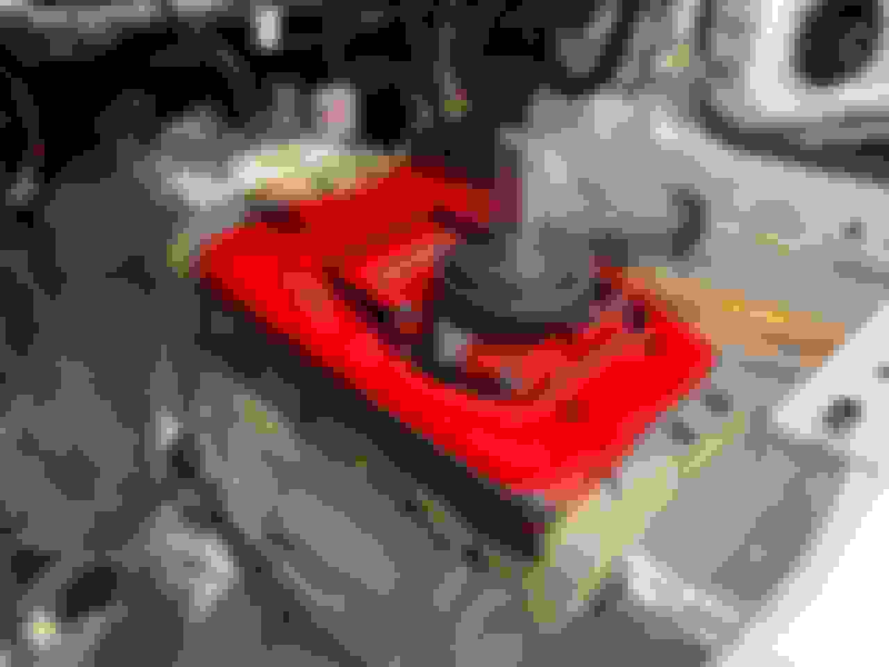
After the two methods of measuring, I came up with bearing to clutch finger gaps of .420" and.409". Way too much gap and it was time to buy the Tick Performance 3-pack of slave shims:
With my two methods of measurement, I came up with clutch finger to slave cylinder gaps of .420" and .409" meaning I was going to have to install a shim behind the slave cylinder on the transmission side to take up some of the excessive gap. The Tick Performance Slave Cylinder Shim Kit comes with three shims: 1. .180" thick 2. .113" thick 3. .055" thick
At the time, I never could find an actual recommended gap. It seems that different clutch companies have different recommendations. None recommended more than .250" and some recommended a gap as little as .125". Right or wrong, I decided to just use my Tick shim kit's thickest shim, .180".
.420"-.180"=.240"
.407"-.180"=.227"
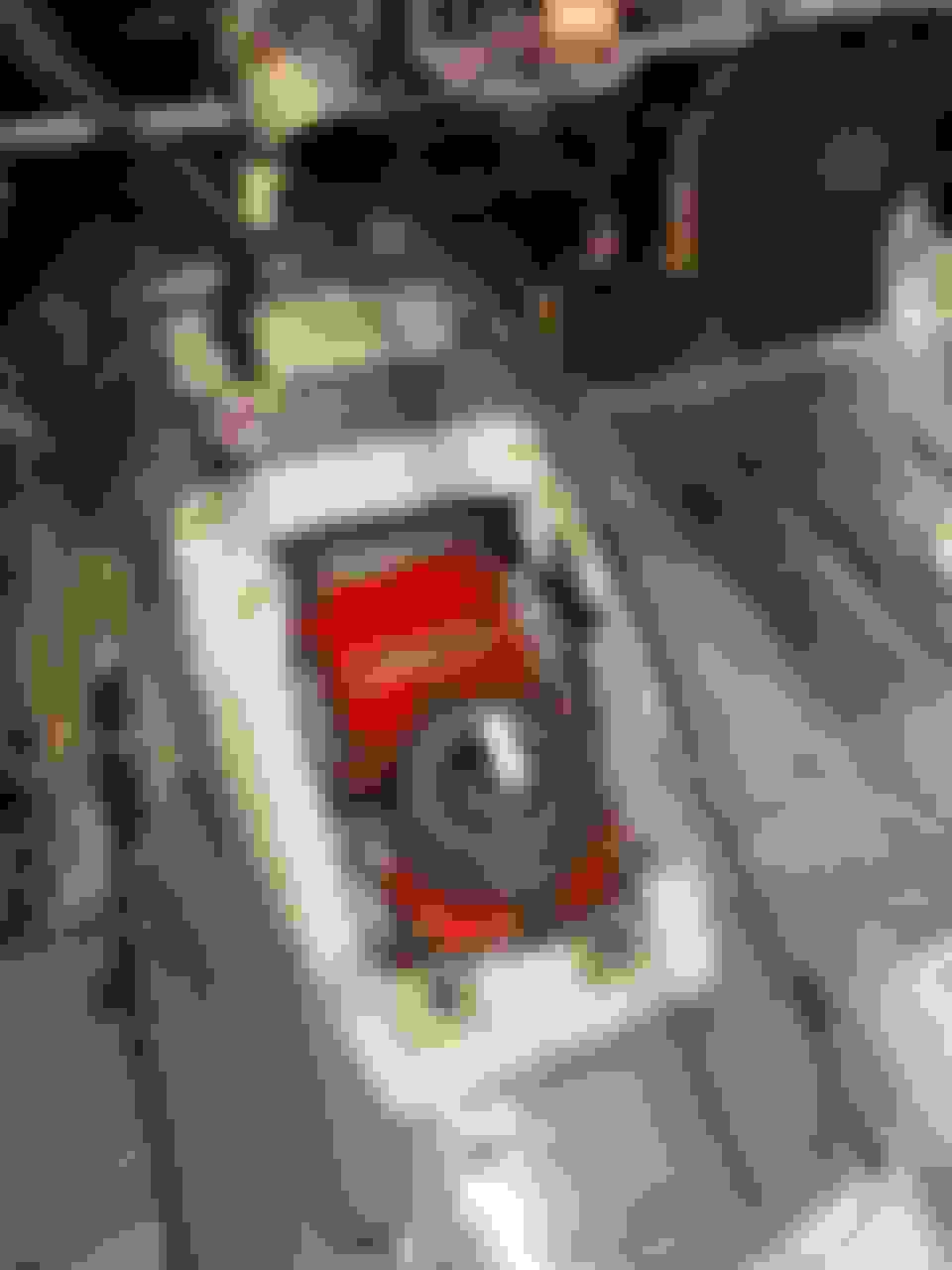
You can see the .180" thick shim between the slave cylinder and the transmission.
At the time, I was satisfied with those results but Andrew (Project GatTagO) has recently recommended that I use a tighter gap. In hindsight, I should've combined the .180" thick shim with the .055" shim. Andrew has recommended that I test my clutch system before too much more progress is made to make sure my gap isn't excessive. Just to let everyone know, as of this writing, the transmission is completely installed. There is no driveshaft, no exhaust system and nothing has any fluid in it. If I have to take things back apart, it'll suck but it won't be the end of the world.
Last edited by dannyual777; 02-17-2021 at 08:38 AM.
Reason: added picture
Back to the past timeline. So with the slave cylinder now shimmed, I turned my attention to measuring the alignment of my new, aluminum, OEM style Tremec bellhousing.
I don't think that most people align these OEM style, aluminum bells but I just knew that I'd get one that was out of tolerance and it would give me grief down the road. Plus, I just wanted to measure it to get the experience. Maybe in later years, I'll swap the aluminum bell for a Quick Time steel bellhousing. Those need to be checked for sure.
Once again, I did a lot of online research on how to check the alignment of a bellhousing. Most of the information and videos were aligning steel bellhousings. The process is the same.....well, almost! Here is a link to a nice bellhousing alignment procedure: Bowler Transmissions Bellhousing Alignment
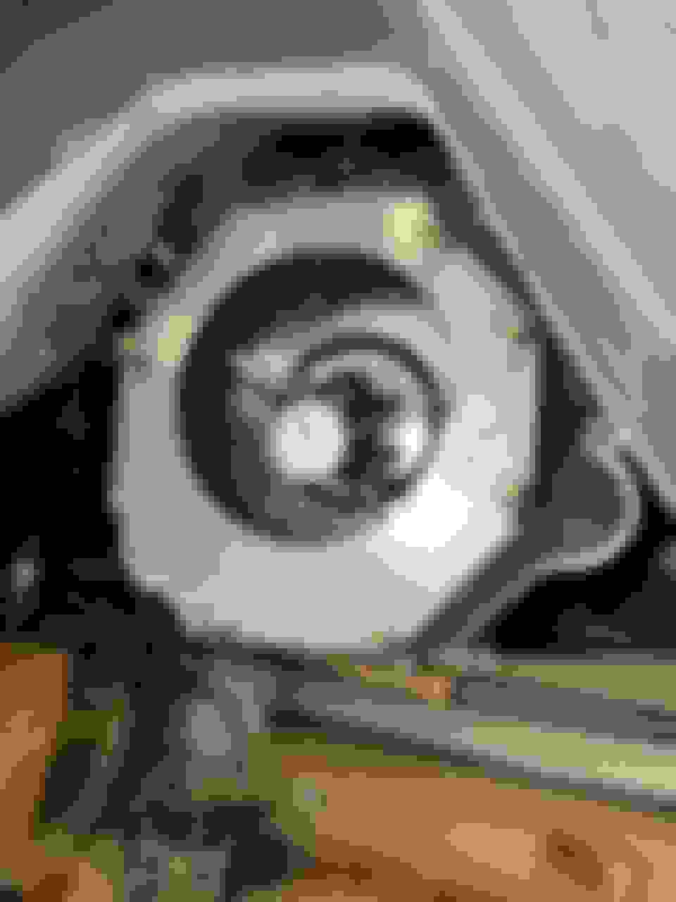
Ok. I'm now ready to get under my car and place my magnetic based dial indicator and I see this:
What the...???? Where is the perfectly round hole in the center of the bell?
Like I've already said, most videos and written writeups were all aligning either aftermarket steel bellhousing or old school sbc and bbc OEM aluminum bells for Muncie and Borg Warner 4-speed transmissions. Those bells have a nice round hole in the center of the backside (transmission side) of the bell for your magnetic base dial indicator to ride on.
I felt stupid and angry at the same time. How could I have not noticed that my Tremec bell didn't have a round hole in the back and how come I never saw a video with someone trying to align one??? Yeah, I wasn't happy at all !
To me, the much larger diameter hole in the Bowler plate would make getting my magnetic based dial indicator situated much easier. It also seemed to me that there would be less chance of error with that much larger diameter hole. Add in the fact that it was a little less expensive and I ordered one up from Bowler.
Once my Bowler dial indicator plate arrived, I bolted it up to the back of my Tremec bellhousing and mounted my magnetic dial indicator. I don't have any pictures of the first measurements so I'll have to cheat and show you this picture from about 10 days later.
The number showing on the dial indicator doesn't match up with what is written on the plate because this picture was taken about 10 days later when my offset dowel pins arrived. I installed them in the wrong direction and got the terrible number shown on the dial indicator.
When I took my first measurements, my bellhousing's alignment showed off by .019" right up in the one o'clock position where the piece of masking tape is in the picture. I know I have .017 and .018 written with a Sharpie but the actual number was .019" total indicator reading. This meant that I needed an offset dowel of .007". Why? Because you double the .007" and that equals .014". That offset dowel will now make the reading .005" (.019"-.014"=.005") I ordered a pair of offset dowels from RobbMc
The dowels arrived and the first thing I noticed about them was that they were long. Way too long! Great. Now I've got to call RobbMc. I tell them my dowels are too long and they ask me if I read the instructions. I said, "I've got the instructions right in front of me!" He asks, "did you read the first paragraph?" The first paragraph states very clearly in black and white:
IMPORTANT: RobbMc offset dowels are longer than stock dowels. In some cases this means that the portion of the dowels that extends from the engine block must be shortened. The dowels are not hardened so they can be cut off with a hack saw Be sure to deburr and chamfer the dowels after shortening.
Boy did I feel like a moron. He told me that some guys use an engine plate between the block and the bellhousing and that is why the dowels are extra long. I apologized for wasting his time!
The dowels were very easy to cut even with my old, dull hacksaw blade.
Cleaned up and ready to offset .014" of my .019" misalignment.
I now needed to get both shortened dowels installed at the correct angle to offset the misalignment. I've got this nifty, magnetic, digital angle finder. I love this thing and it is very accurate and repeatable. Since I've got this thing, I decided to get extra **** and start measuring the actual angle of where my misalignment was.
Yes. I used a standard protractor to find the angle. The protractor is not in the proper position for measuring in this picture. I just took this picture to show the items that I used to get a close angle measurement. Probably way too **** but why not?
Confirming that the engine is completely horizontal with my digital angle finder. Great tool to have and it's come in very handy time and time again in this build. ***Pretend*** that there is no pencil mark on the dowel hole above the angle finder. This picture was taken out of order.
That's about the angle that I'm looking for.
Angle marked so I can get one of my RobbMc offset dowels oriented properly. I marked the other dowel hole on the driver's side of the engine as well.
I get under the car and slide both of the shortened, offset dowels pointing in the direction that I marked. Having never done this, I had a 50-50 chance of getting them in the correct direction. I pretty much always lose 50-50 situations and this time was no different . I already posted this picture in a previous post but here it is again. My numbers got much worse so I knew that I had placed the dowels 180 degrees out from the proper way they should've been placed.
Now my alignment is off even worse that when I started. My offset dowels are offset in the wrong direction.
I take everything back apart and quickly turn both offset dowels 180 degrees. I put it all back together and measure again. Here is what I ended up with:
Success!!!! Look at that! Total indicator reading of .004". I'm well within the standard .010" specification and actually within Bowler's high performance, 7500+rpm shifting specification!
I was very happy and I took everything apart and went to tighten the Allen bolts inside the RobbMc dowels to lock them in place. The instructions say to not gorilla those bolts in so I used a hand held Allen wrench and tightened the passenger side. Nice and snug. Now, on to the driver's side. I kept turning the Allen wrench but the bolt never would get tight. It eventually bottomed out in the hole and the dowel was loose in the hole. Nooooooooooooo !
I called RobbMc and after some discussion, they told me to send the bad dowel back to me. It took about a week before I received the replacement from them. I had to cut it down and clean up the cut area. I did notice that it seemed harder to see the .007" offset than the original dowels. I had a much harder time finding the offset on this dowel. Whatever. Time to install it.
I mounted up the bellhousing, Bowler alignment plate and my magnetic base dial indicator. This time, my measurements wouldn't come closer than .006" TIR. Still well within the .010" recommended specification but just outside of the .005" "high performance, 7500+rpm shifting" specification. Hmm. I wonder if the replacement dowel wasn't quite .007" offset .
At this point, I decided to call it a day and know that I'm well within the .010" spec. The Allen bolt inside the replacement dowel hand tightened up just perfectly as the passenger side dowel had done a week or so earlier.
This is a nice picture showing the Bowler dial indicator alignment plate. It's steel, not aluminum. I highly recommend it.
I bought this Harbor Freight transmission jack because I was tired of trying to use floor jacks. I found a 20% off coupon and made the purchase. It's a nice jack and so far it's been worth every penny. I love the way the jack's handle can swing around 360 degrees. The wooden cradle under the transmission is something that I built about 10 yrs ago when I had to use a floor jack to remove my Trans Am's T56 when the slave cylinder gave up the ghost. The cradle works very well but it adds height to everything.
With the transmission jack, stabbing a Tremec T56 Magnum becomes a one-person job! A helper is always better but when you're a "do-it-alone" worker like myself, the transmission jack was worth it's weight in gold!
Last edited by dannyual777; 02-20-2021 at 09:11 AM.
Reason: added text
The following work is out of chronological order. I apologize for not having posted this work prior to the work showing the bellhousing alignment. The postings to follow are of work before the bellhousing alignment!
I needed to try to get the T56 up into place in the transmission tunnel to eventually install the Hooker transmission crossmember. I bolted up the transmission without the clutch assembly installed because this was just to fit the transmission in place. The instructions for the Holley swap parts said that some "hammer clearancing" would be required. I wanted to find the hammer clearancing area(s). With a jack, I raised the transmission as high as I could and tried to get that Hooker transmission crossmember under the T56's mounting pad. Hooker's instructions say that you must use a pair of included spacers. There was no way I was able to raise that T56 anywhere close to where it needed to be.
The whole Tremec shifter assembly was contacting the coupe's transmission tunnel. I did some online research and found that the tunnels on auto transmission cars were modified for more height. The coupe was a former automatic car.
At this point, I was wondering if something was wrong with my car. This situation was way beyond "hammer clearancing!" I got online and started asking questions. People responded and I found out that all of these 1987-1993 Fox body cars had the same transmission tunnel. However, the manual transmission cars' tunnels were modified on the assembly line and a tunnel hump was added for more height so the trans could be up higher. I read that this modification was done by hand on the Ford assembly line and if one were to look carefully under their OEM manual transmission car, they'd see the signs of hand modifications.
Here's a picture of the underside of the transmission tunnel of my donor car, the 1991 Mustang GT:
Those cuts definitely look like they were done by hand.
Coming back to the topside of the transmission tunnel in the donor car we see this:
Now it's clear! Yes, there is an additional hump installed over the transmission tunnel. Compare this picture to the first picture in this post.
Now it was making sense. I needed a "manual transmission tunnel hump." Some quick online research showed that aftermarket transmission tunnel humps were available for about $100. In hindsight, I probably should've purchased one but sometimes I make decisions that sound good at the time but later prove to be way too much work !
Because of the sentimental notion, I thought that it would be good to remove the tunnel hump and install it on the coupe. My wife thought it was a good sentimental idea as well. Little did I know how much work it was going to be.
The factory had spot welded the manual transmission tunnel hump onto the larger cutout that was done on the assembly line. I ended up using large drill bits to drill out those spot welds. I know that there are spot weld cutter bits available but I don't own one. I probably should just buy one and have it in my toolbox. Anyway, it was a ton of work drilling out all of those spot welds. There were a lot of them and I had to drill really big holes; much larger holes than I would've guessed.
Here are some of the first drilled out spot welds. Actually, they're not quite drilled out. I needed to use a much larger drill bit to cut out all of the weld.
I needed to cut the coupe's transmission tunnel sheetmetal out larger to get the T56 up higher where it needed to be. I had to start somewhere and it ended up being a lot of trial and error. Here are some pictures of the beginning:
I used a large pair of very good tin snips to cut the sheetmetal. I probably should've used a cutoff wheel in my pneumatic die grinder but metal particles would've flown everywhere.
The hole is getting close to how it needs to be shaped. Not quite there, yet.
After way too much work, I finally got the transmission tunnel hump off of the donor car. Look at all of those big holes I had to drill. I'm just getting an idea of where the hump needs to be placed and what kind of clearance issues I have with it and the Tremec shifter.
It took multiple tries of raising the transmission as high as I could, seeing where the trans/shifter was contacting the car, cutting and then repeating the process until I felt that I had the transmission where it should reside. I remember discussing the T56 Magnum's fit with Toddoky, the Holley engineer, and he had said that there are protrusions on the side of the trans case that may need to be cut off due to interference with the tunnel. Yep. I had to do that.
In the foreground of the picture are two of the protrusions. Back toward the bolt, you can see an already cut protrusion.
Here is another picture of the passenger side. You can see that I've already cut off one protrusion right by the black rubber plug. Yes, I had to cut the other one off up higher that's contacting the body of the car.
Thankfully the aluminum was very easy to cut even with my dull, worn out, 10 year old hacksaw blade. I need to remember to buy new hacksaw blades!
Looking good! Nice to see someone actually paying attention to the details. Did you also turn the dial indicator to check if the flywheel mating surface was parallel to the face of the transmission (bell mounting surface)?
I don't know if I just got lucky or if Quicktime knows their sh$t. The worst reading I had -- both for concentricity and parallel was .001". Taking measurements 90 degrees apart (actually you turn the motor over so you can see the dial sweep across the entire 360 degrees) - I had .000" on two of the axis and .001" on the other two. Same on parallel readings. I took it all apart and put it back together and measured again - same thing. Lucky, lucky, lucky.
Michael, I was so frustrated after taking the slave cylinder to pressure plate finger measurement and bellhousing alignment numbers that I just plain didn't want to know. I'll admit that I was POd and I told my wife that if I measured the flywheel surface, like the Bowler Transmisssions instructions recommend, that I'd have even more stuff to deal with so I decided to just bury my head in the sand. I know that I should've done it but I didn't.
After raising and lowering the transmission numerous times, I finally had the shape of the shifter hole that I needed to clear everything. I cleaned up the rough edges with files and then applied some paint with a brush to the edge.
Final shape of the Tremec shifter hole.
Painted the cleaned up, cut edge to keep it from rusting.
Believe me - I understand. I used an aluminum flywheel. So I had to make a steel plate that bolted into the center of the flywheel with a couple of the flywheel bolts so I'd have something for the magnetic base to stick to. I'm like - you gotta be kidding me. But I'm glad I did it. Peace of mind that everything related to alignment was gonna be ok.
Michael, I'm probably going to have to remove the transmission again because the gap between my slave cylinder and pressure plate fingers is probably too big. Andrew suggested that the current gap of .227"-.240" (post #181) is too large by about .050". I only used the thick, .180" Tick shim. I should've used the thin, .055" shim as well.
If I have to take things back apart, I might as well measure the flywheel run-out at the same time.
If I had to do it all over again, I would've purchased a new, aftermarket transmission hump. It was way too much work to remove the hump from my donor car and the large holes drilled are certainly not ideal.
I applied urethane sealer between the trans tunnel and the hump and then I used stainless steel rivets to connect everything. It worked great. The Home Depot purchased urethane sealer is just like automotive body seam sealer just a whole lot less expensive. It came highly recommended when I did some online research. FWIW, it even looks to be about the color of the OEM Ford body sealer.
Look at all the rubber plugs I put into the large holes that I had to drill. It looks really bad but I knew that it would all be covered up anyway. I left it red for sentimental reasons.
You can see the urethane "body sealer" squeezed out from between the transmission tunnel sheetmetal and the hump. Everything is well sealed and very solid! If you look to the far right of the picture, you can see the similar color of the 30 year old, OEM body sealer.
About $7 for this tube at HD. Beige color. It was easy to apply with a caulk gun and now I have plenty left over for other areas of the car project if needed.


 02-16-2021, 08:40 AM


 !
!


 . I already posted this picture in a previous post but here it is again. My numbers got much worse so I knew that I had placed the dowels 180 degrees out from the proper way they should've been placed.


 .
.


 !
!