When you click on links to various merchants on this site and make a purchase, this can result in this site earning a commission. Affiliate programs and affiliations include, but are not limited to, the eBay Partner Network.
I have 220V in my garage because of my 4-post Whip Industries lift so I went with the dual voltage machine. Other smaller Hobart welders would have suited my needs but I wanted more welding options for the future.
I got a 10% discount from Tractor Supply Company on the welder. I purchased the brand new welding gas bottle (filled with AR/CO2) locally for a very good price. Renting a bottle is just not my MO.
Simple with no digital readouts or anything like that. I'm not saying digital is bad, I'm just saying that this is a no frills machine.
Remember how much I dislike china made products? Lots of chinese wire out there but I found this 10 pound spool on Amazon for less money than buying china wire locally at TSC. It would be a lot of wire for me to practice with and to weld in my SFCs.
The only thing to do at this time was fire up the Hobart and start welding. I used an auto-darkening helmet (china made but a lot of very good reviews.) Not having any experience with welding, I found myself constantly touching the welding gun trigger when I didn't mean to and the wire would feed out. This kept happening again and again.
How do you like my "welding table?" It was the best that I had. I didn't have a clue as to how much sparks would be flying so I went ahead and put a piece of plywood on the rear of the donor car.
My first beads weren't too bad.
Here is my first try with welding two pieces of metal together. Not all that bad.
Lots of beads. Some better than others. Remember, I'd never welded prior to this.
I practiced welding off and on over the course of about 10 days. I had some scrap metal that was thinner than the metal in the previous pictures. I thought that practicing with that would also help me in that the Foxbody "frame" isn't very thick metal. I was pretty pleased with my practice beads and I now felt that it was finally time to weld in the subframe connectors.
I'd purchased Maximum Motorsports full length SFC that were powder coated black. Great looking SFCs but you do have to remove the coating everywhere you plan to weld. I had fitted up the SFCs under the car numerous times to get them in the proper position for the best possible fit and the smallest gaps. I used a Sharpie to make marks so I knew where to place each SFC when it was finally time to weld. I also marked everywhere that I needed to grind off the powder coating on the SFCs as well as the "frame" area of the car itself.
I tried using everything that I had in my garage and nothing removed that coating very well. I actually spun my wheels for about 2 hours on the first SFC trying to use carbide bits in my cordless drill. Waste of time. At the very least, I should've chucked the bits up in my pneumatic die grinder. I tried a grinding wheel on my 4 1/2 grinder. I tried wire wheels/cups on the grinder. I tried sandpaper. None of it worked very well and I was wishing that I'd purchased uncoated SFCs.
I knew that the best thing to remove the coating was to use a "flapper wheel" on the grinder so I ordered these:
Once they arrived and I used one, I couldn't believe that I'd wasted all of my time trying to use other types of abrasives. The flap discs worked like magic and I was very quickly able to remove the powdercoating from everywhere that I needed to weld. It worked just as well for removing the factory coating on the car although it was tougher trying to get the grinder in position under the car for it to do it's work. Still, the discs quickly removed any coating anywhere the discs touched. Magic!
I then got the SFCs back under the car and into position. I knew that grounding the welder is super important so one YouTube video welding pro suggested using a piece of bare welding cable or battery cable under the actual welder's grounding clamp. He said that this allowed all of the many copper strands to touch the metal in many places assuring a good ground. I'm a rookie so what do I know about welding? I'm going to try it.
The grounding clamp wouldn't open wide enough to fit the SFC but I used a C clamp and a piece of bare welding cable to connect the grounding clamp to the SFC. It was very easy to put the bare spot on the red welding cable on any bare metal spot of the SFC for a good ground.
So, I finally got to where my confidence in my welding abilities allowed me to finally weld in those SFCs. I had high hopes but the first time that I squeezed the welding gun's trigger on one of the SFCs, I knew things weren't going to be good. What I didn't realize is that when I was standing up beside my makeshift welding table during practice, I was at a perfect body position. I would get nice and comfortable before I started and usually everything went well.
Under the car on the wooden jackstands was a completely different story. I was contorted up into a pretzel and I just couldn't ever get in any comfortable position. I couldn't get the welding gun properly placed, the gun's angle was wrong and the gun's distance from the work surface was wrong. My welds at first weren't straight and there were times that I actually welded an inch or so past where my weld bead should've stopped. The welds were SO ugly! Beyond ugly. Heinous! They looked like I had never practiced welding and the first try was on the SFCs. I was so mad. To make matters worse, the SFCs are thicker metal than most of the Mustang's frame so I was occasionally burning holes in the thin frame. I'm a beginner welder and it was tough dealing with and fixing those holes. The rear frame seemed to be thicker than the front. I don't know how long it took me to weld in the passenger side SFC but it was a long time and very stressful.
I needed a break from the frustration and decided to give it a rest and do the driver's side SFC on another day. I knew that the driver's side was going to give me bigger problems in that the coupe's front frame was bent up from the previous owner putting a jack under there. There were bigger gaps and I knew that at my skill level, I was going to have trouble.
By the time I welded in the driver's side, my skills welding under the car hadn't improved. Heinous, heinous, heinous! The only consolation was that I was used to it by now. At the conclusion of the horrid welding session, I had to weld on the small reinforcing plate that Maximum Motorsports includes and says that you 100% must weld it over a "bend point." I'd already welded the passenger side plate in previously. I tried to get smarter than the Hobart welder's settings chart and I changed the settings. The weld around that plate was so bad that a 9 yr old kid could've done better. I actually had weld bead hanging down that resembled stalactites hanging down in a cave!
I was glad that I was finished with welding in the SFCs but I was anything but happy about it. Total frustration. If you think that I'm going to post pictures of the welding abortion, you're mistaken! I didn't even take any pictures of the welds because I was to angry and embarrassed and never wanted there to be any evidence that I did such poor and ugly work .
I told my wife that I was going to have to clean up all of the welds with a die grinder and carbide bits. I was worried that with my ugly beads and sometimes beads on top of beads, that I had porosity and voids. I also knew that grinding all of the welds was going to result in metal shards flying everywhere and I'd never get them out of my garage. I knew I had to let my car down off of the wooden jackstands, roll it outside and raise the car back up onto the jackstands. It's a lot of work because of how high the car is off the ground, it takes two "stages" of jacking up the car on each end. Jack it up part way, put blocks of wood under the tires, let the jack down, put long, wide boards under the jack and raise the car further off the ground.
My $95 assortment of USA made carbide cutter bits cut well and metal shards were everywhere. The bits cut so good that I was done within about 2 1/2 hours. I also used my angle grinder with flapper discs here and there where I could fit it. There was finally good news after all of the grinding. I found no porosity and no voids. There appeared to be good penetration. I did find one small burn through hole in the driver's front side that I hadn't seen. The ground welds were now just ugly instead of heinous! Believe it or not, there was one weld that I didn't grind at all. I think it was the passenger side, front, inside section.
I lowered the car, pushed it back into the garage and proceeded to sweep up all of the metal on my driveway. Lots of metal! I raised the car back up onto the wooden jackstands.
I knew that I had to paint those ground welds or they would rust.
I'm not sure why I thought brushing on some Chassis Shield was a good idea. It didn't brush on very well. I ended up spraying satin black, automotive trim paint. I tried to block off the spray area with small pieces of cardboard because I didn't want over-spray everywhere. The cardboard worked well and there was minimal over-spray.
After having thought about it for a while, I determined that since I'd posted the written story of what happened that the very least that I could do was to take the pictures of the ground and dressed welds and post them. I took these pictures a couple of days ago and here they are:
Passenger side, front, outside.
Passenger side, middle, outside To the lower left of the Maximum Motorsports welded on tab, you can see part of the ground down weld of the reinforcing plate.
Passenger side, rear, inside. This weld ground out nice and smooth.
No! These welds are not pretty and I'm not proud of them at all.
The next picture is of the only SFC weld that I didn't grind:
I thought it looked just ugly instead of heinous so I left it alone.
Here are some pictures of the welded in driver's side SFC:
Front, inside. This was a very difficult weld as there was a gap here due to the bent up "frame" from the previous owner improperly jacking up the car. I also burned through that thin frame at least once here, IIRC.
Rear, inside.
Middle, outside. Again, you can see the reinforcing plate weld to the lower right of the MM welded on tab.
Outside, front. Another difficult weld with at least one burn through hole that I had to fix. In fact, you can see a spot of bare weld where I recently found a hole.
No! There are no pictures of pre-dressed welds with the exception of the one that I posted first in this post. I'm not particularly happy about any of these welds but I am happy that its all done and now behind me!
Eh not too bad . They look to be on there solid and the car didnt burn down lol so Job well done. Smart to cover the weld with the catalysted paint tpo.
Eh not too bad . They look to be on there solid and the car didnt burn down lol so Job well done. Smart to cover the weld with the catalysted paint tpo.
Yeah. The welds do seem to be solid and I should count my blessings that the car didn't burn down! I did have a fire extinguisher placed nearby just in case!
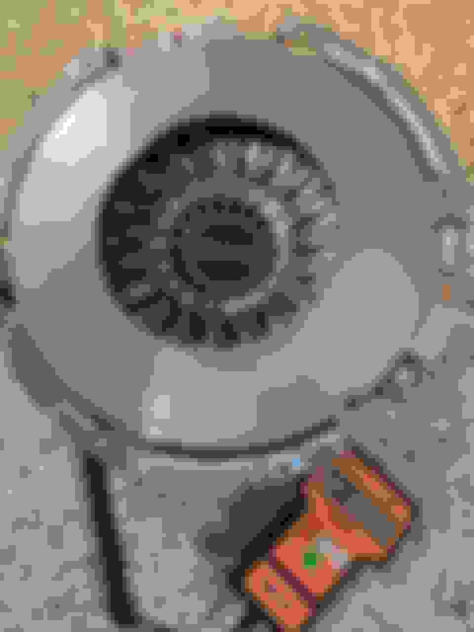
After the SFCs were finally in, it was time to deal with the clutch and transmission. I know everyone has their favorite clutch and there are a lot of choices out there. In the end I went with a Centerforce Dual Friction clutch. Why? Because I have one in my 406sbc, 1980 Z28 with a Richmond 6 speed. The car has been off the road since 2006 but I drove it with the CF Dual Friction clutch for 10 years with not a single clutch problem. No chattering, smooth engagement and no funny noise from the weights. Of course with the 3" exhaust, the car was pretty loud and I doubt that I would've heard any noise that some people claim those weights make. With my engine's current power, I think that this clutch will be just fine.
The kit even came with ARP flywheel and pressure plate bolts. It also came with different pilot bearing to fit different crankshafts. It was a very complete clutch and flywheel kit.
Last edited by dannyual777; 02-13-2021 at 09:03 PM.
Now it was time to start doing some clutch measurements. There is a lot of discussion on the internet about whether or not you should measure the amount of slave cylinder to pressure plate gap as well as bellhousing/crankshaft centerline runout. Some guys will just install it all and cross their fingers and hope to get lucky. I've already been through a little of this about 9 yrs ago when the slave cylinder abruptly let go in my 2002 WS6 Trans Am.
I replaced both the slave cylinder and the clutch master cylinder with parts from Autozone. According to researched internet information, these "AP" (I think those are the markings) marked parts were what GM installed when the cars were built. After installing the new parts and bleeding the clutch, my clutch engaged and disengaged right above the floor. Not anything like stock. It was so bad that every time I switched cars between the Trans Am and the 5-speed donor car (1991 Mustang GT) it felt like I had to learn how to drive a standard transmission car all over again . The TA was no fun to drive with that weird to me, "right off the floor" clutch engagement and disengagement. I bled and rebled the clutch trying to make it better but there was no air in the hydraulics and that wasn't the problem.
After about a year of putting up with the situation, I decided to do something. The Autozone parts had a lifetime warranty so I stopped by my Autozone and they confirmed that they'd replace the part(s) for free. I didn't want to pull the transmission again so I decided to try replacing the clutch master and see if I could improve my clutch pedal engagement height. I removed the clutch master cylinder, returned it to Autozone and they gave me a brand new one. I installed it and bled the system. Hallelujah! The clutch pedal was now back to engaging and disengaging at the proper, OEM pedal height. I could easily go from car to car without having to relearn how to drive a standard!
The clutch system still wasn't/isn't perfect, though. There is a "notchyness" going from first gear to second gear unless I hesitate for a 1/2 sec. Just 1st to 2nd. Smooth in all other gears and totally smooth going into reverse. I'm no clutch/manual trans expert by any means so I don't 100% know what that means but it seems to me that the clutch isn't fully disengaging when the pedal is depressed .
At that point, I figured that my replacement clutch master cylinder was much better than my first Autozone clutch master cylinder and even though it was notchy going from first to second, I could live with it. Fast forward about 9 years to project Hole in the Head and I think I should take any measurements that are recommended. If there is too much parts tolerance stack up, you could be out of tolerance for proper clutch operation.
It was time to measure and so began the next climbing of Mt Everest.
Last edited by dannyual777; 02-14-2021 at 09:58 AM.
Reason: added text
Here is a nice screenshot of Tick Performance’s diagram on how to measure and do the math to determine pressure plate fingers to slave cylinder clearance.
Cut and past from Tickperformance.com:How to determine if a shim is needed for your setup:
During each and every clutch install you perform on a newer GM vehicle, you must measure to see if a shim is necessary for proper installation. This is done by taking two simple measurements (see worksheet):
1) Measurement "A" is the distance between the surface of the bellhousing that meets the transmission to the tip of the pressure plate fingers. To get an accurate measurement, the clutch must be torqued properly.
2) Measurement "B" is the distance between the throwout bearing surface to the transmission surface that meets the bellhousing. To get an accurate measurement, the slave spring must be removed and the bearing must be fully seated at the bottom of it's travel; resting on the slave's base.
Once you've got your two measurements, make sure that measurement "B" is ~3/16" to 1/8" LESS than measurement "A". If you come up with more than 1/8", add an appropriately sized shim between the slave cylinder and the transmission in order to get the measurements where they need to be.
Your “A minus B” measurement should be 0.125 to 0.200 for adequate bearing travel and to allow for clutch wear. If there is no difference between the two measurements, or if "B" is greater than "A", there could be a problem with clutch engagement which could result in premature clutch slip and eventually a total failure. Contact your clutch manufacturer before proceeding with the install.
I did a lot of research on this and I really couldn't nail down a definitive number on what the clearance should be. Even reading the Tick instructions above, Tick contradicts themselves ! They do say you need at least 1/8" (.125") with a maximum of either 3/16" (.1875") or even .200". Other websites had varying numbers including a maximum of 1/4" (.250".) What is the correct maximum? I sure don't know and I never could find a definitive answer so I had to just pick something.
Here I'm about to take measurement "A," the distance between the pressure plate fingers (I've numbered them) and the transmission mounting surface. ***Chronologically, this picture was taken before the next picture but it helps show the process and what happened.***
But wait! I notice a finger that is sitting up higher than the rest. How am I supposed to measure that? Do I just choose any finger to measure. Do I measure all of them and take an average. Do I put a large metal washer over them all and take an average keeping in mind the washer thickness?
I called the Centerforce tech support line and talked to a tech about the "higher" finger. I expected him to say that it was defective and send it back but he didn't. He told me that I could take a brass drift and hit it with a hammer as close to the weights as I could place the drift. He said not to try it at the very end of the finger because it would be too springy and wouldn't actually bend the finger.
I placed my brass drift as close to the weight as I could get it and gave it one hit of the hammer. Perfect! I got lucky with that one hit and the finger was now the same height as all the rest of them. Time to measure!

 02-08-2021, 08:27 AM


 !
! 

 .
.


 . The TA was no fun to drive with that weird to me, "right off the floor" clutch engagement and disengagement. I bled and rebled the clutch trying to make it better but there was no air in the hydraulics and that wasn't the problem.
 .
.

