When you click on links to various merchants on this site and make a purchase, this can result in this site earning a commission. Affiliate programs and affiliations include, but are not limited to, the eBay Partner Network.
You can see in my previous pictures that I did some bends in the nicopp tubing. I've never really worked with hard tubing so there was a learning curve. At first, I would get under the car with a piece of thick aluminum wire (1/8") that I happened to have. I bent this aluminum wire into shape of what I needed. I started at the back of the car by the Wix filter/regulator.
Pay no attention to my custom, 3 1/2" aluminum driveshaft. I'll discuss that later.
You'll notice that there are no tailpipes in these pictures. I did mock up the Pypes 3" polished, SS tailpipes just so I knew the hard line would clear the tailpipes later on.
After bending this first piece of hard line, for whatever reason, I quit using the aluminum wire. I'd get under my car with a tape measure and eyeball things, come out from under the car and make marks on my straightened tubing and proceed to bend. I did this countless times over the course of many days. There were many times when I asked myself what the heck I was doing. I spent SO MUCH time on this hard line. WAY TOO MUCH time! No wonder this has been an almost 5-year project !
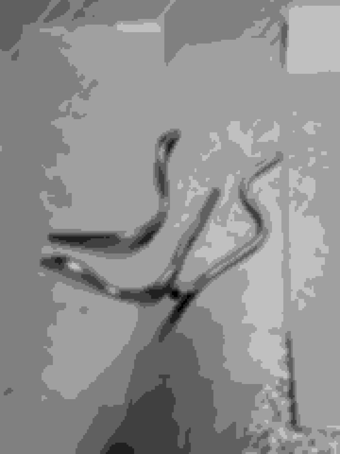
The piece of nicopp on the left comes from the Wix regulator/filter and then after the union, the hard line starts to go forward along the rear frame.
After doing that, I wasn't happy with the way the nicopp ran along the frame. I redid it. Did I mention that this project spanned almost 5 years?
I wanted the hard line to be one, unbroken piece but it wasn't possible due to my welded in subframe connectors. I had to cut the nicopp and add another union. Another possible leak point.
I got all the way up to the driver's side front frame rail and the real fun began. I spent so many hours bending tubing trying to get this just right. The frustration level was high but I kept at it and eventually bent a piece of tubing that I was happy with.
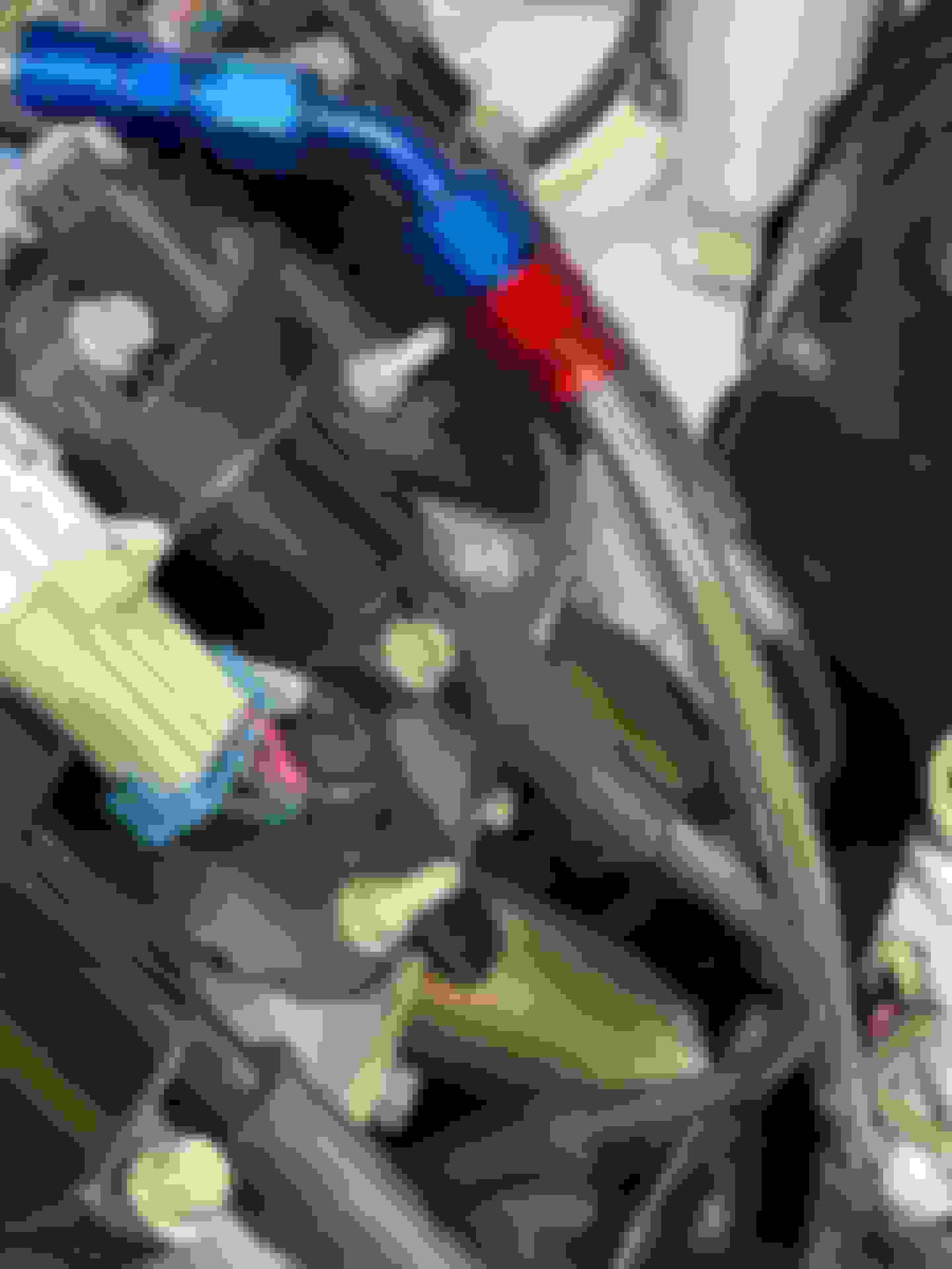
This next picture shows the AN fittings where the 3/8" nicopp transitions back into PTFE lined stainless steel hose into the engine compartment.
Here is the end of the line for the fuel plumbing! I spent way too much time on this fuel plumbing!
Here is a picture of some of my failures with the tubing up front. Multiple bends in multiple directions. I bet I spent 2 hours on each of those and two more hours on the fourth and final try. So much wasted time .
You did some nice work! Bending tubing is a real art form and requires a lot of skill, patience, and the proper tooling. I have ruined more length of tubing than I have actually turned into usable parts...
Thank you, Andrew. Kudos coming from someone like yourself who does first class work is definitely flattering!
I wasted as much tubing as I actually put into use. When I finally got done with the hard line work, I thought, "never again!" Who am I kidding? I'll do it again on the next project.
In posts 263-268 way back on 7 March of 2021, I mentioned/discussed relays for my headlights. The original OEM wiring for the headlights had the 12V power running to the dash headlight switch and then forward to the headlights. Not only that, the OEM wire was puny. This combination of long wire routing and small wire results in significant voltage drop by the time it gets to the headlight bulbs.
I upgraded the puny OEM factory wiring to US made, 12awg wiring. I purchased new plastic headlight bulb connectors and crimped the metal terminals onto the new wire. In addition, I installed relays to keep the 12V power wires very short. Now my headlight switch only acts as the trigger for the two relays; one for low beam and one for high beam.
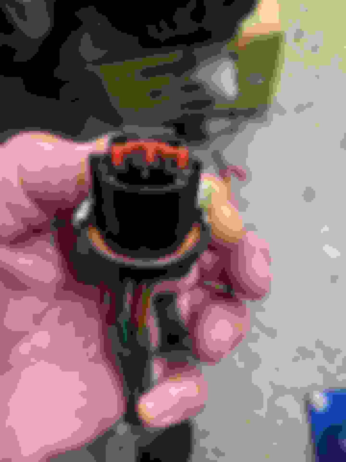
OEM connector and tiny wires.
Here are pictures of my new connectors, terminals and seals.
Yes, it takes a special crimp tool to crimp the terminals and seals.
Terminal and seal now crimped onto 12 AWG, thin wall, TXL wire.
The terminals get pushed into the plastic connector and then they lock into place.
Finally, a terminal position assurance (TPA) secondary clip is installed to finish it up.
I used these Hella 9007 halogen bulbs with a nice 80 watts of output on low beam. Maybe some time in the future I'll think about LEDs but for now, these inexpensive bulbs are doing fine.
IIRC, about 4 years ago when I "met" Andrew on this website, he introduced me to good, modern, properly done 12V wiring. One of the things that he recommended was the Bussmann RTMR fuse/relay box.
It uses micro or mini relays. At this time, I'm only using two of five available slots for relays. To the right side is where the fuses go and you'll see that in another picture.
Like most backyard, shadetree hobby mechanics, I knew nothing about these boxes. Nor did I know anything about quality 12V wiring work. Heck, I didn't even have a pair of decent crimpers! I got on the internet to educate myself and I found this: Bodenzord
This guy's 6-part tutorial taught me so much about proper automotive wiring using modern, high tech components. Andrew did tell me that some of these components have been around since the 1990s. Anyway, this is stuff you probably won't find at Autozone, O Reilly or Advance Auto. You will find these components at Waytek or ProwireUSA or Customconnectorkits and numerous others online.
There is so much information in Bodenzord's tutorial. My head was spinning and even after reading it several times, I was still confused. Once I knew enough to start ordering parts and had them in my hands, things started to make more sense. I'm not even close to being an
expert on this stuff. There are so many different components and I only work with them occasionally. If I were a pro working with them everyday, maybe I'd know this stuff very well. I frequently refer back to Bodenzord's tutorial, the Waytek hard copy catalog or just back to the internet to refresh my memory on Metri-Pack and Weather Pack. These are the only two lines of sealed connectors that I use. There are numerous different lines of connectors but those are the two that I use. Probably because that's what Bodenzord uses and teaches.
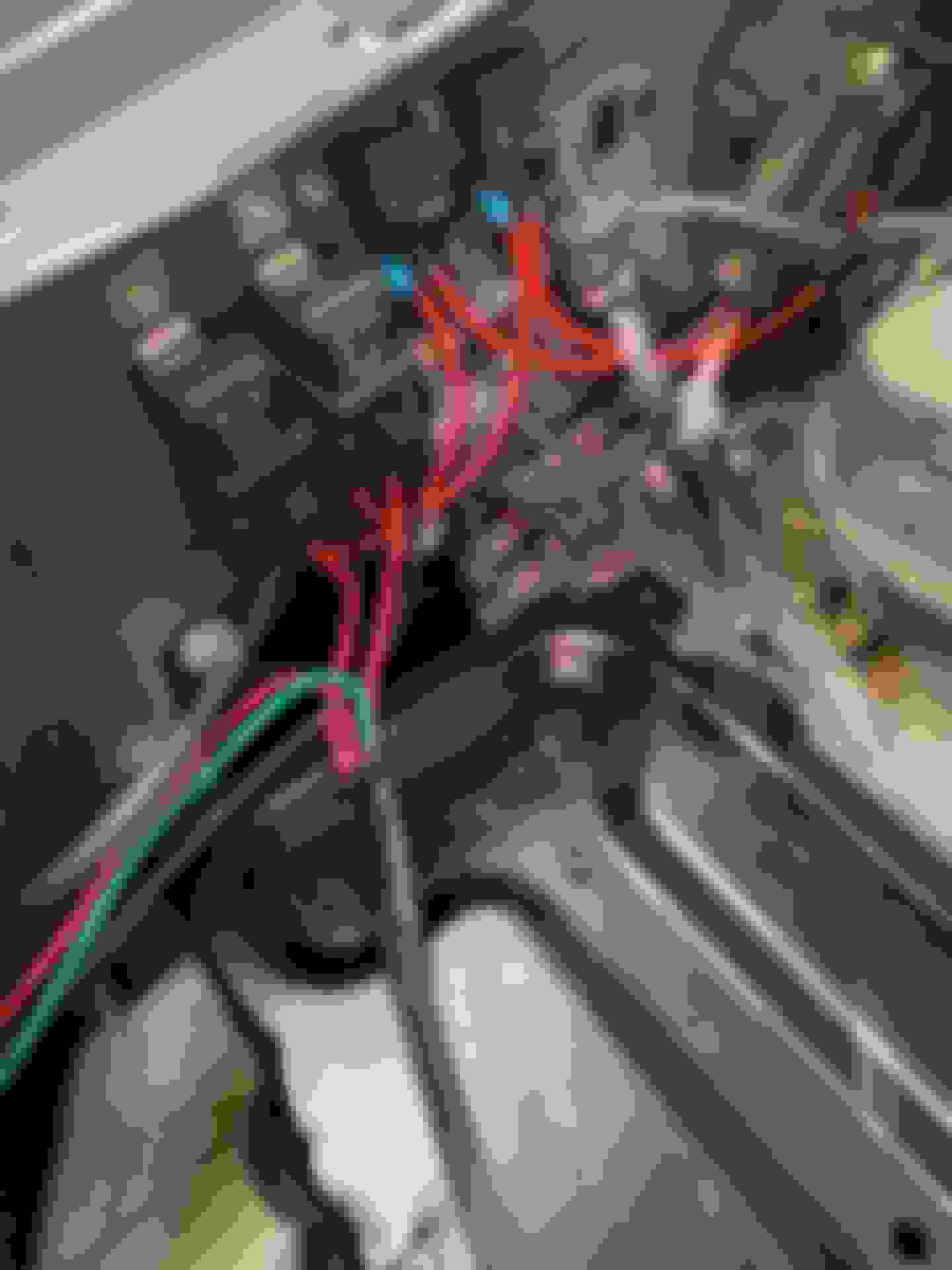
If any of you look at Bodenzord's tutorial, you'll see something like this. I wired up four of the five available relay slots with 10AWG TXL thin wall wire. You can see the green silicone plugs that close off all of the unused openings to waterproof this box.
Here it is with my two relays and fuses for the headlight low and high beams. You can see a sealed, Metri-Pack 280 connector at the bottom of the picture.
Thank you, Andrew! I'm really happy with the way the Bussmann box turned out.
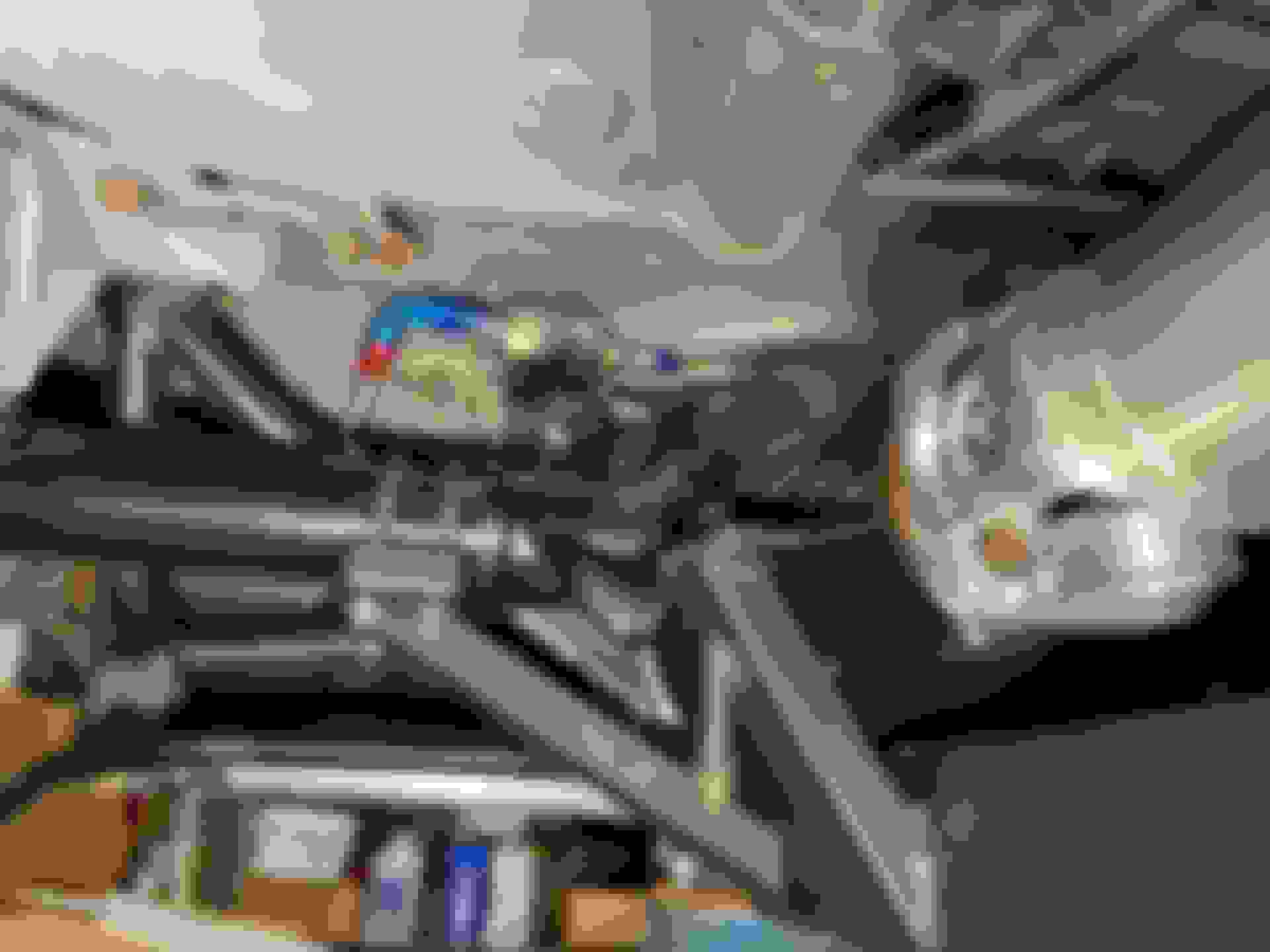
Here is a picture of the headlight relays/fuses I installed in my 2001 Ford F250SD diesel truck in July 2021:
I think the truck relay installation turned out very well and it sure does work well. However, the Bussmann relay/fuse box is definitely slick and way more tidy
Back on 3/7/2021 in post #269, Michael Yount asked if I was going to install the battery in the trunk. I'd never done that and since a lot of hot rodders do mount their battery in the trunk, I wanted to try it. First I had to weld up some holes in the trunk floor that the previous owner had drilled when he tried to trunk mount his battery.
Cleaned up and ready to weld.
I'm a complete welding rookie. I was so surprised to not blow any holes in this thin sheetmetal!
A little rattle can white paint to keep the welds from rusting.
I used 00 AWG US made welding cable from the trunk mounted battery up to the starter. I decided to run the cable through the inside of the car.
Here is the hole I drilled in the firewall for the 00 welding cable to pass through. The big hole is for the OEM AC system so I couldn't use it.
Here is the nylon cable gland that I used for the cable to pas through the firewall. Yeah, it's going to receive a lot of heat from the passenger side header but it will have heat protection wrap over the outside of it. I'll keep an eye on it next summer when it's really hot.
This is a china made, Amazon purchased hydraulic crimper for large gauge cable. I paid less than $40 about 4 yrs ago for it and it works pretty good. If I were a pro, I'd buy a better, USA made crimper for hundreds of dollars. For the hobby mechanic, this works just fine.
This is the back end of the long rear to front 00 AWG cable. I use "military style" battery terminals that this cable lug bolts up to.
This is the front end of the cable. The 90 degree lug will bolt to my starter. The blue and red tool is a large gauge cable stripper. It's made in Germany. It's not the easiest tool in the world to use properly and reviewers complained about it. Still, as you can see, it does a very good job of cleanly cutting and stripping the cable jacket.
One is the main fuse for the 00 AWG cable going to the starter. The other fuse is for my stereo's power amplifier mounted in the trunk.
This is everything mocked up with an old battery. You can see the military style battery terminals that I mentioned in my last post. I really like them and have been using them for a number of years on multiple vehicles. I do have nice black and red covers for the terminals that really finish off the installation.


 12-01-2023, 09:57 AM


 !
!


 .
.