


LS1 Swap FAQs
With regard to Stu Cool's post ^^^
A fitting similar to the one shown in the picture can be purchased at any LAPS (local auto parts store). I got the vertical one (no bend) at Advance Auto Parts in the screws/washers/fittings section. It was their part # Dorman 43275 for the straight up one. Here is a link to buy online:
http://www.partsamerica.com/ProductD...rtnumber=43276
Auto Zone carries the same part, same part number also.
If you specifically want the 90� fitting, Mid America Fittings (midamericafittings.com) has it with part # 29ESB-42, your local hydraulic shop may carry this part, they can at least crossreference in their system if they are half worth a damn.
I also pulled these part numbers from the Dorman website, but cannot seem to find them anywhere:
Dorman E1720 us a 1/4 tube to 1/8 NPT (90� fitting)
Dorman 323307 is 5/16 tube to 1/8 NPT (90� fitting)
Dorman 3040 is 5/16 tube to 1/8 NPT (90� fitting)
Dorman 492-046 is 5/16 tube to 1/8 NPT (90� fitting)
Dorman E1712 is 5/16 tube to 1/8 NPT (90� fitting)
And. realistically, a 5/16" tube is close enough to a 1/4" tube that it really ain't gonna matter that much, and the 5/16" tube adapters above would work fine. This isn't rocket science, it's a freakin' coolant tube.
Big note: a 1/8-27 pipe tap is required (not 1/8-28!).
For *all* NPT threads a sealant compound or Teflon tape must be used for a leak-free seal. (per engineeringtoolbox.com's page on NPT threads)
Drill your hole with 21/64 [.328] drill bit (11/32" [.344] will also work, so will 5/16" [.313]) to get the hole ready for threading. Use grease on the bit to catch filings and attach vacuum on the water pump to pull shavings out. Stu (check post before mine in this thread) recommended .336 decimal drill bit in his post, but I couldn't find one, and .008" plus or minus when dealing with a tapered pipe thread (NPT is tapered) will not be of consequence, much less .01"
As if it needs to be said, drill perpendicular and tap the hole carefully. Thread slowly and make sure you stay perpendicular to the hole while making it and threading it.
Teflon tape or use thread sealant (blue threadlock) for your brass fitting and thread it until tight DO NOT OVERTIGHTEN or you might crack the water pump housing
I plan on doing this mod over the week (edit: we're now at 11/15/2006 and still not done, gotta buy the drill bits)
As a point of note: Some people have argued that you should put your steam line vent into the highest possible point on your engine or the steam will not get out of the line. This means using the petcock provision on the lower part of your radiator COULD be bad. I honestly do not have advanced enough knowledge of the engine itself to say for sure, and I am not sure if anyone at this forum is truly qualified to answer this mystery with any degree of certainty.)
Last edited by shifty`; Nov 15, 2006 at 09:40 PM.
Launching!
Joined: Dec 2005
Posts: 213
Likes: 2
just a helpful piece of info for anyone swapping a GTO LS motor oilpan to an F-body oilpan setup....you HAVE to push the oil dipstick plug out the motor to use the f-body setup. the gto setup places the stick into the pan- whereas the f body places it into the motor!!!!!! I realized only after torquing the pan in place........duh...(you cant grab it with a magnet either...) 
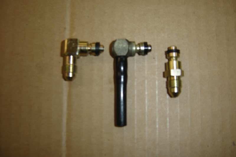
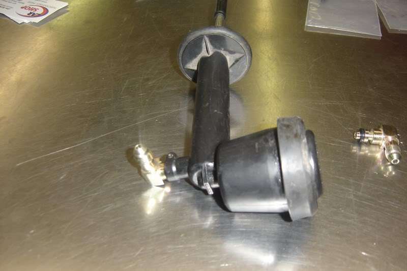
I have been on a quest to convert my clutch line over to my s-10 Clutch master and have come up with some quick connect fittings that allow me to use -4 lines and ditch that quick disconnect.
This fitting Will install in the place of the stock style fitting and uses the stock roll pin. This can be used in almost all late model gm clutch masters and slaves. You can remove the stock f-body fitting from the throw out bearing or from the slave and install this..... these are kind of expensive but being able to convert the stock slave to a -4 style fitting is well worth the cost.
I snapped a few pics and can get you guys some part numbers If you want.
LS1 Tech Stories
The Best V8 Stories One Small Block at Time

6 Common C5 Corvette Failures and What's Involved In Repairing Them
Pouria Savadkouei
Retro Modern Bandit Pontiac Trans AM Comes With Burt Reynolds' Autograph
Verdad Gallardo
Top 10 Greatest Cadillac V Series Performance Models Ever, Ranked
Pouria Savadkouei
Top 10 Most Powerful Chevy Trucks Ever Made!

Hennessey's New Supercharged Silverado ZR2 Has 700 HP
Verdad Gallardo
Coachbuilt N2A Anteros Is an LS2-Powered C6 Corvette In Italian Clothes
Verdad Gallardo
Awesome K5 Blazer Restomod Comes With C7 Corvette Power
Verdad Gallardo
10 Camaros You Should Never Buy

10 LS Engine Myths That Refuse to Die
Verdad Gallardo I wanted to add pics to go along with my post (#41) at the top of this page.
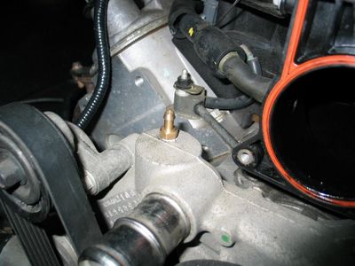
I went ahead and drilled and tapped my steam line and I know how everyone loves seeing pictures, so ...
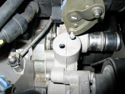
Here is the 11/32" hole drilled in the top of the water pump. In retrospect, I would have preferred to drill it with a 21/64 bit, which I have, but I'm a retard.
To further drill home my "after the fact" realizations, if I'd have been smart, I would have removed the TB before starting this whole process. It only has three bolts holding it in. I was trying to do everything in my power to dodge that bullet, though....
(Note: I put grease on my bit and duct taped a piece of radiator hose to my vacuum and hooked it up to the water pump while drilling to pull shavings. I am hoping this was sufficient...or I might be up **** creek)
... and here is why it would have been smart to remove the TB! My all-standard tap and die set only had this beast of a handle to work with, so I got stuck with using it. Off came the TB, and I pulled the water nipples out with some vice grips while it was out
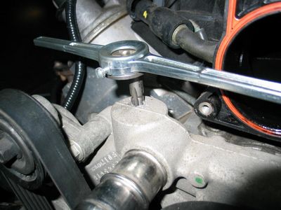
This hole was threaded for a standard 1/8-27 thread (DO NOT use a metric 1/8-28). This is going to sound crazy to some, but I do this often: I popped the tap into my electric drill at the lowest torque possible and started the thread this way just enough to get the bit set, then came in with my handle. This is the easiest way I've found to tap a vertical hole without the tap shifting on you. I do not condone this as the "proper" way to do things and recognize the huge potential for anyone who does not normally start a thread this way to seriously, seriously screw up your stuff..
My philosophy: If I screw it up, oh well, go buy another water pump and project gets set behind another 6 hours worth of work and $75-125. Drop in the bucket, at this point.
Again, vacuum was on while tapping the hole to get fragments.
Teflon tape or thread sealant (blue or otherwise) is required on all pipe fittings in homes, so I used it here also (tape). I couldn't find a 90� elbow with 1/4" NPT male to 1/8" tube, so here is my vertical piece, which works just as well. Dorman part #43276, available at your local auto parts store.
The 1/8" steam line was then routed under the edge of the intake, and attached on both sides with factory clips.
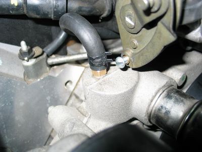
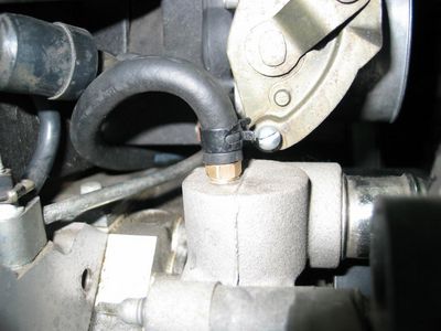
I am hoping there will not be a leak, but I'll never know until I fire it up. Custom radiator hoses are on the way, but won't be here till after holidays.
I went ahead and drilled and tapped my steam line and I know how everyone loves seeing pictures, so ...
Here is the 11/32" hole drilled in the top of the water pump. In retrospect, I would have preferred to drill it with a 21/64 bit, which I have, but I'm a retard.
To further drill home my "after the fact" realizations, if I'd have been smart, I would have removed the TB before starting this whole process. It only has three bolts holding it in. I was trying to do everything in my power to dodge that bullet, though....
(Note: I put grease on my bit and duct taped a piece of radiator hose to my vacuum and hooked it up to the water pump while drilling to pull shavings. I am hoping this was sufficient...or I might be up **** creek)
... and here is why it would have been smart to remove the TB! My all-standard tap and die set only had this beast of a handle to work with, so I got stuck with using it. Off came the TB, and I pulled the water nipples out with some vice grips while it was out
This hole was threaded for a standard 1/8-27 thread (DO NOT use a metric 1/8-28). This is going to sound crazy to some, but I do this often: I popped the tap into my electric drill at the lowest torque possible and started the thread this way just enough to get the bit set, then came in with my handle. This is the easiest way I've found to tap a vertical hole without the tap shifting on you. I do not condone this as the "proper" way to do things and recognize the huge potential for anyone who does not normally start a thread this way to seriously, seriously screw up your stuff..
My philosophy: If I screw it up, oh well, go buy another water pump and project gets set behind another 6 hours worth of work and $75-125. Drop in the bucket, at this point.
Again, vacuum was on while tapping the hole to get fragments.
Teflon tape or thread sealant (blue or otherwise) is required on all pipe fittings in homes, so I used it here also (tape). I couldn't find a 90� elbow with 1/4" NPT male to 1/8" tube, so here is my vertical piece, which works just as well. Dorman part #43276, available at your local auto parts store.
The 1/8" steam line was then routed under the edge of the intake, and attached on both sides with factory clips.
I am hoping there will not be a leak, but I'll never know until I fire it up. Custom radiator hoses are on the way, but won't be here till after holidays.
Last edited by shifty`; Nov 27, 2006 at 11:55 AM.


Anybody who happens to be doing a rebuild, the part numbers for the GM inner torque to yield main cap bolts are 12560272 and 12560373. You need both part numbers for the tall studs and bolts.
Last edited by pist0lpete; Jul 17, 2008 at 04:30 PM.
Launching!
Joined: Dec 2005
Posts: 213
Likes: 2
in case anybody needs help on radiator hoses, i have found that PEP BOYS carries a hose, part number (e)71189, which is the correct 1 3/4 in and out,in a Z shape,all 90 degree angles, which i found to be perfect in an a-body with ls1 and 04 gto stock radiator setup. (upper hose) it has an overall long distance to span that windtunnel nose on my 71 monte!! 

Staging Lane
Joined: Sep 2006
Posts: 73
Likes: 0
Just thought I'd throw this option in here for more FPR fittings. There has been issues with finding the Russell fittings so I stumbled onto these. It eliminates the need to find someone to flare a cut end of the dorman tube. 3/8" Male Quick Connect to -10 AN male coupler. Made by aeromotive.


GM has a swap guide book thats called;
LS1 Engine Kit Installation Guide
PN 88959384
Its a good overview of all the little things needing done and has a pretty solid compilation of wiring schematics and ALL the pinouts and wiring diagrams along with trouble codes and whatnot. Handy piece as its all printed and bound with pics ( black and white mind you ) It doesn't really say anything that cant be found with here with endless searching but its all in one book.
Of course I find this thing after I'm done but it might help someone else so good luck on your swap!
*edit* I thought I should also add that it has good descriptions on most mechanical items,sensors and functions as well. Also a troubleshooting guide that is tailored for swappers not stock use.
Last edited by cam; Feb 18, 2007 at 12:59 PM.

Teching In
Joined: Mar 2007
Posts: 6
Likes: 0
Originally Posted by Elec87
I have been on a quest to convert my clutch line over to my s-10 Clutch master and have come up with some quick connect fittings that allow me to use -4 lines and ditch that quick disconnect.
This fitting Will install in the place of the stock style fitting and uses the stock roll pin. This can be used in almost all late model gm clutch masters and slaves. You can remove the stock f-body fitting from the throw out bearing or from the slave and install this..... these are kind of expensive but being able to convert the stock slave to a -4 style fitting is well worth the cost.
I snapped a few pics and can get you guys some part numbers If you want.
This fitting Will install in the place of the stock style fitting and uses the stock roll pin. This can be used in almost all late model gm clutch masters and slaves. You can remove the stock f-body fitting from the throw out bearing or from the slave and install this..... these are kind of expensive but being able to convert the stock slave to a -4 style fitting is well worth the cost.
I snapped a few pics and can get you guys some part numbers If you want.
Originally Posted by downset71
just a helpful piece of info for anyone swapping a GTO LS motor oilpan to an F-body oilpan setup....you HAVE to push the oil dipstick plug out the motor to use the f-body setup. the gto setup places the stick into the pan- whereas the f body places it into the motor!!!!!! I realized only after torquing the pan in place........duh...(you cant grab it with a magnet either...)
Couldn't pull the damn thing out so I prayed to God and just popped it down into the pan and used a magnet with an extension to fish it out! Since the pan is aluminum and the plug was not(thank God) I got lucky. Just something to keep an eye out for BEFORE the pan/engine is in the car. Last edited by SilverBullet73; Mar 26, 2007 at 05:12 AM.

Teching In
Joined: Jan 2007
Posts: 8
Likes: 0
From: dallas
what is the purpose of the steam hole? is it necessary to run on an 85 trans am ls1 swap?
Originally Posted by shifty`
I wanted to add pics to go along with my post (#41) at the top of this page.
I went ahead and drilled and tapped my steam line and I know how everyone loves seeing pictures, so ...
Here is the 11/32" hole drilled in the top of the water pump. In retrospect, I would have preferred to drill it with a 21/64 bit, which I have, but I'm a retard.
To further drill home my "after the fact" realizations, if I'd have been smart, I would have removed the TB before starting this whole process. It only has three bolts holding it in. I was trying to do everything in my power to dodge that bullet, though....
(Note: I put grease on my bit and duct taped a piece of radiator hose to my vacuum and hooked it up to the water pump while drilling to pull shavings. I am hoping this was sufficient...or I might be up **** creek)
... and here is why it would have been smart to remove the TB! My all-standard tap and die set only had this beast of a handle to work with, so I got stuck with using it. Off came the TB, and I pulled the water nipples out with some vice grips while it was out
This hole was threaded for a standard 1/8-27 thread (DO NOT use a metric 1/8-28). This is going to sound crazy to some, but I do this often: I popped the tap into my electric drill at the lowest torque possible and started the thread this way just enough to get the bit set, then came in with my handle. This is the easiest way I've found to tap a vertical hole without the tap shifting on you. I do not condone this as the "proper" way to do things and recognize the huge potential for anyone who does not normally start a thread this way to seriously, seriously screw up your stuff..
My philosophy: If I screw it up, oh well, go buy another water pump and project gets set behind another 6 hours worth of work and $75-125. Drop in the bucket, at this point.
Again, vacuum was on while tapping the hole to get fragments.
Teflon tape or thread sealant (blue or otherwise) is required on all pipe fittings in homes, so I used it here also (tape). I couldn't find a 90� elbow with 1/4" NPT male to 1/8" tube, so here is my vertical piece, which works just as well. Dorman part #43276, available at your local auto parts store.
The 1/8" steam line was then routed under the edge of the intake, and attached on both sides with factory clips.
I am hoping there will not be a leak, but I'll never know until I fire it up. Custom radiator hoses are on the way, but won't be here till after holidays.
Originally Posted by nathan44
what is the purpose of the steam hole? is it necessary to run on an 85 trans am ls1 swap?

Seriously though - if you're using a stock radiator from a GenIII vehicle, no worries, just use the factory provisions given.
Here's a battery wiring tip that may help people out:
With some minor modifications, it is really, really easy to adapt the factory '98-'02 F-Body battery cables to your situation. The factory F-body battery cables come with the following five leads (I'll number for reference later):
(+) Positive cable:
#1 - Large red (~2ga) = to starter
#2 - Smaller red (~4ga) = to the power/fuse/relay bulkhead (interior power)
#3 - Smaller black (~4ga) = to the alternator
(-) Negative cable:
#4 - Large black (~2ga) = main ground to block
#5 - Tiny black (~12ga) = ground to body, I think
Stock out of a 2001 TA WS6, my battery cables were pre-bundled as such:
#1 and #4 were bundled together, with # 1 terminating at the starter, and #4 terminating on the block roughly 2" in front of the starter solenoid. #2 and #3 were bundled together, running under the pulley system (along base of radiator) with #3 going to the alternator and #2 going to the main fuse/relay bus under the hood.
Here are my observations:
The loom used to bundle #1 and #4 has a hole in it where #4 exits it near the starter. Because #4 rgound terminates so far from the battery, the cable is too short for some applications. If you remove the wires from the loom, separate them, then remove the loom completely and flip it so the ground exits farther back, you can move the ground forward on the block to a more suitable location closer to the front of the car (I deleted my A/C compressor, so I bolted the ground to the threaded hole leftover). This will give you another 12-24" of negative battery cable to stretch to your battery.
To keep from hacking the stock cable and use it to my advantage for my fuse block wiring, I split the loom for #2 and #3 and used a new piece of loom to route #2 over to my fuse/relay bulkhead on the passenger's side, then re-wrapping the loom for #3 and running it to my alternator, as expected. This allowed me to use #2 power for my main bulkhead - ring terminal was already attached - and power distribution went from there. You can literally use the stock f-body relay case in your car if you really wanted - get that from a junkyard and save lots of $$$ buying relays.
If you absolutely must use a new positive cable, I found two setups that are suitable solutions:
1) Stinger makes a product with model # 'SGMSA', it is called "GM Battery Terminal Multiple Output". (pic attached below, in gold) Here is a link to a shop selling it for $13 as of the day of this post:
http://www.hifisoundconnection.com/S...id/0/SFV/30046
Essentially, this is a side-mount replacement for the stock battery cable, and it offers outputs for one 0 gauge wire (starter), one 4 gauge wire (alternator), and two 8 gauge wires (amps/internal power/etc.) You can make any clean custom cable you want by going to NAPA and getting the appropriate ring terminals, then screw down the wires into this battery terminal and you're in business.
2) Your local auto parts store (I used Advanced Auto) will have varying lengths of cables. I found a 78" side-mount red battery cable with a 12ga extension on it, cost is around $12. I picked up a terminal post with a stuf on it that allowed for a 7/16" ring terminal to be attached to it. Picture of the terminal post is attached in chrome, below. This can be used for the alternator run (4ga).
Bulk cable is expensive, it is cheaper to buy the 78" cable I just mentioned and hack the damned ends off of it - you'll pay 1/3 the cost of normal 0ga or 2ga wire by doing this.
In regards to the steam line, I was about to do the water pump mod when I found the water pump on the GTO LS1 is slightly different and doesn't have that convenient spot as the others.
It got me to thinking so I decided to see how this line was ran on my GMC HD 6.0L. Guess what? It simply goes from the cross-over line to a nipple on the bottom of the throttle body. I look at my GTO TB, and it has the same nipple, just capped off. The factory GTO line even had a splice in the line that looked as though its initial purpose was to just run it there. I just pulled out the splice and connected it to the TB.
Anyone see any reason why this shouldn't work?
Last edited by GTOpowered240sx; May 9, 2007 at 02:55 PM.