


5.3 wiring basics
nope, I mean C100 - Pink wire on C100 pin C goes into fuse block on connector C2 pin E2, and turns right around INSIDE fuse block and feeds out of connector C2 pin F2. Pink wire on F2 goes to PCM and Transmission.
this link might help too... http://www.lt1swap.com/vortec_truck_pinouts/1999.htm
this link might help too... http://www.lt1swap.com/vortec_truck_pinouts/1999.htm
But i still do not have any power to fuses,pcm1,ETC,inj1,inj2. Or the fuel pump relay switching on.
So on C100 pin C, do you have to route that to a pinout or what? im not getting that?
Im having issues with my tranny pulling up many codes.
So if E2 and F2 on the C2 connector have 12v the tranny should work properly? I think im missing a wire or something, cause i got ign power to pinout F2, and the tranny will shift through gears quickly and stay in 3rd gear afterwards, no downshifting....?
Last edited by wbwhiteboy; Jul 2, 2008 at 11:45 AM.
So disreguard what i said above^^ post #64. i must have just not been reading it right. But on C100 piout C, powers up pinout E2, and F2 on connector C2 ( no wonder i get confused so easy with all these numbers and letters ) but anyways, i got the power to those and just like before itll shift through the gears pretty rough, and stick in 3rd gear still. i need to go get it scanned again to see what codes are pullin now. I just need to buy a damn scanner is what i need to do. LOL!
Not sure if anyone can help me out still....
But im still popping up a couple codes. And the transmission will shift the gears quickly at startup, and then stay in 3rd gear the rest of the ride.
Maybe something to do with the TCC brake switch? what all needs to be connected for that, and where?
But im still popping up a couple codes. And the transmission will shift the gears quickly at startup, and then stay in 3rd gear the rest of the ride.
Maybe something to do with the TCC brake switch? what all needs to be connected for that, and where?
I have an 03 harness that I am converting from DBW to Cable throttle for my swap. The method my tuner suggested requires me to re pin my harness for an 01 ECU so I may use the earlier OS.
Im about to finish things up but need some confirmation on a few wires.
I am using this link for all function references http://www.lt1swap.com/vortec_truck_pinouts/2003.htm
C100 Pins in question
C - Brown- Ignition 3 Voltage
The wire feeds to this connector. The two pin connector has a ground that merges with others from this portion of the harness.

P- Dark Blue- AC low pressure sensor.
This wire feeds to this two pin connector which grounds at the same location as the pin C wire. What worries me is that a 3 pin pressure sensor plug already exists on another portion of the harness.

J- Light Blue but is listed to be Black/White (Engine ON Signal (w/SBA)) in the link I posted. The lack of congruence with the diagram has be concerned.
The wire goes to the alternator plug.
Another issue I am seeing in the diagrams is the Oxygen sensor wiring. The 2003 diagram shows wire C of the O2 sensors leading back to pins 72 and 74 at the PCM.
72-HO2S HTR LOW (from bank 1 sensor 1)
74-HO2 LOW CTRL (from bank 2 sensor 1)
Now on the 2001 diagram Pin C of the O2 sensors is simply show to be grounded at the left rear of the engine.
What do I do here? Will I be ok just grounding the wire that are show to feed the PCM on the 03 diagram?
-Ryan
Im about to finish things up but need some confirmation on a few wires.
I am using this link for all function references http://www.lt1swap.com/vortec_truck_pinouts/2003.htm
C100 Pins in question
C - Brown- Ignition 3 Voltage
The wire feeds to this connector. The two pin connector has a ground that merges with others from this portion of the harness.
P- Dark Blue- AC low pressure sensor.
This wire feeds to this two pin connector which grounds at the same location as the pin C wire. What worries me is that a 3 pin pressure sensor plug already exists on another portion of the harness.
J- Light Blue but is listed to be Black/White (Engine ON Signal (w/SBA)) in the link I posted. The lack of congruence with the diagram has be concerned.
The wire goes to the alternator plug.
Another issue I am seeing in the diagrams is the Oxygen sensor wiring. The 2003 diagram shows wire C of the O2 sensors leading back to pins 72 and 74 at the PCM.
72-HO2S HTR LOW (from bank 1 sensor 1)
74-HO2 LOW CTRL (from bank 2 sensor 1)
Now on the 2001 diagram Pin C of the O2 sensors is simply show to be grounded at the left rear of the engine.
What do I do here? Will I be ok just grounding the wire that are show to feed the PCM on the 03 diagram?
-Ryan
LS1 Tech Stories
The Best V8 Stories One Small Block at Time

6 Common C5 Corvette Failures and What's Involved In Repairing Them
Pouria Savadkouei
Retro Modern Bandit Pontiac Trans AM Comes With Burt Reynolds' Autograph
Verdad Gallardo
Top 10 Greatest Cadillac V Series Performance Models Ever, Ranked
Pouria Savadkouei
Top 10 Most Powerful Chevy Trucks Ever Made!

Hennessey's New Supercharged Silverado ZR2 Has 700 HP
Verdad Gallardo
Coachbuilt N2A Anteros Is an LS2-Powered C6 Corvette In Italian Clothes
Verdad Gallardo
Awesome K5 Blazer Restomod Comes With C7 Corvette Power
Verdad Gallardo
10 Camaros You Should Never Buy

10 LS Engine Myths That Refuse to Die
Verdad Gallardo i dont mean to cut anyone off or anything but i feel intimidated. i have a 5.3 in my 86 camaro, had the pcm tuned and vats removed, emissions removed, tcm removed to accomodate my 700r4 conversion. my question is, i have the harness and fuse block, i also have c100 and c152 and i do believe theres another plug.
*i have battery power to the starter, solenoid is on a push button start-it turns over.
*my fuel pump(walbro) works, and i have fuel going to the rails.
*how do i get the ignition to work. it wont start. I have been reading this thread but kinda became confused.
i seriously need an idiots guide to fuel injection.
my batt. kill switch, i think,...is working like "hot at all times"
but for to get ign "run", what wires do i need to splice and connect or whatever to have this work, by the way i will be putting it on a toggle...the steering coloumn ign switch and wiring is gone as well as any kind of wiring in this car, except lights and anything ive put on toggle.
thanks in advance, hope to get this thing started up soon.
i know i'm bumping an old thread, but i'm extremely confused. i don't have one of these plugs/connectors shown in this thread. my pullout came with the engine wiring harness and ecu and a few cut wires. an 05 5.3.
do i need all these connectors? how do they connect to the maine ecu/engine harness?
do i need all these connectors? how do they connect to the maine ecu/engine harness?
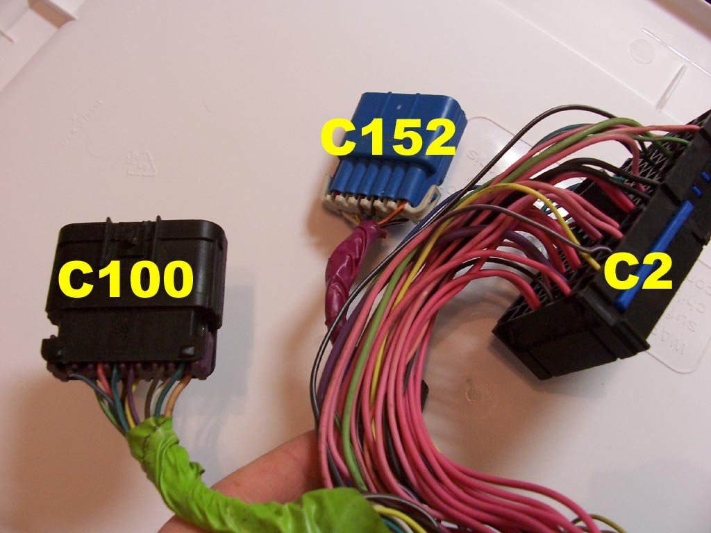
So you are missing the plugs, C2, C100, C152 as pictured at top of this thread?
If these are missing, and you want to modify harness you're self, You'll need to trace pins back to PCM for stuff like fuel pump relay, serial data lines, etc. you'll need to trace the pink wires back to everything that gets 12v+. Coils, injectors, oxygen sensors, trans, maf, etc.
If these are missing, and you want to modify harness you're self, You'll need to trace pins back to PCM for stuff like fuel pump relay, serial data lines, etc. you'll need to trace the pink wires back to everything that gets 12v+. Coils, injectors, oxygen sensors, trans, maf, etc.

Bump for some more questions. I know, I’m bringing this back to life, but... I’m in the process of modifying my ’00 LQ4/4L80e harness per this and a write-up on lt1swap.com. So far I’ve been able to pull out most of the pins on the engine harness itself (connector C2) and PCM connectors, but I’ve got a couple questions.
First, a little background. I’m using the stock harness from an '00 Silverado with the same setup that came out of the truck (LQ4/4L80e). I’m installing this in a ’71 Nova. I plan to run an aftermarket torque converter and eventually AC (not right now though), and I’m running Auto Meter electric gauges (speedo, tach, oil pressure, water temp). I just rewired the entire car with an American Autowire kit, and plan to use the underhood truck fuse block for the engine harness.
1. I’ve deleted connectors C152 and C153, but I’m confused on C100. The mating connector traces to two or three other connectors, which in turn contain a few other wires. A couple even connect into smaller fuse panels. Am I to keep these others as well? And if so, what exactly do I do with them?
2. What wires should I keep for the AC system if I plan to run AC in the future (most likely an aftermarket setup)?
3. Jeepinpete mentioned moving pin F2 on connector C2 to pin B9. I take it I can then delete pin E2 (and pin C on C100)?
4. I noticed that there's two wires in C100 that are labeled 'Serial Data Signal (Class 2)'. Which should I delete, if either?
Thanks guys. This thread has been immensely helpful. Attached is what I've done so far (incl. notes) to connectors C2, C100, C152, and C153. Please review and let me know if there's anything else I can delete (or should add back in).
-Trev
update - got some info from the guy who put together lt1swap.com. this is what i'll do with connector c100:
C delete, then do the F2 to B9 modification per jeepinpete
E To brake switch out via normally closed relay
G Check engine light
H Diagnostic port pin 2
M delete (SD2 wire #2)
R Keep just in case ('Fused Automatic Trans Shift Lock Control Feed')
Also, I'm deleting all AC wires.
C delete, then do the F2 to B9 modification per jeepinpete
E To brake switch out via normally closed relay
G Check engine light
H Diagnostic port pin 2
M delete (SD2 wire #2)
R Keep just in case ('Fused Automatic Trans Shift Lock Control Feed')
Also, I'm deleting all AC wires.


Teching In
Joined: Jan 2009
Posts: 6
Likes: 0
Hey guys, I am attemtping to modify my wiring harness for my 2006 6.0 motor that is going into my Jeep.
Based on my planned setup:
- SM465 Manual transmission (motor originally came with a 4L60 mated to it)
- VATs, emissions, etc. removed
- No computer controlled A/C (am going to wire around it)
- Cooling fan controlled by PCM
- don't need cruise control
- Need output from Chevy computer for aftermarket gauges (voltage, oil pressure, coolant temp, tach, and speedometer)
- Drive-By-Wire
...i have come up with my best shot at figuring out what wires I need from the PCM to go to external connections, what wires I need to go to the fuse panel, and roughly how everything needs to be wired. I've attached a few links to some scanned pinout sheets that i've marked up with my own comments.
For the PCM, I highlighted all of the wires in pink that I feel I don't need, and those that are going to external connections in blue. I also put a red dot next to the ones I think I need for gauges (not sure which one I need for voltage gauge). Problem is I have no idea if I am correct since I suck at wiring in general and have never done this before. If anyone has the time, and could skim through and make sure I'm not removing something that I will end up needing that would be much help. Also, below I've listed all of the connections that I am unsure of. Since I'd like to remove as much as possible from the harness, I'm curious as to which of these I need and which I don't.
http://www.4shared.com/file/10556725...M_Pinouts.html
C1
14/15 - UART Serial Data
33 - TCC Brake Switch (do I really need this if I am running a manual transmission?)
35 - CPP Switch Signal (M/T)
38 - Damping Lift/Dive
C2
10 - Medium resolution Engine speed signal
18 - Clutch start switch signal
22 - AT ISS High Signal (4WD with MT1)
23 - AT ISS Low Signal (4WD with MT1)
49 - VSS (this is another VSS signal, I'm assuming it's an input from the speed sensor, and the other pin 50 is the output?)
59 - Crank Voltage
70/71 - GMLAN Serial Data (HP2) - (pretty sure I don't need this since the HP2 is the hybrid motor, just making sure)
I did the same thing with the fuse pinouts, only I highlighted the ones I felt I needed. There is not much info on the actual pinout list as to what each pink wire is used for (most just say "Ignition 1 Voltage", so I checked my wiring diagrams and was able to determine what most of them were for. Again, I've scanned and attached a printout.
http://www.4shared.com/file/10556716...l_Pinouts.html
From what I can tell, the majority of the wires are coming from C2 Underhood (all pink, and the 2 orange for constant 12v to the PCM). There are a couple I'm not certain about - E11, F8 and F9. I'm pretty sure I don't need F8/F9 but just wanted to be certain. Also, on the C100 connector, the only ones I thought I might need are highlighted as well (only 3 of them). I didn't see anything on C152 or C153 that I would need. Does that look correct?
I apologize for all the questions, just wanting to make sure I do this correct the first time.
Also, a big thanks to Brendan from lt1swap.com........his website was extremely helpful.

Teching In
Joined: Jun 2006
Posts: 8
Likes: 0
From: Alabama
I need help wiring my backup lamps. Here's a reminder of what I'm doing. I'm using a 2000 5.3 Vortec and 4l60e tranny using the under the hood fuse block. It's wired as discussed earlier in this thread. I thought this would be easy but the two back up light locations: Plug C1 Wire B10 has no power, C2 Wire A9 has no power etc. I think I need something to work with the Park/Neutral switch but I'm not sure what. Can anyone help with this. This is the ONLY thing that I need to finish wiring my car and it's driving me crazy. This should be easy... right? PLEASE HELP!!!
I'm in the middle of installing a 2000 Silverado 5.3 into a 1989 Silverado.
Engine is in I'm using the factory harness with under hood fuse panel. Walbro fuel pump.
I have hooked up as follows:
C100
C pink needs 12v+ key, to supply power to pcm and transmission
H serial data, dk green
C1 connector light grey color contains the starter solenoid wire, position C10, purple with white trace.
Connect this to the wire that went to your old starter solenoid.
A9, pink, is switched ignition return from the ignition switch.
Connect this to the circuit that used to power the ignition coil.
C3 connector( Lighting, red). F1, grey, is the fuel pump switched power. Connect directly to the fuel pump.
When I crank the key:
I don't get 12V at the pump but like a 2 volt spike when I first turn it to on.
I get 12V coming from C10
Fuel pump relay clicks.
I'm able to read from PCM with HPT and have disabled VAT's.
I can jump the solenoid with the screw driver and the engine cranks but not with the key? Any ideas