

nissan 240sx (S14) with Modded GTO pan (tons of pics)
 05-05-2011, 09:46 PM
#201
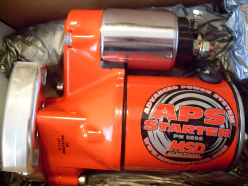
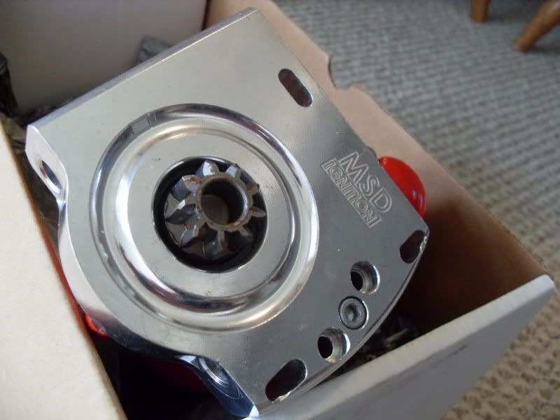
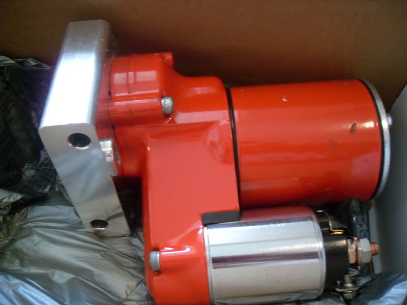
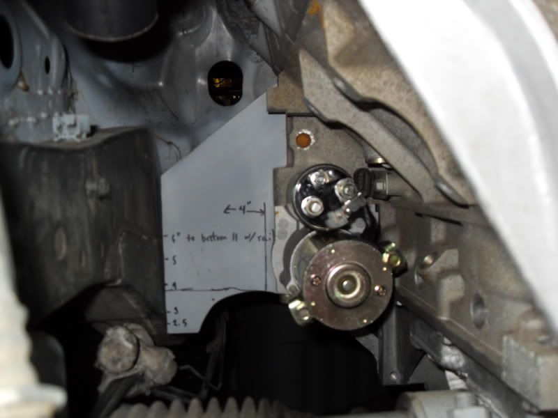
I originally bought this fancy, new, high-torque, MSD starter. It was supposed to be adjustable. But every adjustment hole just moved the reduction motor out further in the way! My header secondaries are 2" OD, and I needed the header to be almost no wider than the starter mounting bolts. Found a 2008 Avalanche 5.3 starter that looked like it might fit the bill. At $180 less than the MSD it seemed like it would be worth a shot. It works perfect!
The pretty 3 hp MSD starter that doesn't work
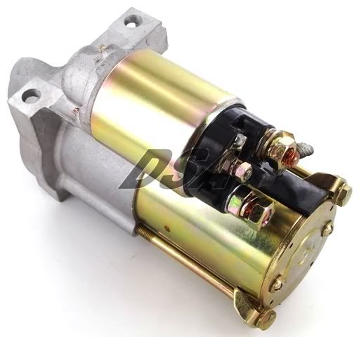
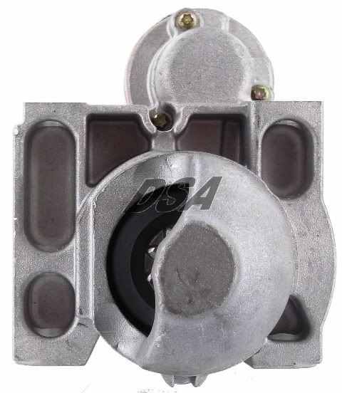
Here's the one I bought. Hopefully it won't get tired on my hi compression stroker motor. It gains me at least 5/16" of clearance over the MSD starter!
Starter Family: Delco PG260D
Type: PMGR
Voltage: 12 Volts
kW: 1.2 kW = 1.63 hp
Rotation: CW
Teeth/Splines: 9 Teeth/Splines
Pinion/Splines OD: 25.2mm / 0.992in
Mounting Hole 1: 10mm ID Unthreaded
Mounting Hole 2: 10mm ID Unthreaded
Approximate Weight: 7.5 lbs / 3.41 kg
And a little progress on the lower radiator mounts: I welded a stock s14 upper radiator mount below the powerbrace. Then welded 10mm rod to the bottom of the radiator that the stock upper mount style grommets fit onto. This will locate the radiator bottom in every direction, other than vertical.
The weather is finally decent, so I'm going to re-start my rear subframe reinforcement project soon.
I have a bunch of stuff that I want to paint the back of BEFORE I weld. What do you guys use? I've heard of guys using BBQ grill paint, and header paint... Any suggestions?
The pretty 3 hp MSD starter that doesn't work
Here's the one I bought. Hopefully it won't get tired on my hi compression stroker motor. It gains me at least 5/16" of clearance over the MSD starter!
Starter Family: Delco PG260D
Type: PMGR
Voltage: 12 Volts
kW: 1.2 kW = 1.63 hp
Rotation: CW
Teeth/Splines: 9 Teeth/Splines
Pinion/Splines OD: 25.2mm / 0.992in
Mounting Hole 1: 10mm ID Unthreaded
Mounting Hole 2: 10mm ID Unthreaded
Approximate Weight: 7.5 lbs / 3.41 kg
And a little progress on the lower radiator mounts: I welded a stock s14 upper radiator mount below the powerbrace. Then welded 10mm rod to the bottom of the radiator that the stock upper mount style grommets fit onto. This will locate the radiator bottom in every direction, other than vertical.
The weather is finally decent, so I'm going to re-start my rear subframe reinforcement project soon.
I have a bunch of stuff that I want to paint the back of BEFORE I weld. What do you guys use? I've heard of guys using BBQ grill paint, and header paint... Any suggestions?
 05-17-2011, 12:07 PM
#202
TECH Apprentice
iTrader: (1)
Join Date: Mar 2009
Location: LA
Posts: 356
Likes: 0
Received 0 Likes
on
0 Posts
Well first of all great build, i just threw mine together. Do you still have the msd starter? I just broke mine by trying to start the car when it was already running 
05-17-2011, 12:28 PM
#203
Sold the starter on ebay. It went pretty fast.
I have a million little pieces of reinforcement to cut out for the rear subframe and front tension rod mount, but I drew them on 12 or 14 gauge steel. A little too thick to cut with my snips, or nibbler. Anybody have access to a plasma-cutter anywhere near Long Island? I realy want to buy one, but it's not in the budget for awhile. I may give up and try and cut them out with my cut off wheel, but I'm not looking forward to it. My 25 gallon air compressor runs out of air every 5 minutes, then you have to wait 5 minutes... Ugh.
I have a million little pieces of reinforcement to cut out for the rear subframe and front tension rod mount, but I drew them on 12 or 14 gauge steel. A little too thick to cut with my snips, or nibbler. Anybody have access to a plasma-cutter anywhere near Long Island? I realy want to buy one, but it's not in the budget for awhile. I may give up and try and cut them out with my cut off wheel, but I'm not looking forward to it. My 25 gallon air compressor runs out of air every 5 minutes, then you have to wait 5 minutes... Ugh.
05-23-2011, 10:03 AM
#204
I've been a little concerned about using the manley pistons that I have with the oliver rods that I have. Originally I was going to custom order some low compression height Wiseco pistons, but the long block parts I got were just too good to pass up. My pistons have a standard compression height designed to be used with what has become the LSX standard 6.125" aftermarket rod. My oliver rods with the lube tubes are 6.200".
The taller rods necessitate a taller gasket. A stock LS7 gasket is 0.054" thick compressed. With the taller rods (presuming all of my measurements are exactly as advertised... unlikely) I'd need a 0.105" tall head gasket. Cometic stocks up to 0.125"! To put that into perspective for the import guys that's 3.2 mm thick!
Found this here on ls1tech about variances in LS2 deck heights by ChucksZ06 back in 2006
https://ls1tech.com/forums/ls1-domes.../t-543708.html
"My first ls2 block with 4" eagle crank and rods was .005 in the hole. I am now doing an ls2 block with a stock crank and 6.125 rods( same length as 402 build), same piston manufacturer and the pistons are .008 out. I think the stroke on the 4" crank was not quite right. So from my experience you pretty much have to mock up the parts or it is guessing. Good luck."
Keeping the top ring below deck seems like common sense. It's common for the crevice height (top of piston to top of top ring) on performance pistons to range from about 0.180 - 0.320". So presuming (what I consider) a loose quench of 0.035" and super tall 0.125" gasket you should still be safe with low crevice volume pistons all the way down to a crevice height of 0.160". Still that's a little too close if you're running a low crevice height pistons near 0.180".
9.240" stock LS1/2/3/7 Deck height
2.000" less 4" stroke/2
1.115" less my manley piston's compression height (was designed for a 6.125" rod)
6.200" less my lube-tube oliver pistons
puts me 0.075" out of the hole.
for a tight 0.030" quench I'd need a custom 0.105" thick gasket.
I also found Lingenfelters book on google. He mentions that he reccomends 0.250 crevice height for street engines, but has seen all the way down to 0.100" on all out N/A drag engines!
Good read:
John Lingenfelter on modifying small-block Chevy engines: high performance ...
By John Lingenfelter
http://books.google.com/books?id=GUC...height&f=false
05-27-2011, 06:58 PM
#205
I was pulling apart a Z32 rear subframe and noticed this reinforcement that the s14 doesnt have. Can't decide if it's worth replicating or not.
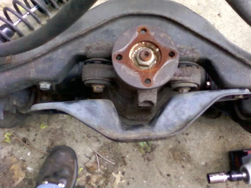
I also scanned the Ohlins instructions manual to pdf files, but they are of course in Japanese and I can't read them. If any one can help, or knows anyone that might be willing to translate them for please shoot me a pm and I'll email the pdf files to. Thanks guys!
I also scanned the Ohlins instructions manual to pdf files, but they are of course in Japanese and I can't read them. If any one can help, or knows anyone that might be willing to translate them for please shoot me a pm and I'll email the pdf files to. Thanks guys!
06-10-2011, 01:09 AM
#206
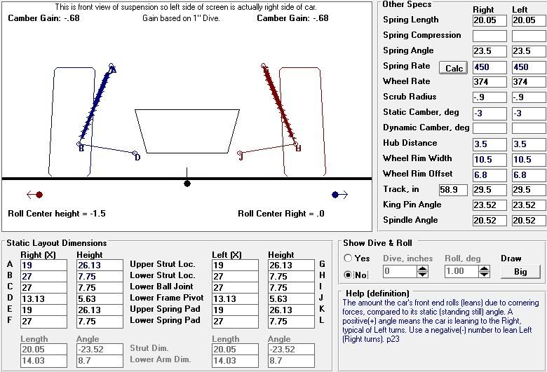
I finally got a chance to play with some suspension software! It's performance trends roll center program. All the measurements came off my s14. I used a ride height of 3.125" from the ground to the bottom of the crossmember. And my LSx crank centerline as the CG height came out to 10.625" above ground. All measuremens also presume 3 degrees of static camber.
Ideal camber curves have about 1 degree of camber gain per degree of roll. The senarios I plotted varied from 0.45 - 0.63 degrees of camber gain. Such is the strut...
Just from visualizing the geometry in my head I expected the set ups with roll center correction to have better and better camber gain as the FLCA angle further down towards the ball joint. This isn't the case! Improving the roll center, hurts camber gain, but not much. Who new?
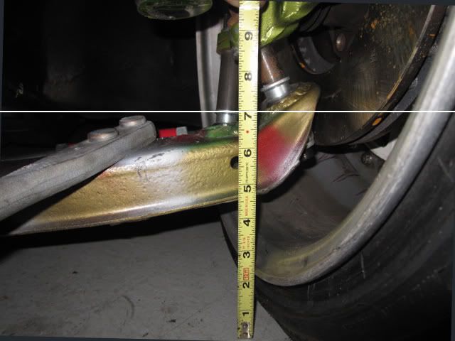
Before we can get to the nitty gritty of roll couple we need to talk about ball joints. I found this totally sweet pic in the roll center thread. From the pic I extrapolated that the stock ball joint is about 1.5". The whiteline and moonface pieces go for around $270, while the stockers (only 0.69" shorter) go for only $27!
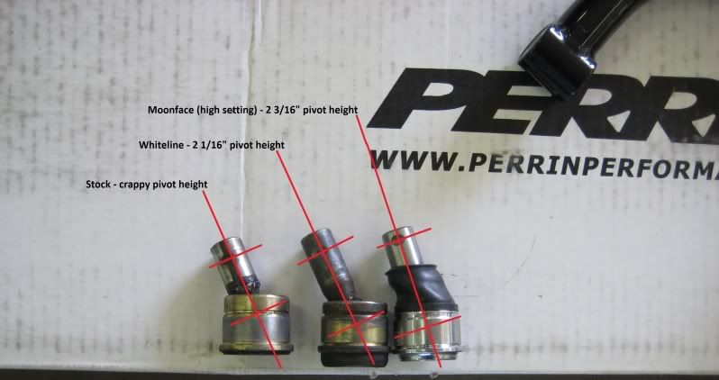
And here's an example of goin all hardcore with the ball joints. But notice that even after all this there's no more correction than the moonface offers. Looks a bit over two inches of from the ball joint articulation to mount. Of course with this kind of set up you can go bigger. But would you want to? Those bolts in single shear start to look real scary real fast.
So here's what it looks like without any correction:
roll center 1.5" below ground
With a ball joint that is >2" long:
you reduce the roll couple by 1.5" (or 14%), and at least the roll center is leve with the ground

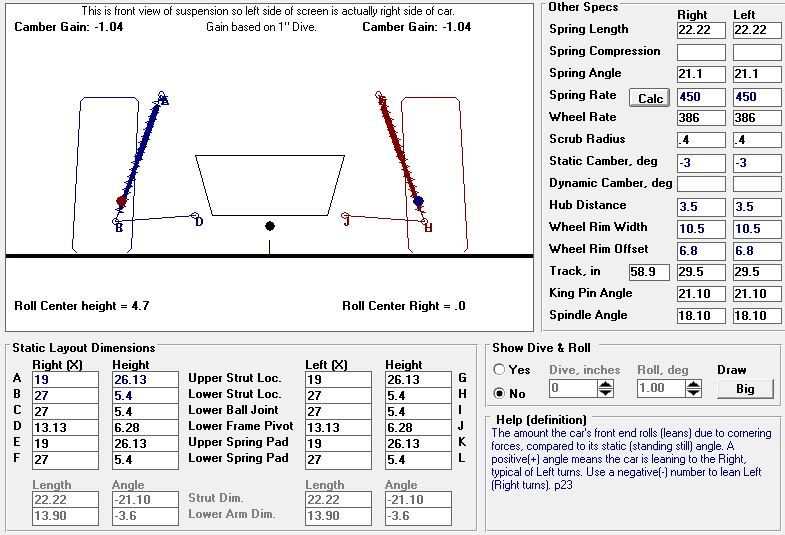
Now if you cut off the bottom of the spindle and weld in a big block of steel 2.35" tall, you'll get a lot more correction than the 0.69" that expensive ball joints buys you. Surprisingly raising the chassis mounting point for the FLCA doesn't do much. But in the following calc it's raised 0.66" just for Anti-Dive. Wih these two mods here's what you'll get:
A roll center height of 4.7" above the ground! Thats a roll couple that's been decreased from 12.125 to 5.925, for a roll couple that's only 48% of the original.
Ideal camber curves have about 1 degree of camber gain per degree of roll. The senarios I plotted varied from 0.45 - 0.63 degrees of camber gain. Such is the strut...
Just from visualizing the geometry in my head I expected the set ups with roll center correction to have better and better camber gain as the FLCA angle further down towards the ball joint. This isn't the case! Improving the roll center, hurts camber gain, but not much. Who new?
Before we can get to the nitty gritty of roll couple we need to talk about ball joints. I found this totally sweet pic in the roll center thread. From the pic I extrapolated that the stock ball joint is about 1.5". The whiteline and moonface pieces go for around $270, while the stockers (only 0.69" shorter) go for only $27!
And here's an example of goin all hardcore with the ball joints. But notice that even after all this there's no more correction than the moonface offers. Looks a bit over two inches of from the ball joint articulation to mount. Of course with this kind of set up you can go bigger. But would you want to? Those bolts in single shear start to look real scary real fast.
So here's what it looks like without any correction:
roll center 1.5" below ground
With a ball joint that is >2" long:
you reduce the roll couple by 1.5" (or 14%), and at least the roll center is leve with the ground
Now if you cut off the bottom of the spindle and weld in a big block of steel 2.35" tall, you'll get a lot more correction than the 0.69" that expensive ball joints buys you. Surprisingly raising the chassis mounting point for the FLCA doesn't do much. But in the following calc it's raised 0.66" just for Anti-Dive. Wih these two mods here's what you'll get:
A roll center height of 4.7" above the ground! Thats a roll couple that's been decreased from 12.125 to 5.925, for a roll couple that's only 48% of the original.
06-20-2011, 12:40 AM
#207
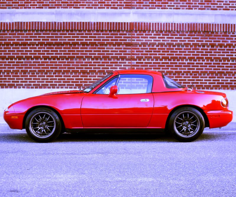
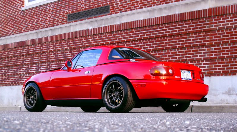
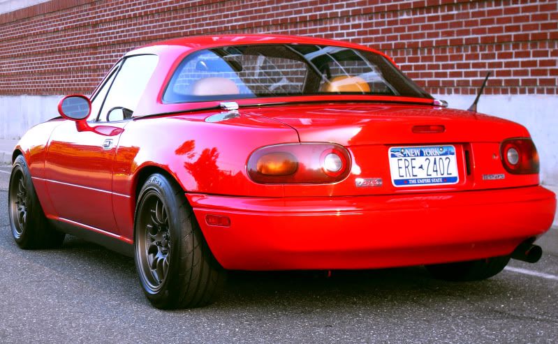
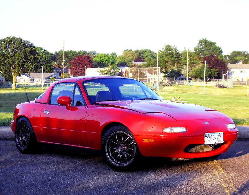
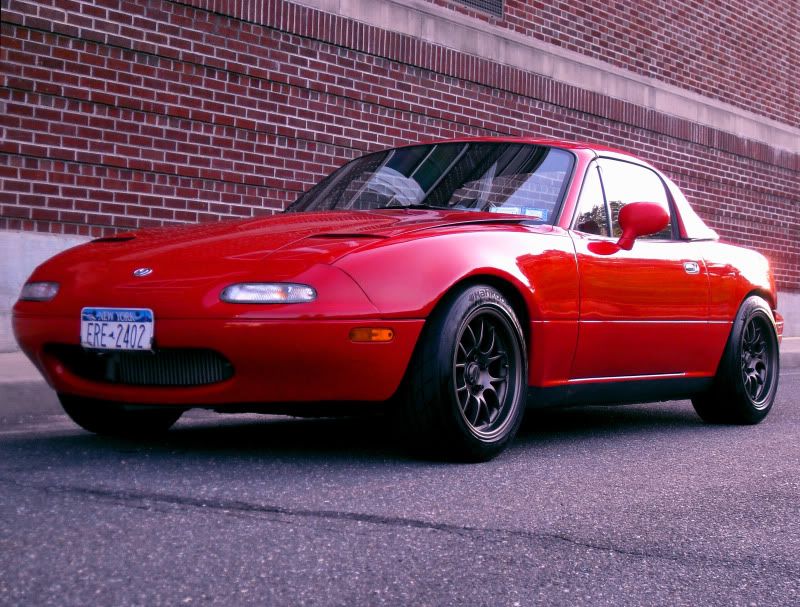
My miata is on ebay now, tell everyone you know who needs a 300 hp, 2200 lbs, whipple charged monster, that the funds will go to the good cause that is a 404ci L76 powered 240sx.
no reserve. Item # 130536000817
http://cgi.ebay.com/ebaymotors/Whipp...item1e648d4d31
Had a little photo shoot today too so check out the new pics!.


no reserve. Item # 130536000817
http://cgi.ebay.com/ebaymotors/Whipp...item1e648d4d31
Had a little photo shoot today too so check out the new pics!.
06-30-2011, 09:26 PM
#208
HioSSilver over on LS1tech has been runnin a 4th gen camaro with a multi-plate racing clutcha crate ls6 and doing 11.53 @ 122 1.90 60' (on 18's) with only 413 rwhp & 395 rwtq!! You'll notice his 60' is nothing special, I've seen plenty of Nissans do 1.60 60'. I think part of the explination for his awesome et per hp is due to the clutch's low MOI (moment of inertia).
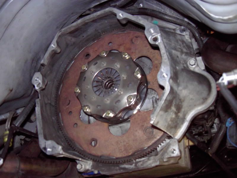
Here's a pic of his Tilton 5.5" triple racing clutch bolted to a button plate that is sandwiched between a stock auto flexplate and the clutch.
Been doing a bit more research on racing clutches in street cars, and was wondering if your 5.5 is still alive? And if you ever tried any other discs?
Yes it is. The first set of clutches (new) lasted 2.5 yrs. The next set lasted 1.5 yrs (used) and the set in it now is used 6mths. This is my dd. I really like this set-up. It cures all that clutch bullshit evryone goes through.
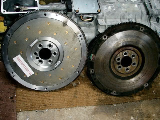
And a pic of a Zoom flywheel for an LS1 (left) next to a stock iron LS1 flywheel (right), (they are the same size, both with 153 teeth for starter engagement). The zoom flywheel can accomidate upto a full 12" clutch disc
Here's a list of the MOI of different clutches
Tilton Clutch Assemblies MOI (lb-in^2)
Includes: Clutch cover with diaphragm spring, pressure plates and floater plate(s)
(add 66 MOI and 2.5# to include the button
(add 87 MOI and 3.4# to include a Sonic ultra-lightweight flexplate)
13 4.4” Tilton carbon carbon 4 disc
21.4 5.5” Tilton 1 disc cerametallic
29.4 5.5” Tilton 2 disc sintered metallic (6#)
32.2 5.5” Tilton 2 disc cerametallic
52.4 7.25” Tilton 1 disc cerametallic
76.3 7.25” Tilton 2 disc cerametallic
89.6 7.25” Tilton 3 disc sintered metallic (10.2#)
99 8.5” Tilton 1 disc cerametallic
100.2 7.25” Tilton 3 disc cerametallic
158 8.5” Tilton 2 disc cerametallic
337 9.0” Mantic street dual sprung clutch (33.8#) cool set up!
>3200 11.5"? Stock LS2 flywheel and clutch (52#)
A good rule of thumb with racing clutches is that doubling a clutches weight will double its MOI, but doubling its diameter increase the MOI 4 times! Another rule of thumb is that increasing the clutches diameter 1.1" doubles the MOI.P
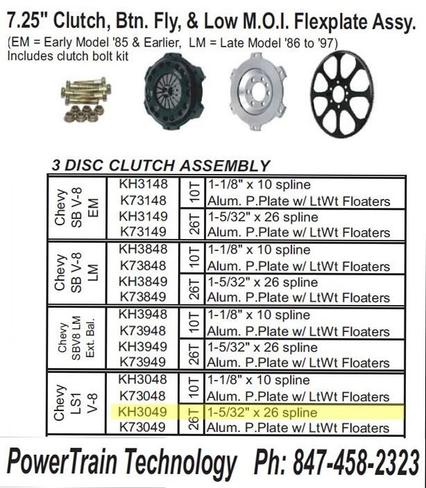
Here's PTTs set up. I was all excited because they were one of the first to introduce organic discs in race car, multi-plate sizes. But I spoke to their rep today who informed me that they don't reccomend their organic discs on any car over 400 hp regardless of how many discs. Bums me out, but maybe I'll call and talk to one of their engineers.
the "button" looks bigger in the pic than it actually is. It's inner 6 bolt holes line up with the flexplate's (flywheel for an automatic car)inner 6 bolt holes .
Here's a pic of his Tilton 5.5" triple racing clutch bolted to a button plate that is sandwiched between a stock auto flexplate and the clutch.
Been doing a bit more research on racing clutches in street cars, and was wondering if your 5.5 is still alive? And if you ever tried any other discs?
Yes it is. The first set of clutches (new) lasted 2.5 yrs. The next set lasted 1.5 yrs (used) and the set in it now is used 6mths. This is my dd. I really like this set-up. It cures all that clutch bullshit evryone goes through.
And a pic of a Zoom flywheel for an LS1 (left) next to a stock iron LS1 flywheel (right), (they are the same size, both with 153 teeth for starter engagement). The zoom flywheel can accomidate upto a full 12" clutch disc
Here's a list of the MOI of different clutches
Tilton Clutch Assemblies MOI (lb-in^2)
Includes: Clutch cover with diaphragm spring, pressure plates and floater plate(s)
(add 66 MOI and 2.5# to include the button
(add 87 MOI and 3.4# to include a Sonic ultra-lightweight flexplate)
13 4.4” Tilton carbon carbon 4 disc
21.4 5.5” Tilton 1 disc cerametallic
29.4 5.5” Tilton 2 disc sintered metallic (6#)
32.2 5.5” Tilton 2 disc cerametallic
52.4 7.25” Tilton 1 disc cerametallic
76.3 7.25” Tilton 2 disc cerametallic
89.6 7.25” Tilton 3 disc sintered metallic (10.2#)
99 8.5” Tilton 1 disc cerametallic
100.2 7.25” Tilton 3 disc cerametallic
158 8.5” Tilton 2 disc cerametallic
337 9.0” Mantic street dual sprung clutch (33.8#) cool set up!
>3200 11.5"? Stock LS2 flywheel and clutch (52#)
A good rule of thumb with racing clutches is that doubling a clutches weight will double its MOI, but doubling its diameter increase the MOI 4 times! Another rule of thumb is that increasing the clutches diameter 1.1" doubles the MOI.P
Here's PTTs set up. I was all excited because they were one of the first to introduce organic discs in race car, multi-plate sizes. But I spoke to their rep today who informed me that they don't reccomend their organic discs on any car over 400 hp regardless of how many discs. Bums me out, but maybe I'll call and talk to one of their engineers.
the "button" looks bigger in the pic than it actually is. It's inner 6 bolt holes line up with the flexplate's (flywheel for an automatic car)inner 6 bolt holes .
Last edited by GIGAPUNK; 06-30-2011 at 09:37 PM.
07-09-2011, 07:34 PM
#209
Had a nice little trip last week!

At first I was considering getting a 32 gallon, cause some day I'd like to go E85 which suck a TON of fuel. But I was worried about being able to get it out from the top of trunk. ATL makes a "shoebox" style container that has no flanges, so it's easier to drop from the bottom. Turns out the 32 doesn't come with a shoe box lid. The 32 was going to be pretty damn tall (would have almost hit he trunk torsion springs) anyways. The aluminum containers are supposed to only weigh 15 lbs compared to about 25 lbs for the steel.
So I got the 22B!
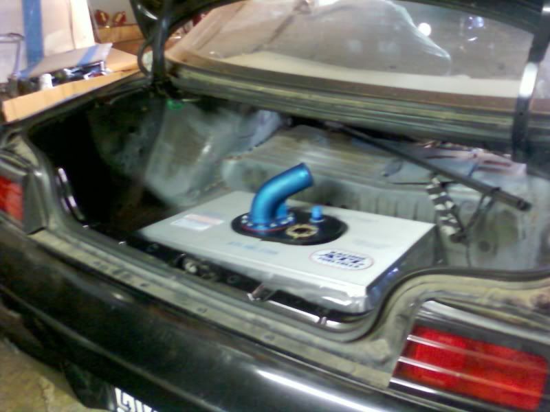
The 22B even fits from the top with no problem. So the shoe box lid wasn't needed.
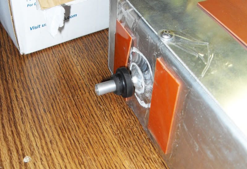
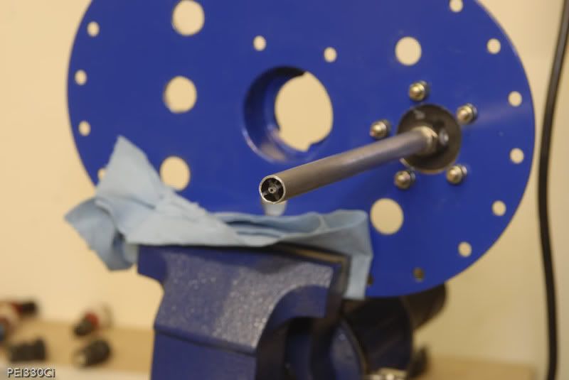
The Nascar surplus ATL lid I scored on ebay came with a huge 1.5" vent tube, which is absolutely unneccesary unless you plan on doing speed fueling refills. Otherwise a vent as small as AN-6 with a check ball (for roll-over) will sufice.
I read on more than one forum that fuel cells with very large vents can evaporate enough fuel to empty a small tank over a few months. The guys at ATL thought that was bull-****. Either way I was reading up on fuel vents. The stock system routes a small hose (probably ~3/8") to the charcoal canister mounted just infront of the passenger side rear bumper. The idea is that all of the fuel fumes get trapped there while the car is not running. A second (equally small) hose connects the other side of the charcoal cannister to the intake manifold. When the car is started, all of the stored fuel vapor is sucked into the combustion chamber via running vacuum. The charcoal canister weighs almost nothing, and is supposed to last the life of the vehicle. I am considerng installing a -6 check valve back to the original charcoal canister. And placing a fuel level sender where the 1.5" vent is.
The orignal ATL fuel level sender is non-mechanical. It is called a capasitive sender. They can be made almost any length, and can be set u for any resistive range to match different stock gauges. However, they have to be calibrated to one specific fuel type. A gauge set up for gasoline, will not read correctly once you pour in E85. ATL's newer gauge type is about $40 more expansive, is mechanical, has a set ohm range, and reads accurately regardless of fuel type. The fuel level senders are about the same diameter flange as my 1.5" nascar vent but the level senders have a 5 bolt pattern compared to the vents 8 bolt.
At first I was considering getting a 32 gallon, cause some day I'd like to go E85 which suck a TON of fuel. But I was worried about being able to get it out from the top of trunk. ATL makes a "shoebox" style container that has no flanges, so it's easier to drop from the bottom. Turns out the 32 doesn't come with a shoe box lid. The 32 was going to be pretty damn tall (would have almost hit he trunk torsion springs) anyways. The aluminum containers are supposed to only weigh 15 lbs compared to about 25 lbs for the steel.
So I got the 22B!
The 22B even fits from the top with no problem. So the shoe box lid wasn't needed.
The Nascar surplus ATL lid I scored on ebay came with a huge 1.5" vent tube, which is absolutely unneccesary unless you plan on doing speed fueling refills. Otherwise a vent as small as AN-6 with a check ball (for roll-over) will sufice.
I read on more than one forum that fuel cells with very large vents can evaporate enough fuel to empty a small tank over a few months. The guys at ATL thought that was bull-****. Either way I was reading up on fuel vents. The stock system routes a small hose (probably ~3/8") to the charcoal canister mounted just infront of the passenger side rear bumper. The idea is that all of the fuel fumes get trapped there while the car is not running. A second (equally small) hose connects the other side of the charcoal cannister to the intake manifold. When the car is started, all of the stored fuel vapor is sucked into the combustion chamber via running vacuum. The charcoal canister weighs almost nothing, and is supposed to last the life of the vehicle. I am considerng installing a -6 check valve back to the original charcoal canister. And placing a fuel level sender where the 1.5" vent is.
The orignal ATL fuel level sender is non-mechanical. It is called a capasitive sender. They can be made almost any length, and can be set u for any resistive range to match different stock gauges. However, they have to be calibrated to one specific fuel type. A gauge set up for gasoline, will not read correctly once you pour in E85. ATL's newer gauge type is about $40 more expansive, is mechanical, has a set ohm range, and reads accurately regardless of fuel type. The fuel level senders are about the same diameter flange as my 1.5" nascar vent but the level senders have a 5 bolt pattern compared to the vents 8 bolt.
07-10-2011, 11:28 PM
#210
Got my hands on Engine Analyzer Pro software. Seriously cool program. I have a top of the line i7 processor and 6 gigs of ram, and the computations can still take upto a minute! Crazy. I've been playing with options on my 404 with LS3 heads. After a lot of research I settled on a 238/244 cam. After playing wiht the new software that may change a bit. Here's some interesting things I learned while playing with the software:
1) don't need more than .604 exhaust lift
2) I'm not willing to loose >60 ft lbs of torque below 4000 rpm with a tunnel ram intake even if it gains me 50 hp up top.
3) decreasing intake duration from 238->232 lowers avg hp 1
4) increasing intake duration from 238->244 lowers avg trq 2
5) the only change w a big 90mmX1" spacer is a loss of 1 hp!
One thing that I was really interested in was exhaust valve duration. The LS3 heads are very unique in the world of modern performance heads in that the exhaust only flow 66.5% of what the intakes flow. This is considered pretty low. Unless you're talking about a modern Winston cup car. All of Comp cams off-the-shelf LS3 cams try to "overcome" the relatively poor exhaust flow by running a huge 15 degrees more duration on the exhuast lobe than the intake lobes. Normally this would be considered excessive on onything short of a full blown nitrous motor. And really didn't make sense to me.
My intake duration 238 + 15 = 253
I did multiple tests on the simulator. I would always add the extra duration to the exhaust opening in my tests, so not to change the overlap. And with comps 15 degree split I would loose between 5 and 15 ft lbs below 5000 rpm. In one simulation I lost 50 ft lbs at 3500 rpm with the greater exhaust duration! And I usually only gained 5-7 hp over 6000 rpm.
Then I thought maybe even my split was too much. My proposed 238-244= 6 degrees of split. Dropping down to only 3 degrees of split with a 241 exhaust duration picked up a huge 13 ft lbs at 3500 rpm and only gave up 1-2 hp above 5500 rpm.
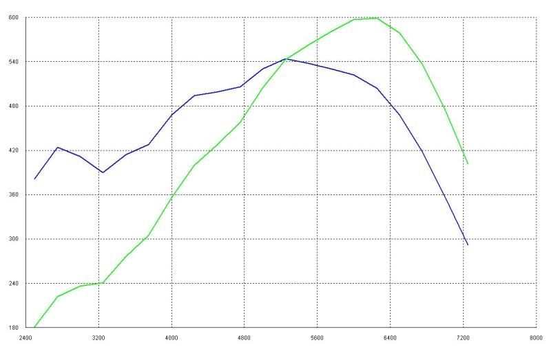
Here's the Winner cam as of right now.
238/240 112 +1 .612 lift in and ex
max trq 570 @5000, 479 avg 2500-7000 rpm
max hp 600 @6000, 436 avg 2500-7000 rpm
Every one warned me not to get my hopes up over 6300 rpm with the stock intake. And boy the Engine Analyzer doesn't disagree! This thing just falls on its FACE over 6500 rpm.
Here's an examply dyno produced by the program. These would be engine dyno numbers with a 300 rpm/sec accel rate, and with all accessories and a flywheel. Here the cam is retarded to -1! It trades 4 ft lbs down low for 5 hp up top compared to my +1 cam (that is 2 degrees more advanced.
1) don't need more than .604 exhaust lift
2) I'm not willing to loose >60 ft lbs of torque below 4000 rpm with a tunnel ram intake even if it gains me 50 hp up top.
3) decreasing intake duration from 238->232 lowers avg hp 1
4) increasing intake duration from 238->244 lowers avg trq 2
5) the only change w a big 90mmX1" spacer is a loss of 1 hp!
One thing that I was really interested in was exhaust valve duration. The LS3 heads are very unique in the world of modern performance heads in that the exhaust only flow 66.5% of what the intakes flow. This is considered pretty low. Unless you're talking about a modern Winston cup car. All of Comp cams off-the-shelf LS3 cams try to "overcome" the relatively poor exhaust flow by running a huge 15 degrees more duration on the exhuast lobe than the intake lobes. Normally this would be considered excessive on onything short of a full blown nitrous motor. And really didn't make sense to me.
My intake duration 238 + 15 = 253
I did multiple tests on the simulator. I would always add the extra duration to the exhaust opening in my tests, so not to change the overlap. And with comps 15 degree split I would loose between 5 and 15 ft lbs below 5000 rpm. In one simulation I lost 50 ft lbs at 3500 rpm with the greater exhaust duration! And I usually only gained 5-7 hp over 6000 rpm.
Then I thought maybe even my split was too much. My proposed 238-244= 6 degrees of split. Dropping down to only 3 degrees of split with a 241 exhaust duration picked up a huge 13 ft lbs at 3500 rpm and only gave up 1-2 hp above 5500 rpm.
Here's the Winner cam as of right now.
238/240 112 +1 .612 lift in and ex
max trq 570 @5000, 479 avg 2500-7000 rpm
max hp 600 @6000, 436 avg 2500-7000 rpm
Every one warned me not to get my hopes up over 6300 rpm with the stock intake. And boy the Engine Analyzer doesn't disagree! This thing just falls on its FACE over 6500 rpm.
Here's an examply dyno produced by the program. These would be engine dyno numbers with a 300 rpm/sec accel rate, and with all accessories and a flywheel. Here the cam is retarded to -1! It trades 4 ft lbs down low for 5 hp up top compared to my +1 cam (that is 2 degrees more advanced.
07-11-2011, 07:49 PM
#211
I've looked into small multi disc clutches quite a bit. There is a member on here that works for a quarter master who has an older thread about a twin 8.5 disk clutch he had made. How much did PTT quote you on the complete triple disk setup?
08-27-2011, 01:57 PM
#213
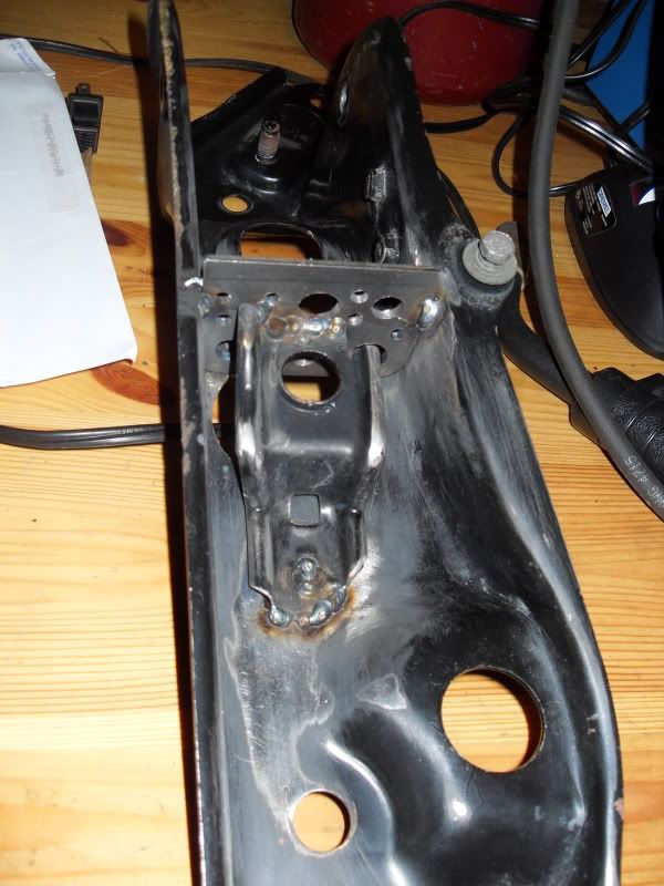
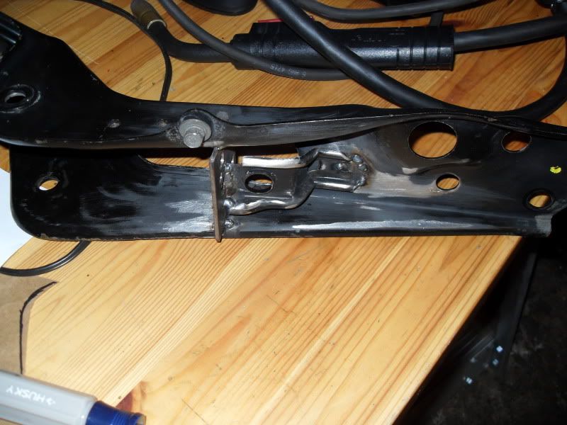
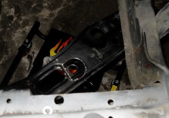
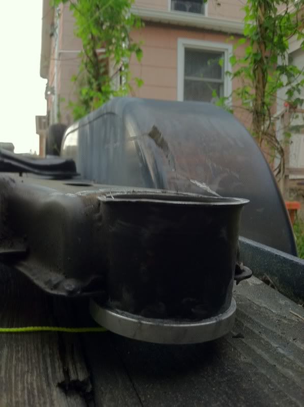
Got a little work done on the rear subframe yesterday. I noticed that even without an upper bushing in the front frame attachment points, that the subframe was contacting the car frame on the lip around the tube/cup that used to house the stock bushings (where everyone puts the collars). I still want to raise the rear roll center a bit, so raising the front of the subframe with no upper bushing makes sense. But raising the whole subframe up for a little free roll center correction is a massive bonus. The cup lip sits about 6mm higher than the rest of the subframe.
The stock subframe bushings sit about 10mm higher than the cups in the rear and about 15mm in front. I've reduced that to about 2 mm in the rear and -6 in the front now for a total roll center correction of ~15mm (8mmR and 21mmF)!. That's like installing drop knuckles! Even if it is less than an inch.
Stock S13 bushing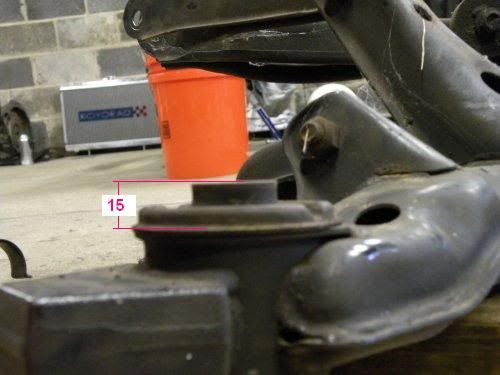
My front S14 subframe less stock bushing but pre hackery. Notice the ~6mm step to the top of the cup even without a bushing.
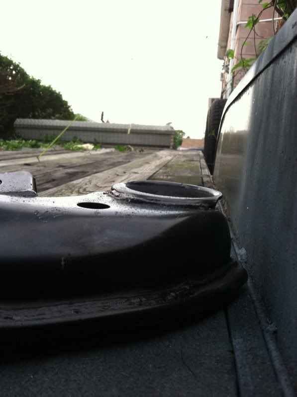
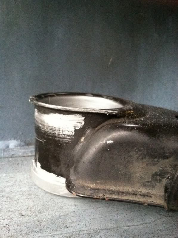
Post Grinding. I'll probably throw a bead in there to make up for what I took off.
The stock subframe bushings sit about 10mm higher than the cups in the rear and about 15mm in front. I've reduced that to about 2 mm in the rear and -6 in the front now for a total roll center correction of ~15mm (8mmR and 21mmF)!. That's like installing drop knuckles! Even if it is less than an inch.
Stock S13 bushing
My front S14 subframe less stock bushing but pre hackery. Notice the ~6mm step to the top of the cup even without a bushing.
Post Grinding. I'll probably throw a bead in there to make up for what I took off.
08-27-2011, 02:21 PM
#214
Staging Lane
iTrader: (5)

Join Date: Apr 2008
Location: Norman, OK
Posts: 80
Likes: 0
Received 0 Likes
on
0 Posts

Any idea on how you are mounting the cell back there? I've got 15 gallon Fuel Safe Enduro in mine, with full cage around it tied in near the rear most subframe mounting points. I could post up or send you some pics if you would like.
08-27-2011, 02:29 PM
#215
I plan on using 1" square tubing to tie the frame rails together where the trunk used to be. I'll space the tubing to perfectly fit the cell. Then I'll use 1" strapping to secure the bottom and top. I've read that strapping has a little more give, and is less likely to puncture the tank than tubing in the event of a serious crash. Plus it's a little lighter than tubing and easier to work with!
08-27-2011, 03:37 PM
#216
Staging Lane
iTrader: (5)
Join Date: Apr 2008
Location: Norman, OK
Posts: 80
Likes: 0
Received 0 Likes
on
0 Posts
Sounds very similar to my setup, but mine is all square tubing. I can't tell from your pictures, have you removed all the speaker tray area by the back window? I found it much easier to build the rear firewall with it gone. I also had to end up replacing the stock 240 filler tube and cap with a 2.25" fuel safe setup. The stock Nissan one was something like 1.6".
08-27-2011, 04:22 PM
#217
Sounds very similar to my setup, but mine is all square tubing. I can't tell from your pictures, have you removed all the speaker tray area by the back window? I found it much easier to build the rear firewall with it gone. I also had to end up replacing the stock 240 filler tube and cap with a 2.25" fuel safe setup. The stock Nissan one was something like 1.6".
I'm trying to both get the fuel cell as low as possible (for CG) and still maximize the diffuser. If you have 1" square tubing between your fuel cell bottom and diffuser than that's one more inch you could have lowered 170 lbs of fuel!
 11-25-2012, 09:07 PM
#219
-12 AN is the standard line used with dry sump set ups. It's damn big and hard to work with. But I read that some Nascar teams run -16 AN to pick up a small amount of horsepower. It makes sense. All automotive oil pumps are crank driven, and pushing oil around under pressure aint easy. For the straigh section of piping under the car (close to 12 feet) I'm planning on using -16 solid stainless line, and then stepping down to -12 for the flexible line.
But if stepping from huge -12 line to even more rediculous -16 is worth some horsepower (and probably better oil pressure) imagine what removing some very sharp 90 degree bends would do. I have to get the oil out of the block and back for both the oil cooler and filter.
Count the number of 90 degree bends the oil has to take inside the block and stock fuel filter to get from the output of the LS1 oil pump to the back main galley...
I count 10!
The internal oil galleys of the LS1 are created by drilling out the block. Most of the bores go all the way through the block, and then the access sites are blocked with screw in plugs. Here's a pic of the two bore sites for the main galleys (at the corner of the block). The front bore gets blocked by the timing chain cover, but the threaded galley port (on the driver side of the block) gets a 16mmx1.5 plug that should probaby have a crush washer under it.
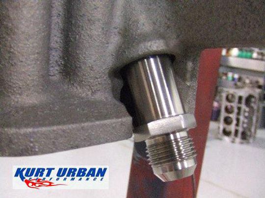
Kurt Urban makes an adapter to tap into the block, here's a pick of it in place of the semi-verticle galley plug at the driver side rear of the block. It has the weird 16mmx1.5mm thread on one end and a -10 AN on the other, custom machined from stainless (but it's $100)
There's also this
Summit Racing Part Number:FRA-460616
Fitting Size 1:-6 AN
Fitting Size 2:16mm x 1.5
(only $3.95)
But here's my problem with both of them.
Internal Oil galley ID: 0.571"mm
Fragola -6 ID: 0.375"
16mmx1.5mm thread minor diameter: 0.577" = 0.377" to 0.422" bore?
Let's presume that Kurt Urban's part only has a wall thickness of 0.100" inside the 16mm thread, that would mean that the bore is only 0.377"
I really don't want to add another restriction. I consider the internal oil galley diameter to be a minimum.
It's a little scary, but right now I'm planning on drilling the two plug ports in the block for a 1/2" NPT fitting. 1/2" NPT female threads first require drilling a 23/32 bore (0.71875"), and then tapping 0.5337" deep for thread engagement.
In Hot Rod's September 2012 issue they did a comparison of -6 AN fittings(0.375 OD), and the inner bores varied from 0.220" to 0.270". Hopefully this means a -12 AN to 1/2" NPT fitting will have an ID somewhere around 0.595" (finally bigger than the stock oil galley dimensions.
I've looked the block over pretty carefully and I think there is plenty of meat for the boring and tapping of the 1/2" NPT. Maybe it would be easier to weld a fitting onto the block, but I worry about messing up any heat treating that was done.
With this external oil routing, I count 10x 90 degree turns that I get to eliminate between the stock LS1 oil pump and the main verticle oil galley at the back of the block! I'll probably introduce 3 or 4 of my own (externally), but all of mine will be WAY more gentle, and that's still a hell of an improvement. Less pressure loss should mean that I can run thinner oil. 0w-20 here I come.
But if stepping from huge -12 line to even more rediculous -16 is worth some horsepower (and probably better oil pressure) imagine what removing some very sharp 90 degree bends would do. I have to get the oil out of the block and back for both the oil cooler and filter.
Count the number of 90 degree bends the oil has to take inside the block and stock fuel filter to get from the output of the LS1 oil pump to the back main galley...
I count 10!
The internal oil galleys of the LS1 are created by drilling out the block. Most of the bores go all the way through the block, and then the access sites are blocked with screw in plugs. Here's a pic of the two bore sites for the main galleys (at the corner of the block). The front bore gets blocked by the timing chain cover, but the threaded galley port (on the driver side of the block) gets a 16mmx1.5 plug that should probaby have a crush washer under it.
Kurt Urban makes an adapter to tap into the block, here's a pick of it in place of the semi-verticle galley plug at the driver side rear of the block. It has the weird 16mmx1.5mm thread on one end and a -10 AN on the other, custom machined from stainless (but it's $100)
There's also this
Summit Racing Part Number:FRA-460616
Fitting Size 1:-6 AN
Fitting Size 2:16mm x 1.5
(only $3.95)
But here's my problem with both of them.
Internal Oil galley ID: 0.571"mm
Fragola -6 ID: 0.375"
16mmx1.5mm thread minor diameter: 0.577" = 0.377" to 0.422" bore?
Let's presume that Kurt Urban's part only has a wall thickness of 0.100" inside the 16mm thread, that would mean that the bore is only 0.377"
I really don't want to add another restriction. I consider the internal oil galley diameter to be a minimum.
It's a little scary, but right now I'm planning on drilling the two plug ports in the block for a 1/2" NPT fitting. 1/2" NPT female threads first require drilling a 23/32 bore (0.71875"), and then tapping 0.5337" deep for thread engagement.
In Hot Rod's September 2012 issue they did a comparison of -6 AN fittings(0.375 OD), and the inner bores varied from 0.220" to 0.270". Hopefully this means a -12 AN to 1/2" NPT fitting will have an ID somewhere around 0.595" (finally bigger than the stock oil galley dimensions.
I've looked the block over pretty carefully and I think there is plenty of meat for the boring and tapping of the 1/2" NPT. Maybe it would be easier to weld a fitting onto the block, but I worry about messing up any heat treating that was done.
With this external oil routing, I count 10x 90 degree turns that I get to eliminate between the stock LS1 oil pump and the main verticle oil galley at the back of the block! I'll probably introduce 3 or 4 of my own (externally), but all of mine will be WAY more gentle, and that's still a hell of an improvement. Less pressure loss should mean that I can run thinner oil. 0w-20 here I come.
03-03-2013, 04:49 PM
#220
I'm using pipe max software to help me calculate my header dimensions for a 4" stroked LS2, with hand ported LS3 heads with a cam some where around 236/240 on 112 +1. But Pipe Max requires an estimate of VE to make the calculation. The exhaust will basically be running open collectors, and I'm presuming the ~15 degrees of overlap at 0.050" should be enough to get me over 100% VE. There are quite a few combos out there similar to mine putting down close to 500 whp. That's got to be 575-600 at the crank. Presuming a max rpm of 7000-7200 that's ~110% VE correct?
I'm posting this in the PCM section because I figure a lot of you guys tune your fuel by VE, and I'm wondering what your highest VE cells are?
Thank a ton!
I'm posting this in the PCM section because I figure a lot of you guys tune your fuel by VE, and I'm wondering what your highest VE cells are?
Thank a ton!