

nissan 240sx (S14) with Modded GTO pan (tons of pics)

 10-23-2009, 02:33 PM
#142
Bunch of little stuff lately. I've been trying to do projects that don't cost any cash, but then my argon/CO2 tank went dry and I spent $40 bucks on bolts a bit more on cut off wheels and a nibbler. Later C note...
It's crazy how many hours these little projects suck up!
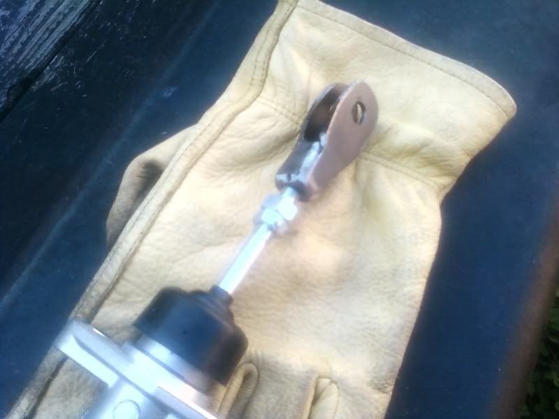
I'm using the same .75" willwood master as everybody else, but I lost the nissans original so I couldn't swap over the original clevis. I fabed up my own clevis by welding steel stap to two sides of a coupling nut. The clutch pedal has a very strange size hole for the original clevis, its close to 9mm or 11/32". I didn't want to just drill it out because it has a thin steel bearing type insert. So I turned my drill press into a make shift lathe and filed down a shaft bolt. Turned out great.
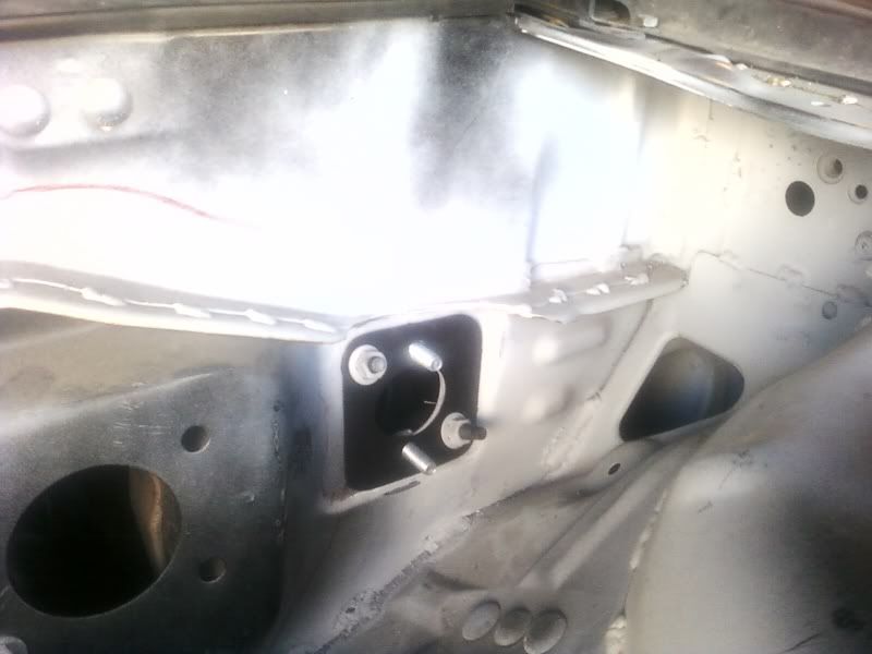
I don't think that these plates are really necessary, but I made one anyway.
On one of the silviav8 forums I saw that some guy manufactured a bunch of plates like this but with studs to make this a true bolt on affair. But the fire wall is doubled at the MC and the force is pushing towards the firewall so I don't think that the plate is necessary. It did make a nice template for drilling holes though. On the inside of the fire wall I welded square bolts for the willwood directly to the firewall, so that I don't need a second person to tighten the nuts/bolts from the engine compartment.
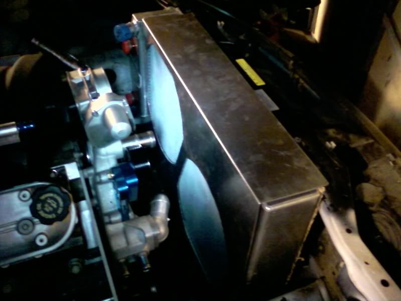
a little shroud work
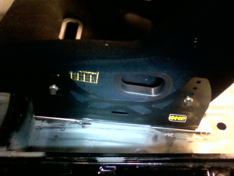
Stillllllll working on my crazy ramp/flat floor seat mount platforms
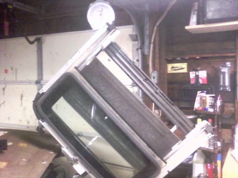
I've agonized over tearing out the sunroof since I bought the car. No going back now! I'm going to see if I can't talk my uncle in Florida into pulling a mold off this thing and making a couple out of carbon fiber. Mike at cognition made one for his time attack S14, but then the mold broke when he pulled the first piece
My Weights and Measures Division, NIST calibrated harbor frieght scale said 25lbs... At least! I'm glad it's gone, even if it is one more thing to do. 25 lbs feels heavier than it sounds if that makes any sense.
It's crazy how many hours these little projects suck up!
I'm using the same .75" willwood master as everybody else, but I lost the nissans original so I couldn't swap over the original clevis. I fabed up my own clevis by welding steel stap to two sides of a coupling nut. The clutch pedal has a very strange size hole for the original clevis, its close to 9mm or 11/32". I didn't want to just drill it out because it has a thin steel bearing type insert. So I turned my drill press into a make shift lathe and filed down a shaft bolt. Turned out great.
I don't think that these plates are really necessary, but I made one anyway.
On one of the silviav8 forums I saw that some guy manufactured a bunch of plates like this but with studs to make this a true bolt on affair. But the fire wall is doubled at the MC and the force is pushing towards the firewall so I don't think that the plate is necessary. It did make a nice template for drilling holes though. On the inside of the fire wall I welded square bolts for the willwood directly to the firewall, so that I don't need a second person to tighten the nuts/bolts from the engine compartment.
a little shroud work
Stillllllll working on my crazy ramp/flat floor seat mount platforms
I've agonized over tearing out the sunroof since I bought the car. No going back now! I'm going to see if I can't talk my uncle in Florida into pulling a mold off this thing and making a couple out of carbon fiber. Mike at cognition made one for his time attack S14, but then the mold broke when he pulled the first piece
My Weights and Measures Division, NIST calibrated harbor frieght scale said 25lbs... At least! I'm glad it's gone, even if it is one more thing to do. 25 lbs feels heavier than it sounds if that makes any sense.
10-24-2009, 01:14 PM
#143
Launching!
iTrader: (1)

Join Date: Feb 2006
Location: Hillaird/Jacksonville Florida
Posts: 200
Likes: 0
Received 0 Likes
on
0 Posts

Well I just read this whole thread and where as I don't understand half of it you really have done some awesome work. Looking forward to seeing this beast finished. Keep up the good work, good luck
01-17-2010, 08:06 PM
#144
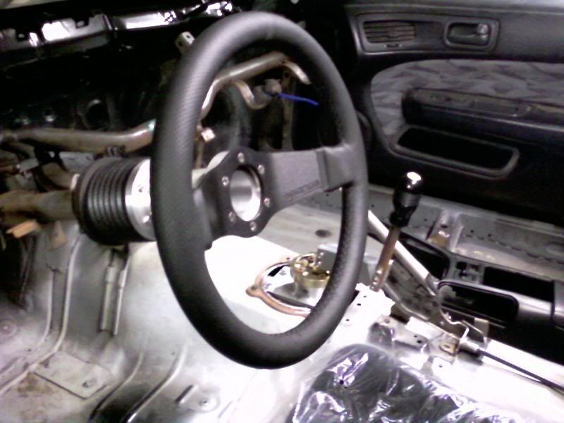
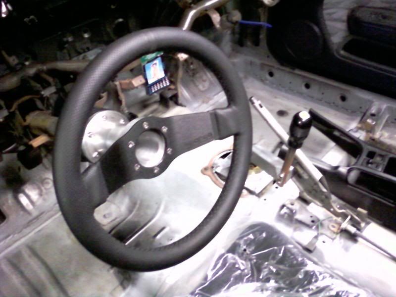
I've been working on correcting the ergonomics since I've moved the seat so far back. Sparco makes the longest 6 hole steering wheel spacer that I could find, but its less than 3 inches. I needed the steering wheel moved back 4.75" to get it where I wanted it. I had access to a lathe, and with a bunch of help from my stepfather Tony, we made this:
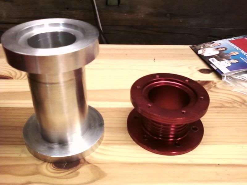
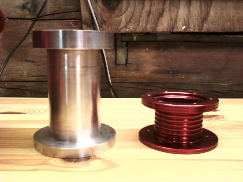
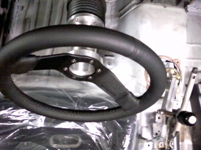
I doubled the thickness of the sparco flanges, and the main pipe wall is about 0.25". I still need to drill and tap a few holes, and make it pretty...
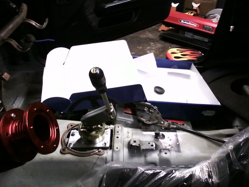
I also wanted to move the shifter location back 4.5", towards the driver 2.5", and up 1.5". Using some clever angles we were able to mill a simple piece of 1x2 billet. It took about 12 hours of machine time to make both pieces.
3rd gear
4th gear
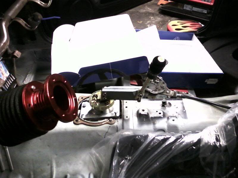
Next, the brake and clutch pedal need to get moved out about 3", and I need to make a mounting platform for the drive by wire pedal. Good times!
I doubled the thickness of the sparco flanges, and the main pipe wall is about 0.25". I still need to drill and tap a few holes, and make it pretty...
I also wanted to move the shifter location back 4.5", towards the driver 2.5", and up 1.5". Using some clever angles we were able to mill a simple piece of 1x2 billet. It took about 12 hours of machine time to make both pieces.
3rd gear
4th gear
Next, the brake and clutch pedal need to get moved out about 3", and I need to make a mounting platform for the drive by wire pedal. Good times!
02-12-2010, 01:49 PM
#145
Slow but sure!
I don't know why it took me so long to catch on, but I've spent WAY too many hours over here the last two days:
http://nissanroadracing.com/
I'm in wuv.
I finally got my harbor frieght metric tap kit in the mail so that I could finish my steering wheel spacer. I had to go to grainger to find a 4.2 mm drill bit for the 5mmx0.8 thread tap though. And after all the trouble the cheap *** tap made some crappy loose "like swishing your dick in the atlantic" loose threads. Sorry it's a translation from an old Japanese insult book that my friend and I used to bust up over. Who would have thought? Cheap taps make shitty threads? It works well enough though:
I also scored this for a a good deal here on Ls1tech from davidws6, it's supposed to be good to 1000 hp. I later found a guy with a turbo LS1 in a malibu or chevell or somthing that was having problems with this pump and pressure changes. He switched to an Aeromotive, but with FPRs and turbos, I'm not going to jump to conclusions and hold anything against it. Besides this retails for more than $429 and the aeromotive is >$500! This is also 100% rebuildable to like new and is supposed to be very reliable for the street and increadibly quiet.
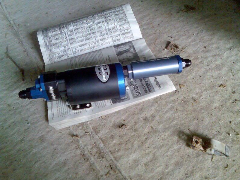
While I'm getting crazy with pics... I just can't figure out the best way to seal up the rear. This looks promising, but I want a REAL seal. No smoke, exhaust, spilled gas fumes, nuttn! You'd probably have to take out the glass for this one. Any other ideas? Post some pics!
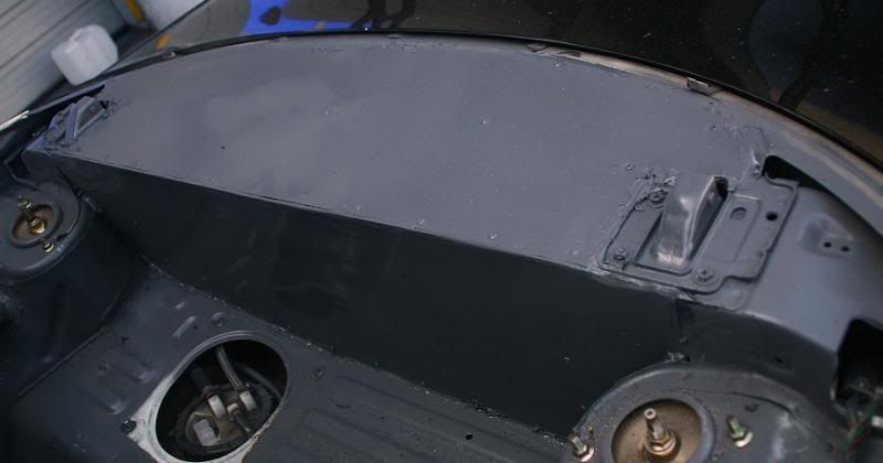
Thanx for following along!
I don't know why it took me so long to catch on, but I've spent WAY too many hours over here the last two days:
http://nissanroadracing.com/
I'm in wuv.
I finally got my harbor frieght metric tap kit in the mail so that I could finish my steering wheel spacer. I had to go to grainger to find a 4.2 mm drill bit for the 5mmx0.8 thread tap though. And after all the trouble the cheap *** tap made some crappy loose "like swishing your dick in the atlantic" loose threads. Sorry it's a translation from an old Japanese insult book that my friend and I used to bust up over. Who would have thought? Cheap taps make shitty threads? It works well enough though:
I also scored this for a a good deal here on Ls1tech from davidws6, it's supposed to be good to 1000 hp. I later found a guy with a turbo LS1 in a malibu or chevell or somthing that was having problems with this pump and pressure changes. He switched to an Aeromotive, but with FPRs and turbos, I'm not going to jump to conclusions and hold anything against it. Besides this retails for more than $429 and the aeromotive is >$500! This is also 100% rebuildable to like new and is supposed to be very reliable for the street and increadibly quiet.
While I'm getting crazy with pics... I just can't figure out the best way to seal up the rear. This looks promising, but I want a REAL seal. No smoke, exhaust, spilled gas fumes, nuttn! You'd probably have to take out the glass for this one. Any other ideas? Post some pics!
Thanx for following along!
 02-17-2010, 09:10 AM
#147
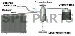
I had a long conversation with the tech guys at C&R radiator yesterday about how to plumb my nascar style radiator. Here's a couple things I learned.
1) Originally I was worried about the top being the input of the radiator because I was afraid it would push the air into the system. But there is a -4 port at the top of the radiator. Ideally this would be -6 and on the top/opposite side of the input. This port basically has the same function as the steam vents on top of the LSx heads: to allow air/steam to exit to the top of the surge tank.
2) The bottom of the surge tank should be connected with a -10 (but -8 will work) to the lowest point of the radiator near the radiators outlet. This recirculation line is supposed to help prevent pump cavitation.
3) Don't completely fill the surge tank. The air above the water in the surge tank acts like an air spring against expansions in the coolant.
4) I don't know how legal this would be in most classes of racing, but circle track guys sometime run the the overflow hose to spay on the windshiled instead of in a bottle. That'll get your attention!
I also had some interesting conversations with Magnafuel and Lonie at http://www.lonniesperformance.com in Perryopolis, PA. I had heard of guys running pumps capable of more than 700 hp would re-circulate so much fuel at cruise that the fuel vaporlocks. Lonnie's solution is dual in-tank walbros triggered by a hobs swithch on boosted apps, and by both an rpm and full throttle switch. Magnafuel reccomended against fuel speed controllers, as their pumps weren't designed to run under 12.5 volts. They said that the one time they heard of their pumps vaprolocking it was fixed with a fuel cooler. I'm probably going to install a fuel cooler under the car.
02-17-2010, 06:44 PM
#148
I was originally going to reuse the stock powersteering reservoir, but I found this on ebay for $35 and figured it would be easier to hook up with its AN fittings, and that the extra volume and filter couldn't hurt. I think these were originally designed for off road race cars, I got it from a buggy shop.
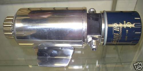
I also read a cool article about slowing down the LS1 powersteering pumps. It can help reduce overheating, overboosted feel, and can be worth 1-3 hp.
http://www.gmhightechperformance.com...all/index.html
http://www.turnone-steering.com/ls1.html
The pumps are blueprinted and I would use their universal pump which can be oriented in any direction and has -6 outlet, -10 inlet. With billet wheel it costs about $300. I called turn one and asked about their recommendation on using a PS cooler. I would prefer to not use one as it's just more places for leaks to occur. They said to plumb it up without one, and then to use an IR thermometer after a hard track run. As long as the temp is < 275 F you're golden, no cooler needed. If not...
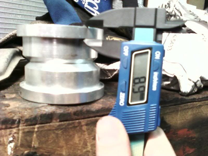
I've been getting confused as to which fittings I have already, and which ones I need to order. I found this chart which I blew up and printed. I like to laminate cool/usefull **** (like the LS1 engine torque settings tables) and post 'em in my garage. Here's the cool AN ferrule indentification chart:
I found the following posted on the nissan road racing forum:
"Power Steering
Oil Pump Relief hydraulic pressure - 1,390 - 1,484 PSI
Fluid Capacity - Approx. 1 L
High Pressure
> PS Pump Banjo Fitting = 16mm Banjo
> High Pressure Steering Rack Fitting = M14x1.25 inverted flare
> PS pressure Sensor = M12x1.25
Low Pressure
> Low Pressure Hose OD = 3/8"
> Reservoir Host OD = 5/8"
> PS Pump Return fitting OD =1/2"
> Rack Return Fitting OD = M14x1.25 inverted flare"
Should help me to make the right hoses. If anyone can verify or correct the above it would be MOST appreciated!
I also read a cool article about slowing down the LS1 powersteering pumps. It can help reduce overheating, overboosted feel, and can be worth 1-3 hp.
http://www.gmhightechperformance.com...all/index.html
http://www.turnone-steering.com/ls1.html
The pumps are blueprinted and I would use their universal pump which can be oriented in any direction and has -6 outlet, -10 inlet. With billet wheel it costs about $300. I called turn one and asked about their recommendation on using a PS cooler. I would prefer to not use one as it's just more places for leaks to occur. They said to plumb it up without one, and then to use an IR thermometer after a hard track run. As long as the temp is < 275 F you're golden, no cooler needed. If not...
I've been getting confused as to which fittings I have already, and which ones I need to order. I found this chart which I blew up and printed. I like to laminate cool/usefull **** (like the LS1 engine torque settings tables) and post 'em in my garage. Here's the cool AN ferrule indentification chart:
I found the following posted on the nissan road racing forum:
"Power Steering
Oil Pump Relief hydraulic pressure - 1,390 - 1,484 PSI
Fluid Capacity - Approx. 1 L
High Pressure
> PS Pump Banjo Fitting = 16mm Banjo
> High Pressure Steering Rack Fitting = M14x1.25 inverted flare
> PS pressure Sensor = M12x1.25
Low Pressure
> Low Pressure Hose OD = 3/8"
> Reservoir Host OD = 5/8"
> PS Pump Return fitting OD =1/2"
> Rack Return Fitting OD = M14x1.25 inverted flare"
Should help me to make the right hoses. If anyone can verify or correct the above it would be MOST appreciated!
02-20-2010, 10:53 AM
#149
What is the first thing that hits and stops/limits bump travel?
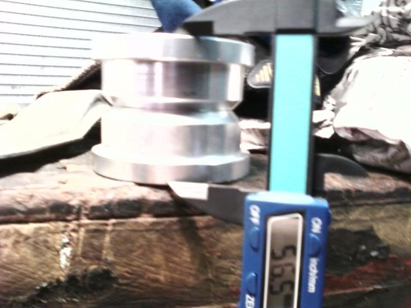
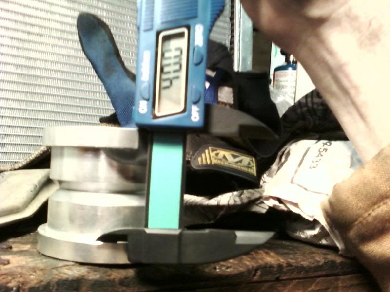
I started working on the rear subframe yesterday. I have the ebay solid subframe bushings. I measured the stock bushings and they sit somewhere between 12.6 and 13.6 mm above the subframe. SPL wasn't kidding when they said that you can raise your subframe half an inch! It's like a free drop spindle mod! But my cheapo ebay bushings have a 9mm lip above the subframe . So here are my options.
1. Buy SPL bushings and use their shims to get back the squat that raising the subframe gives up.
This cost more $, but still a very fair price.
2. Use only the bottom half of the ebay bushings
I worry that there would be too much stess on the bolts that hold the subframe with the top half of the bolt unsupported.
3. Machine off the lip of the ebay bushings.
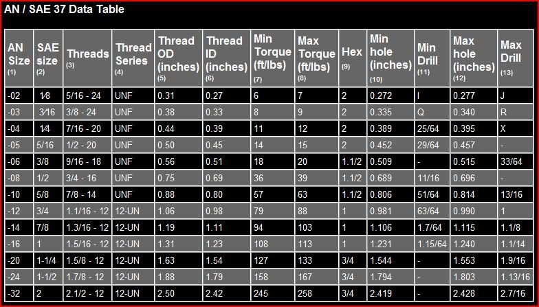
This is complicated. If I machine the 9 mm lip off from the side, and drop the whole top bushings into the subframe-cylinder it will not fill the cylinder to the top. The cylinders in the subframe are 56.5 mm tall. Here's how that measures up to the ebay bushings
The lip
from SCC:
"...Unlike the front of the car, small amounts of anti-squat are generally a good thing for a rear-drive car since it allows for softer rear suspensions without the excess squat.
Cars like the Nissan R32 Skyline GT-R, Z32 300ZX and S13 240SX have a great deal of anti-squat in their rear suspension geometry. This makes them transition to on-throttle oversteer very rapidly because anti-squat, like anti-dive, significantly increases the wheel rate. This is why the S13 works so well for drifting.
Extreme anti-squat can cause wheelspin and rear wheel hop under power, which is why the Z32 is notorious for launching poorly at the dragstrip.
Rear-wheel-drive drag racers have made a science of anti-squat tuning to maximize rear-wheel traction. Drag cars often have so much anti-squat geometry that the back of the car actually lifts when launching, driving the tires into the ground. Drag cars have adjustable four-link rear suspensions,so this percentage is tunable for the amount of bite desired in different conditions (see sidebar on page 102 to learn how to calculate anti-lift, anti-dive and anti-squat)."
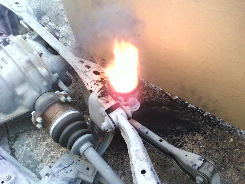
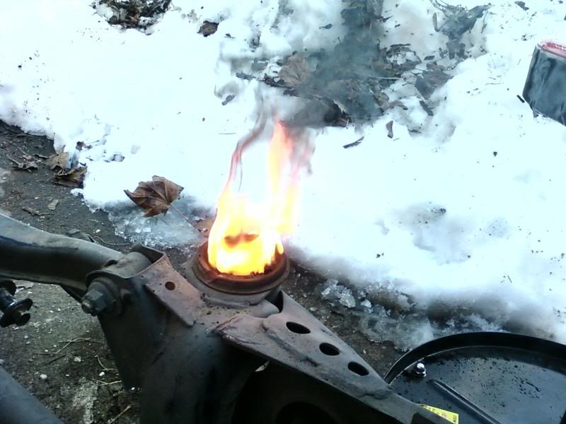
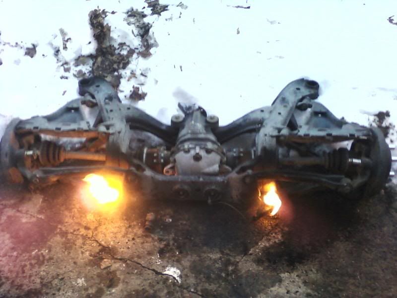
Fun with fire
Tuning with anit-squat (here's my understanding):
More anti-squat: More predictable handling/transition to on-throttle oversteer. Allows softer springs.
Less anit-squat: More rear weight transfer, and better launch. Requires stiffer springs.
I started working on the rear subframe yesterday. I have the ebay solid subframe bushings. I measured the stock bushings and they sit somewhere between 12.6 and 13.6 mm above the subframe. SPL wasn't kidding when they said that you can raise your subframe half an inch! It's like a free drop spindle mod! But my cheapo ebay bushings have a 9mm lip above the subframe
. So here are my options.1. Buy SPL bushings and use their shims to get back the squat that raising the subframe gives up.
This cost more $, but still a very fair price.
2. Use only the bottom half of the ebay bushings
I worry that there would be too much stess on the bolts that hold the subframe with the top half of the bolt unsupported.
3. Machine off the lip of the ebay bushings.
This is complicated. If I machine the 9 mm lip off from the side, and drop the whole top bushings into the subframe-cylinder it will not fill the cylinder to the top. The cylinders in the subframe are 56.5 mm tall. Here's how that measures up to the ebay bushings
The lip
from SCC:
"...Unlike the front of the car, small amounts of anti-squat are generally a good thing for a rear-drive car since it allows for softer rear suspensions without the excess squat.
Cars like the Nissan R32 Skyline GT-R, Z32 300ZX and S13 240SX have a great deal of anti-squat in their rear suspension geometry. This makes them transition to on-throttle oversteer very rapidly because anti-squat, like anti-dive, significantly increases the wheel rate. This is why the S13 works so well for drifting.
Extreme anti-squat can cause wheelspin and rear wheel hop under power, which is why the Z32 is notorious for launching poorly at the dragstrip.
Rear-wheel-drive drag racers have made a science of anti-squat tuning to maximize rear-wheel traction. Drag cars often have so much anti-squat geometry that the back of the car actually lifts when launching, driving the tires into the ground. Drag cars have adjustable four-link rear suspensions,so this percentage is tunable for the amount of bite desired in different conditions (see sidebar on page 102 to learn how to calculate anti-lift, anti-dive and anti-squat)."
Fun with fire
Tuning with anit-squat (here's my understanding):
More anti-squat: More predictable handling/transition to on-throttle oversteer. Allows softer springs.
Less anit-squat: More rear weight transfer, and better launch. Requires stiffer springs.
02-20-2010, 11:08 AM
#150
from SPL:
For their subframe spacers:
For maximum squat (eg. drag racing), rotate the instant center down by installing large diameter spacers above front subframe bushings and small diameter spacers below rear subframe bushings.
For slightly increased squat, lower the instant center by installing spacers above all subframe bushings.
For slightly increased anti-squat, raise the instant center by installing spacers below all subframe bushings.
For maximum anti-squat (eg. drift), rotate the instant center up by installing small diameter spacers below front subframe bushing and large diameter spacers above rear subframe bushings.
For their solid bushings
Our CNC machined T6061 aluminum subframe bushings completely replace the stock bushings to eliminate free play of the subframe relative to the chassis, reducing wheel hop and improving suspension performance. Our new version 2 solid subframe bushings is designed to allow the subframe to sit up to 1/2" closer to the chassis (raising the subframe), which will allow up to 1/2" compensation of roll center for a lowered car.
However raising the subframe will not just change roll center, it will also increase anti-squat. Therefore our subframe bushings include 1/4" slide in shims so you can quickly raise or lower the subframe in minutes, and adjust the roll center and anti-squat behavior to best fit your driving style! Our unique adjustable subframe bushings offer a completely new way to tune the suspension behavior.
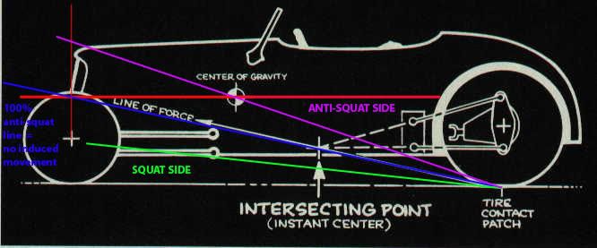
from www.formulaindyracing.com
Chassis engineers talk about "anti-squat" at the rear on acceleration and use a traditional diagram to calculate "percentage of anti-squat" (see illustration next page). Because the weight (center of gravity) of a typical road car is supported by the front and rear wheels, engineers draw a "100-percent anti-squat" force line from the rear tire contact patch to the front wheel vertical center-line, at the height of the center of gravity. If the actual "line of force" for the car – the line from the rear tire contact patch through the instant center of the rear suspension – coincides with the 100-percent anti-squat line, then theoretically the rear suspension will neither lift nor drop, and the rear of the car will not rise or squat, as the car accelerates. That is, if the instant center of the rear suspension lies anywhere on this line, the car will have 100-percent anti-squat. If the instant center is anywhere below the line, the rear will squat (or, have a certain percentage – a fraction – of anti-squat). If the instant center is above this line, it will have more than 100-percent anti-squat, which means the rear of the car will be pushed upwards by the suspension links as the car accelerates.
Last edited by GIGAPUNK; 02-21-2010 at 07:54 PM.
02-21-2010, 03:00 PM
#151
On The Tree
iTrader: (3)
Join Date: Jun 2006
Location: Westminster, MD
Posts: 164
Likes: 0
Received 0 Likes
on
0 Posts
I have the SPL bushings which I was planning to drop the subframe today but just got my initial motor set-in today. Are you going to do the SPL bushings? If so, I would be interested in what height you plan to use.
02-21-2010, 10:22 PM
#152
I updated the pic in the last post. Should make it a little easier to understand where you'd have to put SPL's spacers to get the effect you want.
If I hadn't bought the ebay bushings ages ago I'd get the SPL bushings. But I'm going to machine down the rear ebay bushings to no lip and epoxy them in flush, and in the front I'll machine the 9mm lip down to 4mm. This should give me even more squat than factory. And would be the equivalent to about half the thickness of one of SPLs spacers.
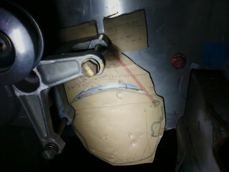
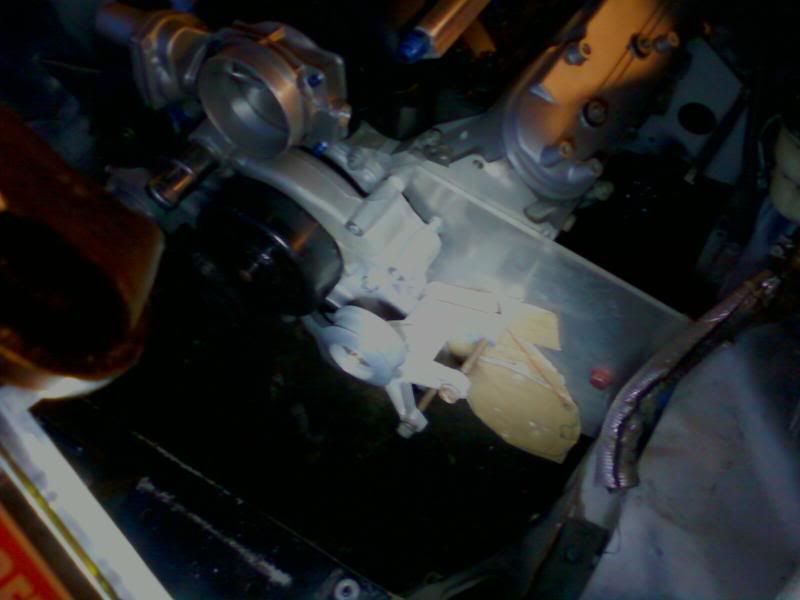
I could never understand why the corvette had the alternator placed so high. I weighed my GTO alternator today, and it was 14 lbs!!! I have an F-body alternator bracket that will not fit a GTO alternator which has wider mounting boses. I plan on using only the botom mounting holes of the F-body bracket and lowering the alternator to almost the level of the bottom of the crossmember with heim joints and rod.
Red line will be the heim and hex
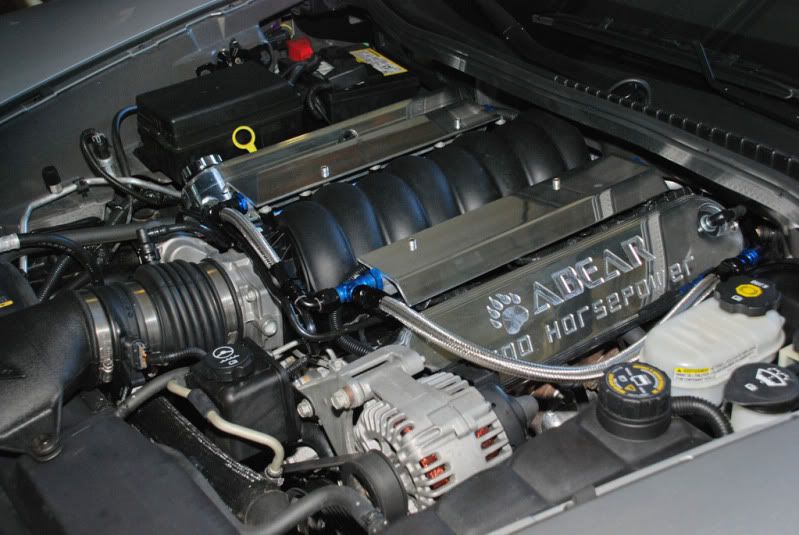
The corvette's alternator is actually above the head. That must be almost 2 feet higher, and 14 lbs!
stock vette placement
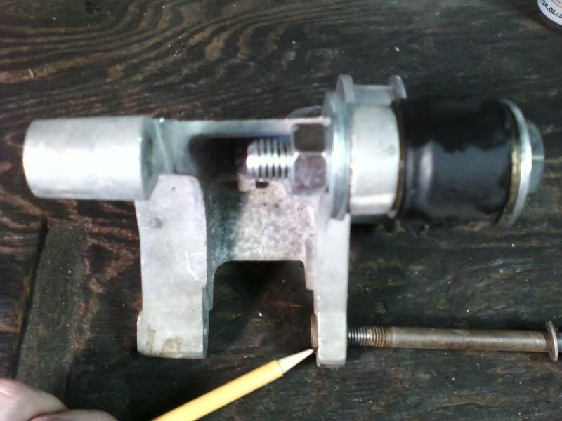
The old subframe bushings finally came in handy. I removed the metal cylinder from the center of the bushings and cut one in half so I could push the steel alternator bracket liner (marked with pencil) flush with the inside, so that the F-body bracket will be wide enough for the GTO alternator.
I could never understand why the corvette had the alternator placed so high. I weighed my GTO alternator today, and it was 14 lbs!!! I have an F-body alternator bracket that will not fit a GTO alternator which has wider mounting boses. I plan on using only the botom mounting holes of the F-body bracket and lowering the alternator to almost the level of the bottom of the crossmember with heim joints and rod.
Red line will be the heim and hex
The corvette's alternator is actually above the head. That must be almost 2 feet higher, and 14 lbs!
stock vette placement
The old subframe bushings finally came in handy. I removed the metal cylinder from the center of the bushings and cut one in half so I could push the steel alternator bracket liner (marked with pencil) flush with the inside, so that the F-body bracket will be wide enough for the GTO alternator.
02-22-2010, 02:53 PM
#154
Teching In

Join Date: Jul 2008
Location: Los Angeles ,Ca
Posts: 7
Likes: 0
Received 0 Likes
on
0 Posts
I like the k-member mods you did. this is the only modified k-member
I have seen that looks like it is as strong if not stronger than the original design.
I went the rear sum option and cut the firewall to sit the motor back a few inches. My pan sits behind the rack.
I like the attention to detail you have put in. could only imagine the hours spent doing online research.
I am on my first, mine is a street machine that will get some track time and mountain driving.
here is my buildhttp://forums.nicoclub.com/zerothread/342129
02-22-2010, 03:39 PM
#155
I like the k-member mods you did. this is the only modified k-member
I have seen that looks like it is as strong if not stronger than the original design.
I went the rear sum option and cut the firewall to sit the motor back a few inches. My pan sits behind the rack.
I like the attention to detail you have put in. could only imagine the hours spent doing online research.
I am on my first, mine is a street machine that will get some track time and mountain driving.
here is my buildhttp://forums.nicoclub.com/zerothread/342129
I have seen that looks like it is as strong if not stronger than the original design.
I went the rear sum option and cut the firewall to sit the motor back a few inches. My pan sits behind the rack.
I like the attention to detail you have put in. could only imagine the hours spent doing online research.
I am on my first, mine is a street machine that will get some track time and mountain driving.
here is my buildhttp://forums.nicoclub.com/zerothread/342129
02-23-2010, 01:27 AM
#156
Teching In
Join Date: Jul 2008
Location: Los Angeles ,Ca
Posts: 7
Likes: 0
Received 0 Likes
on
0 Posts
thanks.
i am going to rebuild a portion of strut bar
since I am converting to TPI intake
it is a few inches lower so the brace that goes across is going to get pushed forward a few inches to be closer to the actual shock towers(more support).
have not had it corner weighted. want to though.
for now I tried to balance everything I could.
turbo replaced battery in front(sits directly over frame rail.)
power steering and alternator on opposite side of the turbo.
battery is between rear shock towers.
my RCI 17 gallon fuel cell is a little off center towards passenger side to make room for the exhaust to exit stock location. but it is a 4 in exhaust from turbo back so it has a bit of weight it self.
hard to work with the oval tubing to make suddle angle changes. a lot of time heating with torch and hammering to alter shape and making measurements and odd cuts.
here is a vid of my car before I got a lot of issues resolved.
never mind the commentary, did not know what the hell i was talking about and my clutch was not full disengaging.
http://www.youtube.com/watch?v=aDX5VXxcyGw
Last edited by 550sx!; 02-23-2010 at 01:36 AM.
02-23-2010, 08:19 AM
#157
damn dude. Your so smart it scares me.. Seriously crazy about the thought process, well done. A ton of good information here.. especially the dry sump talk.. must have spent 6hrs reading and re-reading this post and others linked from it. Good **** bro, keep at it.
02-24-2010, 10:53 AM
#158
I called wegner motorsports about a 1/2" water pump spacer. They had two sets of 0.520" in stock at only $14 each!
[Recall I'm running a .25" motorplate and a corvette waterpump that is made to sit 0.75" behind the the camaro acc. offset I'm using. = 0.50" to make up @ the WP.]
I may have to knock them down a bit on the mill though. They told me that each WP gasket is about 0.060" thick. A normal application uses one, I'd have to use 3! Wegner suggested that I might be able to get away with just silicone and no gaskets. What do you guys think? It's all flat aluminum on aluminum. If I want to use all of the gaskets a perfect offset for the spacers ould be 4.880".
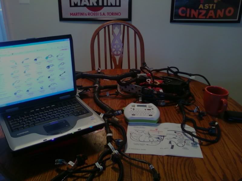
I've also started to label my wiring harness. It's a used harness I got off ebay a while back from a 2006 GTO. It was missing the interior harness and throttle pedal so I had speartech make me the extension harness for the GTO gas pedal I have. I'm struggling figuring out a few of the connectors. Does anyone know where I can get a wiring diagram with the wire colors for free?
I've figured most of it out just by looking at the connectors here:
http://www.eficonnection.com/eficonn..._pigtails.aspx
Thanx for the Christmas label maker Mom!
 02-24-2010, 11:31 AM
#159
On The Tree
iTrader: (3)
Join Date: Jun 2006
Location: Westminster, MD
Posts: 164
Likes: 0
Received 0 Likes
on
0 Posts
Personally, I would go with the gaskets as you will probably not save much in terms of space with the silicone and it will probably be easier to disassemble/reassemble in the future.