When you click on links to various merchants on this site and make a purchase, this can result in this site earning a commission. Affiliate programs and affiliations include, but are not limited to, the eBay Partner Network.
Well you can also add me to the list of those saying that you don't need the 2" primaries. With the larger primaries you will lose a little bit of torque and port velocity. 2" primaries belong on strictly a race car. Rich
Bologna. He is big inch and supercharged. He will lose nothing and gain everything. I run 2" Hedmans on my nitrous motor and run 11.2 at 122 on motor. And I drive it everyday. It will pay off when I run a 250hp nitrous shot on it.
Any reccomendation on some 2 in primaries headers for the g body?
Hedman makes a nice multi-piece 2" primary head. I've run them for about a year and like them a lot. The unpainted steel ones are reasonably priced. Only a minor dent on passenger side and drivers side interfered with my 4l80e's long shift shaft.
Bologna. He is big inch and supercharged. He will lose nothing and gain everything. I run 2" Hedmans on my nitrous motor and run 11.2 at 122 on motor. And I drive it everyday. It will pay off when I run a 250hp nitrous shot on it.
For an NA application with no Nitrous a 2" header is WAY too big unless you're in the 450+" NA club.....my 700+RWHP NA LS7 runs with a 1-7/8" triple step header! Trust me, after having one of the best header designers in the Country design my headers I think if he could have squeaked a few more ponies with a 2" header he would have but he didnn't! Enough bench racing for today LOL!
I like the BRP mounts due to them raising the engine higher than the plates everyone sells. Also don't like how the plates use the factory clamshells. BRP mount lets the musclecar pan clear no problem. When I did my swap only headers available were the BRP unless you wanted to modify Pacesetter f body ones which I did and they didnt work so I bought the crazy expensive BRPs.
If I was going to do it again, I'd use BRP mounts with either a Holley pan or the gmpp musclecar pan, and then buy a set of speed engineering stainless headers made for a first gen f body and see how they fit. My ceramic coated brps are rusting already. Been about 4-5 years now and its disappointing.
Getting ready to order my mounts. Still trying to find out if the truck accessories and intake work with the BRP mounts. I Like the fact that these mounts will set the engine higher, just worried about the other stuff.
Anyone have experience using these mounts with the truck intake and accessories? What about exhaust manifolds?
With the full Holley set up, mounts, oil pan, headers etc, the alt barely cleared the hood on my 83 cutlass. I can't see it clearing with the brp mounts. The truck intake is tall, so I don't imagine it will clear either. The Holley stuff is the way to go on a g body in my opinion.
Getting ready to order my mounts. Still trying to find out if the truck accessories and intake work with the BRP mounts. I Like the fact that these mounts will set the engine higher, just worried about the other stuff.
Anyone have experience using these mounts with the truck intake and accessories? What about exhaust manifolds?
Raising the engine will worsen your U-joint working angles and complicate the fitment of any transmission other than a legacy GM automatic such as a TH350, TH400 or 2004R.
Anybody done any frame strengthening to the gbody? I'm not going nuts with my swap, I want around 400 horsepower and I'd like the car to handle it too. I realize the car was made for a 305, but is frame strengthening really necessary?
.
I see you have a Monte Carlo SS. If you're not a member on gbodyforum.com you might want to check it out. A lot of good knowledgeable people there . Here is a link that answers your question:
One of the biggest issues with a G body are old deteriorated body mounts. Install a nice set of energy suspension poly mounts and add all the factory stiffening bars and your car will be fine with 400 hp. Grand Prix frame rail bar, Cutlass triangulation bars, etc. For further rigidity I added the GNX Grand National rear seat brace to my ride.
UMI makes some really nice products for chassis stiffening. Here is a link with some of their products
I was a member some time ago, i'll have to try and remember my login. I think somewhere along the line there I was just getting better info from this site and stopped using theirs.
I'll check out UMI. I was looking at hotchkis about going tubular, then I was gonna just grab some nos body mounts, mine have seen better days. Whats the advantage of the poly mounts?
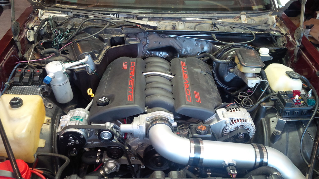
Forget if it was asked in here where people are mounting ecms, figured id share. Been working on it for about 8 hours total, fitting dash, welding bracket, throwing bracket away, making new bracket, etc.
I made a bracket to mount mine behind the coolant overflow tank on the inner fender well. Mine uses the small E67 ECM. I made another bracket to mount the fuse box on the other side. I'm using the GMPP harness/controller kit.
I'll check out UMI. I was gonna just grab some nos body mounts, mine have seen better days. Whats the advantage of the poly mounts?
Thanks by the way
Not all of the NOS body mounts are available any more. The advantage of Poly is higher stiffness, better materials and better design less prone to rusting. Even the performance VIN 9 G body mounts were soft. Some guys use Delrin (UHMWPE) solid mounts but Poly doesn't squeak and in my opinion is the best product.
Alright here is the solution for the key lock-out (aka NSS)/reverse light issue with using the stock column range rod and the Hooker swap headers.
1. The bracket which mounts on the brake distribution block needs to have the ball socket moved up 1/2". I cut it along the bend and rewelded it - make sure you measure the angle first before cutting;
2. The bracket on the transmission selector switch need to be cut and moved up 1/2". Note you will need a nut that does not have an integrated washer due to the reduced threads to draw down against (and yes, you could weld the brackets together too);
3. The cross shaft which translates the movement from the shifter/transmission selector switch to the column lock-out needs to be straightened and shaped to go over the header. Guess how much clearance you need to add? That's right - 1/2"! I used a vice and a BFH to give it that sweet custom reverse banana bend;
4. The pinch nut which goes to the column rod needs to flipped to the other side of the bracket on the cross shaft. I rounded the edges off of it to reduce the risk of it binding on things; and
5. Lastly, you may find that you want to chop an inch or two off of the cross shaft that inserts into the ball socket. I took close to 2" off and ran a shorter spring. This really aided in assembly with the header in the way. You may also find that you want to chop an inch off of the bottom of the column rod - your results may vary. Measure once, cut once, weld once, measure again, and cut again.
I am running a B&M shifter and a 4L60E which may be wider at the case body location for the transmission selector switch than other GM transmissions.
I've been lurking this forum for awhile and got a lot of good information. I have a 1983 El Camino, originally with the 229ci and I've swapped a 2001 5.3L from a suburban into it with a 4L80E.
I'm having some issues/confusion with the wiring. I got it started a few weeks ago, but have since rethought the wiring and am still a little unsure about how this is correctly done. I'm using the fusebox that's shown on LS1Tech.
When I got it started, I had the below three red wires (PCM, Lights, Fuel Pump/Starter) all combined and sent directly to the battery. I only have these labeled that way because that's what i've identified them as powering through trial and error.
I thought that seemed a little odd, so I then tried starting it with all of those sent to KEY ON (pink wire to the ignition), except the PCM wire. I tried a few variations of that, but the only way it worked was with all going directly to Battery. With the exception of the PCM, all red wires are coming from the original El Camino wiring.
There's one additional red wire that I've marked alternator indicator. this originally went to a connector that also had a brown wire. I believe that powers the alternator indicator at the dash.
Any advice on how these wires should be ran, or what in general I should do to figure this out? Maybe i'm just over thinking it and they all go to battery?


 02-23-2017, 12:25 AM