
RX7/forged 370/TC78
 09-25-2013, 09:54 PM
#201

i dont notice too much a difference on the street, but i dont drive on highways faster than about 65 usually
it def was funny with it so quiet driving down camping at the track and not making a sound and people watching after they saw what it ran haha


 10-12-2013, 09:15 PM
#204
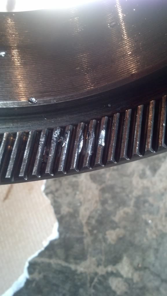
Ok so just a little deal about the powerglide, I chipped some teeth last pass of track day, it was a stock 1.76 gearset
here is what it looked like, not bad at all
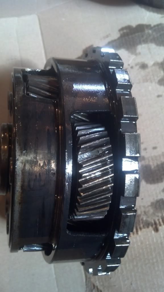
just take you through some stuff for those never been in a glide
first is a roller governor support

here is the reverse gear pack installed into the case, i have 6 clutches here the piston is machined to accept more clutches
for reverse this pack is applied and it locks the planetary ring gear stationary

here is where you check clutch pack clearance, usually shoot for .010 per friction. i have .058 for 6 frictions, just right. different thickness steels and frictions can be used to set clearance as can machining the apply piston

here is the planetary ring gear installed into the clutch pack

here is the aftermarket 1.80 straight cut gearset/carrier/outputshaft vs the stock 1.76

here is the plantary installed into the case, and the input shaft installed showing how it engages the planetary


here is aftermarket sun gear vs the stock, it is installed onto the high clutch drum

here is the high clutch pack, I am running 6 clutches here. the apply piston is machined to accept more clutches if desired. measure pack thickness to set clearance

measure to find pack clearance, again .07-.01 per friction is the norm. different thickness frictions and steels can be used to set this, aswell as piston machining. i have .052 here

the stock high drum is fine to use in high power situations, here is the pack installed into the drum

here is what it looked like, not bad at all


just take you through some stuff for those never been in a glide
first is a roller governor support

here is the reverse gear pack installed into the case, i have 6 clutches here the piston is machined to accept more clutches
for reverse this pack is applied and it locks the planetary ring gear stationary

here is where you check clutch pack clearance, usually shoot for .010 per friction. i have .058 for 6 frictions, just right. different thickness steels and frictions can be used to set clearance as can machining the apply piston

here is the planetary ring gear installed into the clutch pack

here is the aftermarket 1.80 straight cut gearset/carrier/outputshaft vs the stock 1.76

here is the plantary installed into the case, and the input shaft installed showing how it engages the planetary


here is aftermarket sun gear vs the stock, it is installed onto the high clutch drum

here is the high clutch pack, I am running 6 clutches here. the apply piston is machined to accept more clutches if desired. measure pack thickness to set clearance

measure to find pack clearance, again .07-.01 per friction is the norm. different thickness frictions and steels can be used to set this, aswell as piston machining. i have .052 here

the stock high drum is fine to use in high power situations, here is the pack installed into the drum
 10-12-2013, 09:36 PM
#205
here is the high clutch hub. this is an aftermarket unit
the stock one is cast iron and not suitable to high power

here is the hub installed into the high drum/clutch pack

here is the wedding ring and thrust plate installed ontop of the hub

here is the aftermarket sungear/plate installed onto the high drum/clutch assembly
for high gear this clutch is applied which locks the planetary up and every rotates so you get a 1:1 ratio input to output

here is the high drum assembly installed into the planetary/case
input shaft in just to show

here is the pump, just a stocker, i run the stock stator support. i dont run a sprag or diode in the converter so it is easy on the support. simple mods to the pump

i have converted to the pump to a roller thrust bearing, there is no reason to use a washer in a high hp build

pump installed and checking thrust play of unit. this is adjusted in a couple ways. can shim rear bearing, front bearing, machining drum/pump, or different pump gasket thicknesses
with a roller bearing you can keep thrust tight, a washer under in a power build needs quite a bit to last
i am at .007"
most will say .005-.015 with roller, .025 minimum with washer

i forgot to get a pic of the band assembly but for low gear the band is applied which locks the high clutch drum and utilizes the planetary gearing, 1.80 in this case
this is a hardened band adjusting strut/bolt. good idea

this is a billet band apply servo and cover, the cover is just for looks, the piston is functional as it has two sealing rings vs 1 of stock

here is the band assembly installed looking from the bottom

BTE transbrake valve body installed

and you are done, JW bell and sfi sheild.

hope that sheds some light on a powerglide for those who have never been in one
10-13-2013, 05:48 AM
#206

That should be pretty much bullet proof now.
This is wayne from norotors. The guy that did the IRS swap that everyone said not to do lol
Im doing the ls thing now. I'm doing a 5.3 with a s480. Im hoping to pick up a second over the sbc on spray. Anyways your car looks nice. Good luck with the new trans. Im sure faster times to come!
This is wayne from norotors. The guy that did the IRS swap that everyone said not to do lol
Im doing the ls thing now. I'm doing a 5.3 with a s480. Im hoping to pick up a second over the sbc on spray. Anyways your car looks nice. Good luck with the new trans. Im sure faster times to come!
 10-14-2013, 08:59 AM
#208
That should be pretty much bullet proof now.
This is wayne from norotors. The guy that did the IRS swap that everyone said not to do lol
Im doing the ls thing now. I'm doing a 5.3 with a s480. Im hoping to pick up a second over the sbc on spray. Anyways your car looks nice. Good luck with the new trans. Im sure faster times to come!
This is wayne from norotors. The guy that did the IRS swap that everyone said not to do lol
Im doing the ls thing now. I'm doing a 5.3 with a s480. Im hoping to pick up a second over the sbc on spray. Anyways your car looks nice. Good luck with the new trans. Im sure faster times to come!
you will enjoy the LS, good motors


 12-31-2013, 06:33 PM
#218
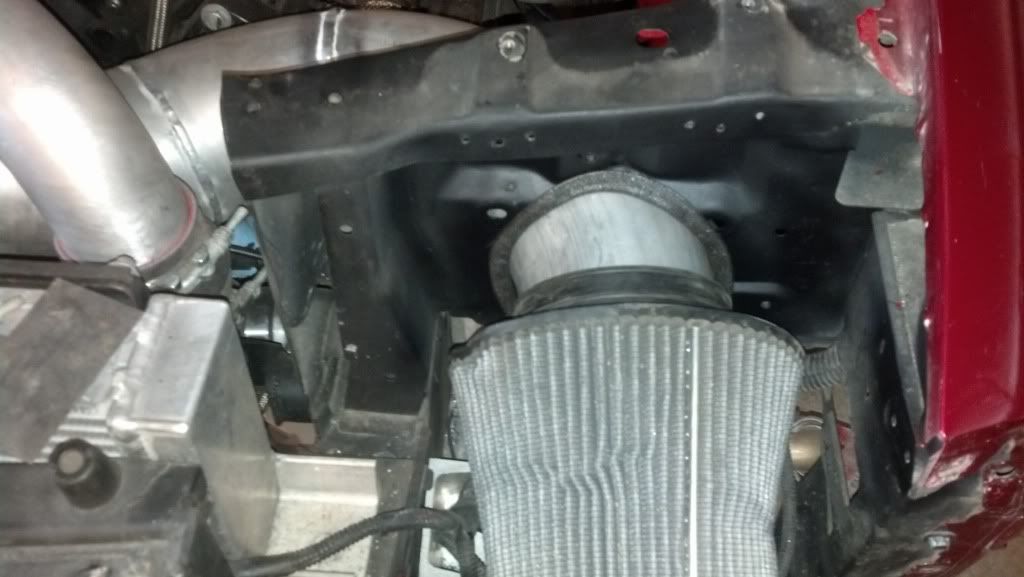
so i wondered why my steering rack was starting to kiss the oil pan, investigated
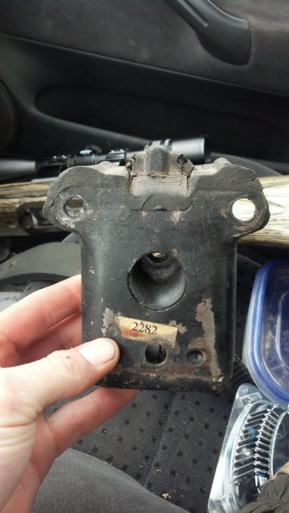
the napa rubber mounts where getting *** pounded i guess lol
that hole is supposed to be in the middle, the rubber has just distorted that far
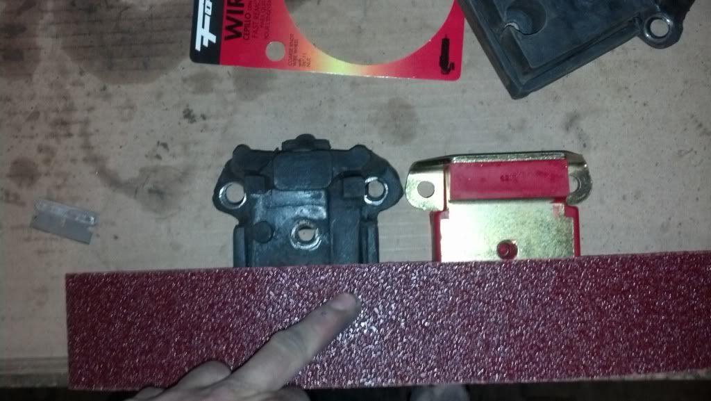
picked up some polys, home vibs are not horrible
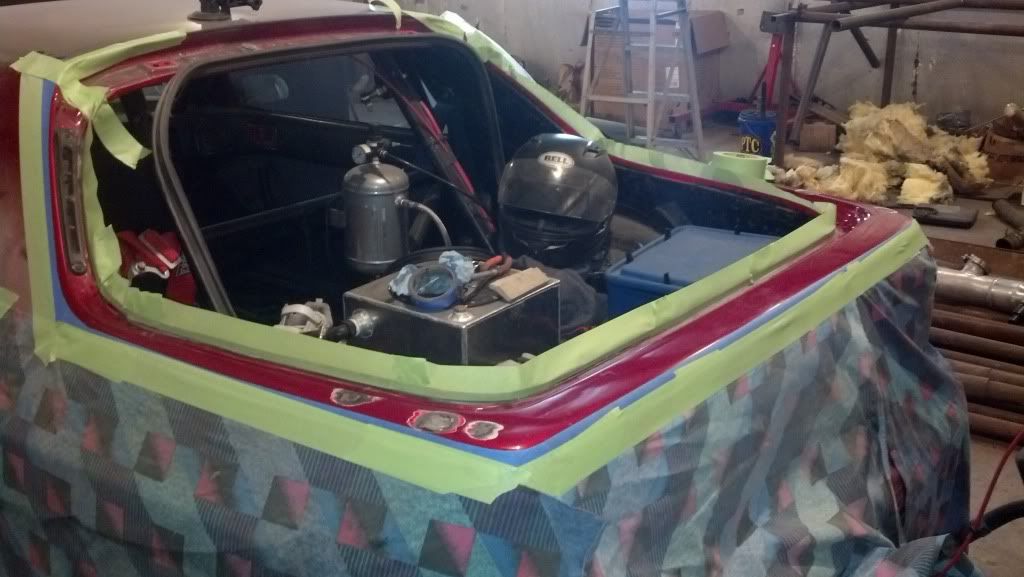
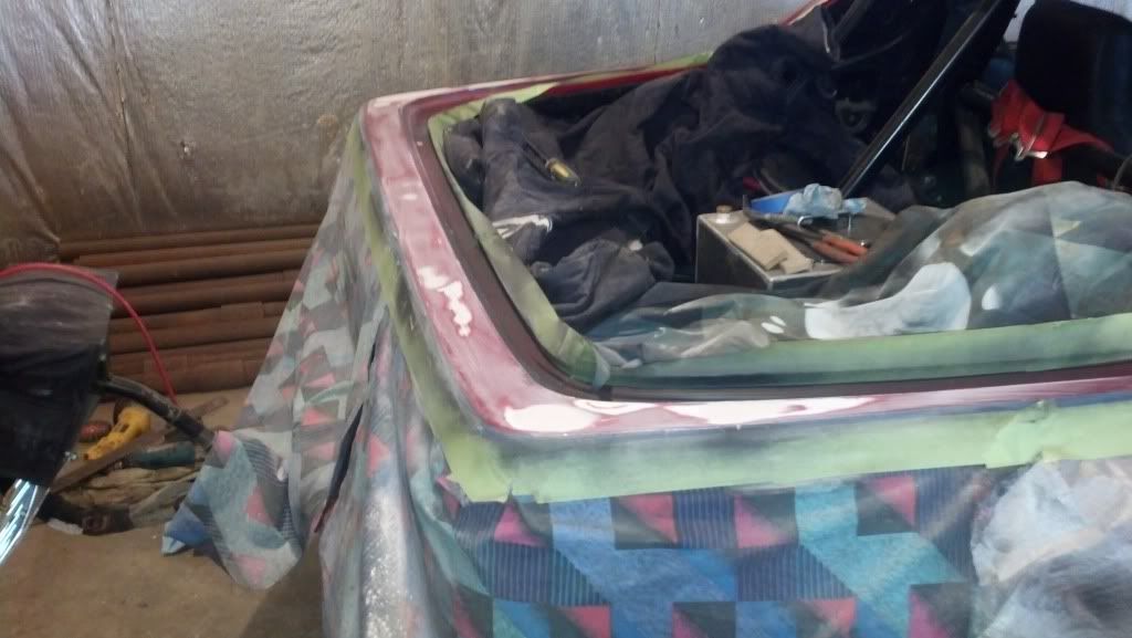
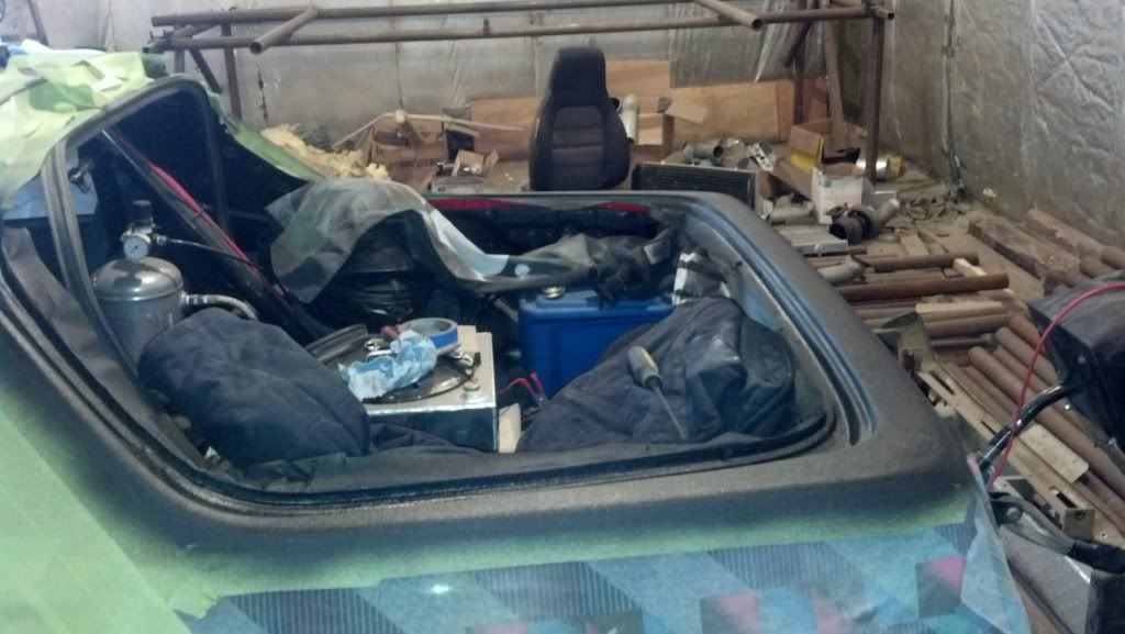
and i tried my first attempt at some body work, very nervous haha
i welded in the holes from the spoiler and the antenna, and there where some dents in the back deck that i have zero idea how they got there, someone sat on it or something
never have used body filler before ever, kinda cool to try something new. not hard to do but man alive it would take some time to resto a complete car that isnt straight as an arrow
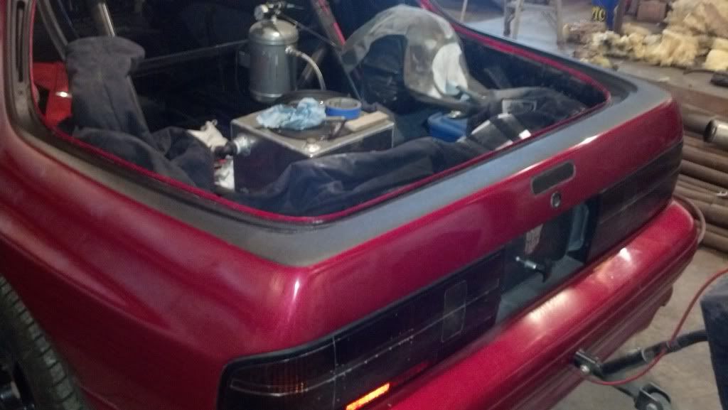
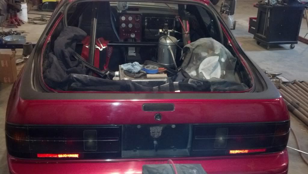
It is a high traffic area in back there (always messing with the water tank and i throw my parachute in back then drive), so being Zac Brown i did my bedliner
i think it turned out dope
the napa rubber mounts where getting *** pounded i guess lol
that hole is supposed to be in the middle, the rubber has just distorted that far
picked up some polys, home vibs are not horrible


and i tried my first attempt at some body work, very nervous haha
i welded in the holes from the spoiler and the antenna, and there where some dents in the back deck that i have zero idea how they got there, someone sat on it or something
never have used body filler before ever, kinda cool to try something new. not hard to do but man alive it would take some time to resto a complete car that isnt straight as an arrow
It is a high traffic area in back there (always messing with the water tank and i throw my parachute in back then drive), so being Zac Brown i did my bedliner
i think it turned out dope


 12-31-2013, 06:33 PM
#219
so i wondered why my steering rack was starting to kiss the oil pan, investigated
the napa rubber mounts where getting *** pounded i guess lol
that hole is supposed to be in the middle, the rubber has just distorted that far
picked up some polys, home vibs are not horrible
and i tried my first attempt at some body work, very nervous haha
i welded in the holes from the spoiler and the antenna, and there where some dents in the back deck that i have zero idea how they got there, someone sat on it or something
never have used body filler before ever, kinda cool to try something new. not hard to do but man alive it would take some time to resto a complete car that isnt straight as an arrow
It is a high traffic area in back there (always messing with the water tank and i throw my parachute in back then drive), so being Zac Brown i did my bedliner
i think it turned out dope
03-01-2014, 09:35 PM
#220
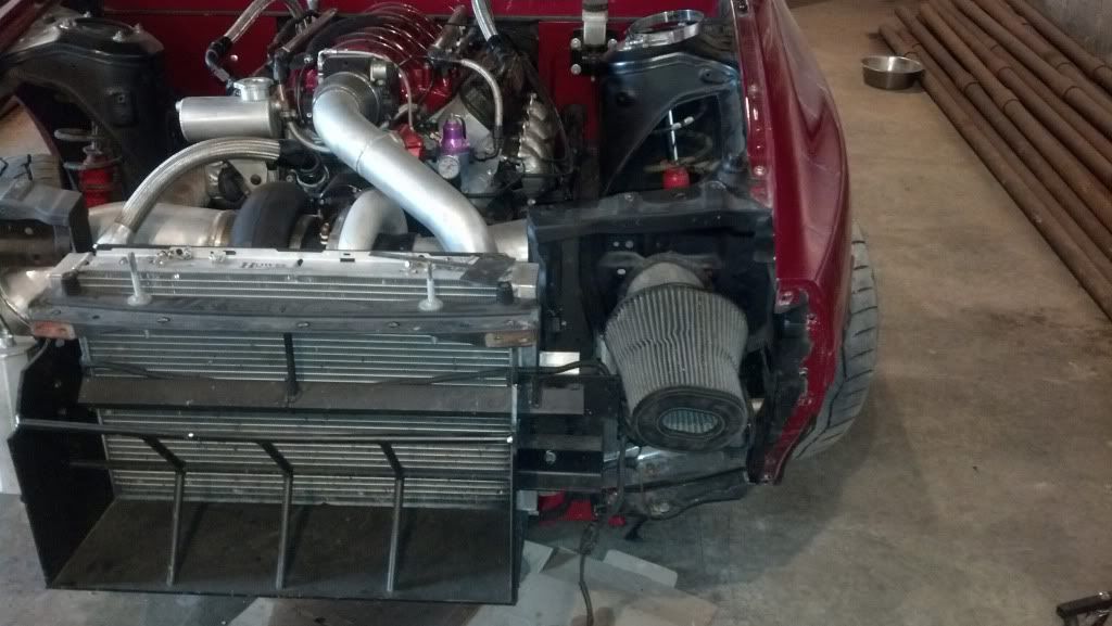
so fixing something i didnt have done proper to begin with
had it sort of ni**er rigged, whole intercooler system is 1" line but i had it stepped down to small 1/2" npt into and out of the intercooler
my cooler is small, to maximize its function i need all the flow capacity through the cooler i can get
i bought a flow meter setup so i can actually witness the change and where i am at
here is how it was setup half assed last year
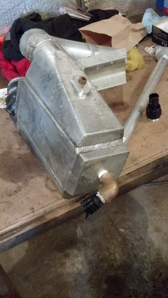
this delivered around 10gpm at 13.5 volts, which surprised me, i didnt think it would be quite that much necked down that far
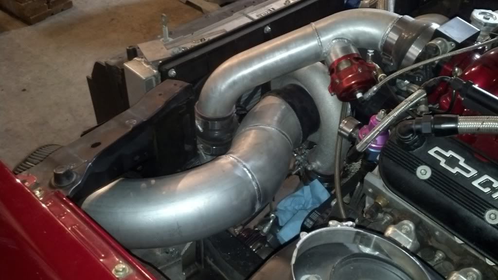
so then we go zac brown on it, some schd 40 aluminum pipe since i didnt like the idea of just making the ports larger on the intercooler since the standoff is very little
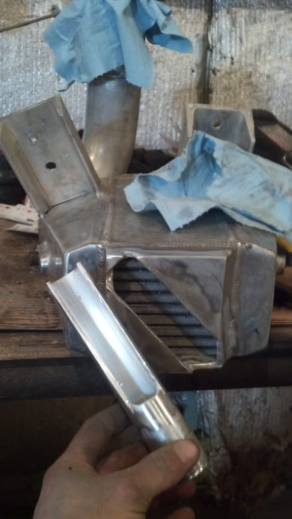
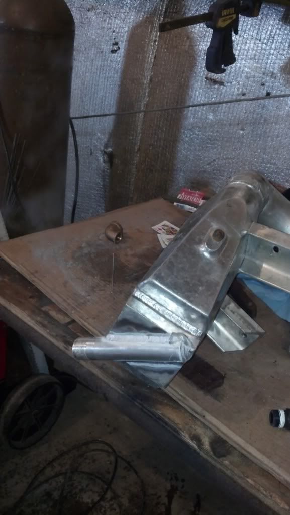
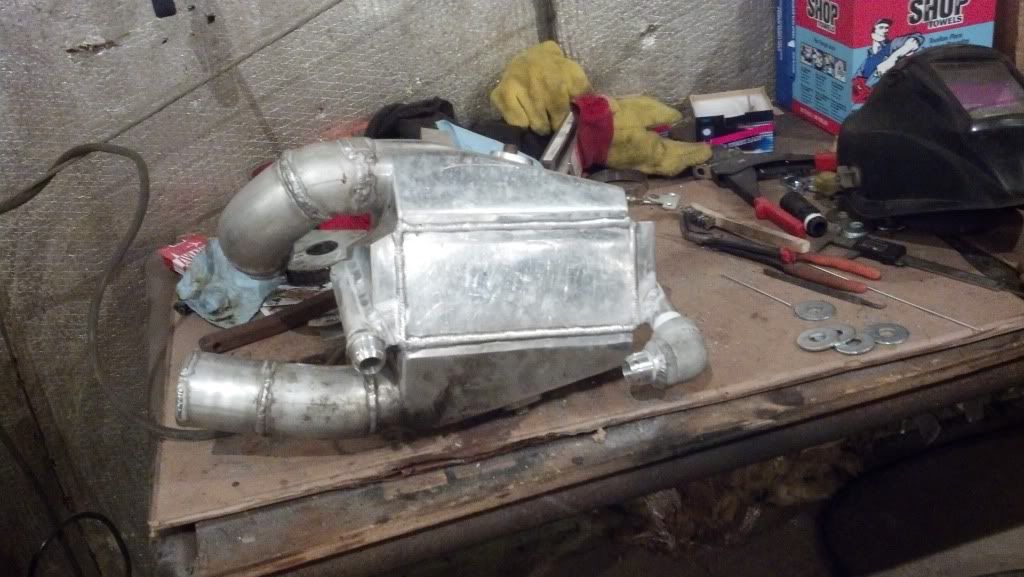
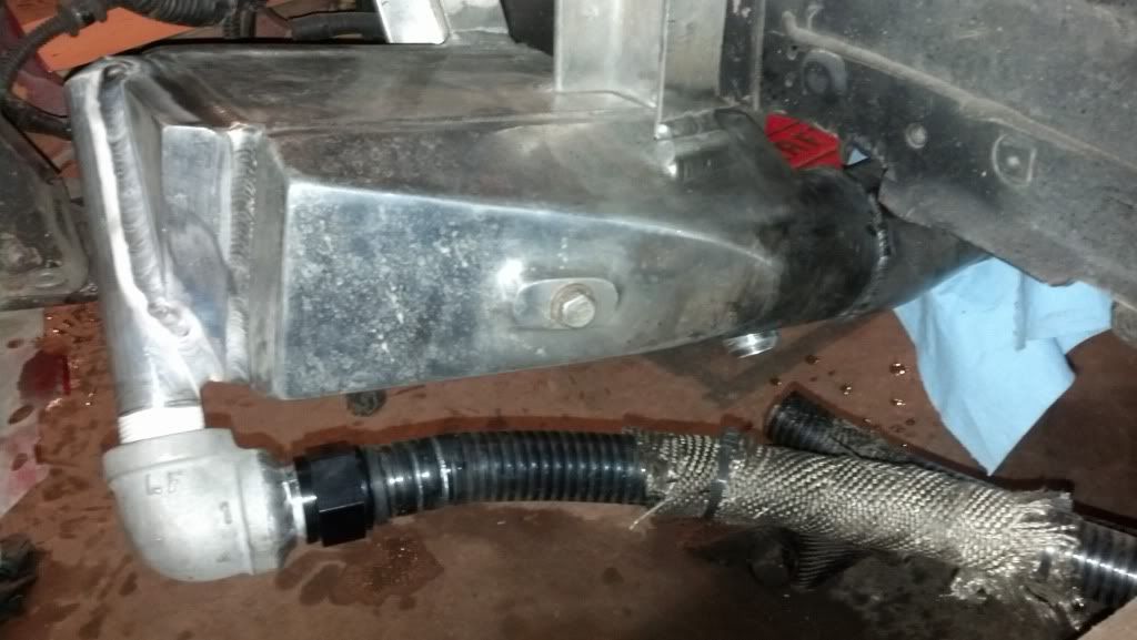
i need a 45* pushlock to for the other side which i dont have so sadly i couldnt do a test to see what my efforts resulted in
i changed to JIC fittings from just poly hose barb stuff
had it sort of ni**er rigged, whole intercooler system is 1" line but i had it stepped down to small 1/2" npt into and out of the intercooler
my cooler is small, to maximize its function i need all the flow capacity through the cooler i can get
i bought a flow meter setup so i can actually witness the change and where i am at
here is how it was setup half assed last year

this delivered around 10gpm at 13.5 volts, which surprised me, i didnt think it would be quite that much necked down that far
so then we go zac brown on it, some schd 40 aluminum pipe since i didnt like the idea of just making the ports larger on the intercooler since the standoff is very little


i need a 45* pushlock to for the other side which i dont have so sadly i couldnt do a test to see what my efforts resulted in
i changed to JIC fittings from just poly hose barb stuff