When you click on links to various merchants on this site and make a purchase, this can result in this site earning a commission. Affiliate programs and affiliations include, but are not limited to, the eBay Partner Network.
Is that the same MAP sensor you used previously? I seem to recall the bolt on sensors have a different connector than the clip on sensors. I know i had to swap connectors on my harness when making the change. Is your harness compatible with the sensor you're using now?
It's an entirely new harness+plug.. old sensor was a 2.5bar sensor off a Cobalt SS, this is a 3bar sensor off of I-forget-what. Totally different plug, but I got a pigtail for it that I'll splice into the Holley wiring, since I need to extend the wiring anyways from the back-top of the manifold to the front...
Little things... like the driveshaft slip yoke. The new T56 Magnum (converted to F-body tailhousing) has the same output shaft length, but 31 spline not the T56 27 spline. Luckily the trans came with an uber nice billet nitrided chromoly slip yoke, which I wanted to try swapping myself. I've never done any U-joint stuff.. so no better time to learn than the present. Before even giving it a go, I measured the old/new yoke dimensions... even tho the new slip yoke is longer overall, it has the same bearing-center-to-shoulder length, and the spline depth is actually broached even closer to the bearing center. I also checked that the new yoke can still insert into the tailhousing up to the output shaft seal... so in theory this slip yoke should fit just fine with the same F-body tailhousing.
If it works, it can't be ghetto right? Last thing I wanted was this driveshaft to get loose and roll around, land on something and get dented...
One of the many helpful things about work's shop.. an abundance of random aluminum slugs and tubes for pushing and receiving...
I managed to push the opposing bearing end cap about 3/4 of the way out (still inserted about 1/8" deep) but it was still in there tight enough to need more than a softblow hammer knock, and I didn't want to start trying to grab onto it with vicegrips...
In order to push out the other side's end cap, I needed a weird contraption to push on the shaft-side yoke instead of poking the 1st end cap back in, undoing the work I just did. So I angled the shaft appropriately and made a C-shaped pushing tool to push...
Which ended up working quite well. Unfortunately it was STILL not quite enough clearance to wiggle the U-joint out of the yoke.
However there was enough gap between the end of the U-joint cross shaft and the inboard end of an endcap for me to make a thin spacer, to then have the cross shaft push the end cap out...
Worked like a charm!....
And used the washer again to easily take the second end cap out of the slip yoke...
Reassembly was super straight forward. The end cap snap rings used in the previous yoke assembled into the new yoke, however they preloaded the bearings just a biiiiiit too much for my liking, so I'm going to try and find some thinner snap rings, maybe 0.055", 0.050", or even 0.045" thick, depending on what's needed to not allow play but have the bearing just slightly slicky...
Wait a minute.....does the spline go all the way through and there is NO plug at the U-joint side? that needs to be plugged or water & dirt will get in the trans and/or fluid will migrate out via the clearance of the splines to the shaft....
Wait a minute.....does the spline go all the way through and there is NO plug at the U-joint side? that needs to be plugged or water & dirt will get in the trans and/or fluid will migrate out via the clearance of the splines to the shaft....
There's definitely a pressed-in cap with a snapring as extra security... you can see it in pic #2 from my last post above ^^
Final decision for driver side turbo drain return to pan... a 45 degree adapter fitting... this will allow me a couple different hard/soft line routing options that I'll evaluate soon...
New McLeod RXT Twin Street clutch! So pretty!....
Using the provided plastic alignment tool for the clutch discs, I thought it was going well and would be easy...
Double checking pressure plate finger depth and comparing to the throwout bearing as installed on the trans...
First snag... the opening/notch on the T56 Magnum wasn't quite big enough for the fitting on the Speedway Motors clutch line, had to go at it with a file, of course...
Clearanced....
For some reason, the plastic 26T alignment tool McLeod provided didn't align the clutch discs well, after 2 attempts I could still feel a step/offset between the splined sections on the discs. The tool inserted pretty tightly into the pilot bearing, but I think as I hung the 1st and then 2nd discs on the tool, the weight of the discs started sagging the tool in the pilot bearing and it wouldn't allow the trans input shaft to insert past the 1st clutch disc.
So, I removed the bellhousing and the throwout bearing and just used the trans itself as the alignment tool, and worked out quite well..
Does anyone on here have recommendations for lifter preload? With the heads torqued down on LS9 gaskets, I measured 7.322" free pushrod length, which is with the rocker touching the valve enough that there is no "up/down" play when I tap or jiggle it, but the rocker can shuttle side-to-side slightly. I have 7.400" pushrods that would produce 0.078" preload if I reused. I have stock lifters, and a 0.615" lift Tick turbo cam. From reading it seems like ~0.050" preload is recommended, which would mean I'd have to get one-step-shorter 7.375" pushrods.
Those plastic clutch alignment tools are mostly junk. As you noted, they don't square the disks against the crank, which results in less than perfect alignment. I use a Quarter Master steel alignment tool and it works very well.
If the engine will come out again, it would be a good idea to add a remote bleeder. If not, next time...LOL
Thanks for that info Jim. My engine is a 2005 gen3 LQ4, still has the stock lifters.... I'm trying to find the P/N on them but having a difficult time.
I just did a little more reading/measuring/math.... my pushrod length checker is a "theoretical" 6.800" when full short, and I measured it as actually 6.816" overall, which lines up well with this older Comp Cams diagram below, showing the relationship between theoretical and actual-measured lengths.
So using that above diagram as a reference, my actual-measured pushrod length was 7.322", remove the ~0.017" to bring that actual measurement to theoretical "gauge length", and the theoretical pushrod length for zero lash zero preload for my setup is 7.305". I confirmed this by counting back the turns from the adjusted correct checker length to full short, which was 10.125 turns. That equates to (6.800")+(10.125)x(0.050") = 7.306".
So if I were to reuse my 7.400" pushrods, they would achieve ~0.095" preload. A 7.350" pushrod length would produce ~0.045" preload, and 7.375" length would produce ~0.070" preload.
I did have a bit of ticking before... I'm wondering since my previous setup also had LS9 gaskets, if I was running that ~0.095" preload with my previous 7.400" pushrods, and that was collapsing the lifters and making the "sewing machine" noise.....
For the wiper motor, I made a bracket to mount it under the cowl, I can't remember if I uploaded a post about that (circa 2015 maybe), but I'll see if I can dig some pics up.
Faster ramps and higher spring rates can do that to the lifters. Your .095" as-calculated preload is too much. 7.375 would be in the sweet spot. Or, knowing you, you can just fab up a set of your own
I'll dig into your thread a bit and see if I can find something. I've seen guys using S-10 Blazer motors, but reusing the stocker would be nice.
After a ton of thread reading, guys seem to favour 0.050"-0.060".. however a few out there are like "bahh I've had my engine up to 7200rpm with 0.100" preload and it's fiiiine"
I'm leaning towards the 7.375" giving 0.070" preload.. as I'm thinking 0.045" preload could just be a touch on the low side... hopefully some other people can chime in soon, I'd like to order new pushrods in the next day or so in order to have them for this coming weekend.
For the hidden wiper motor stuff, I have the backup of all my pics and thread updates on my home computer.. I'll search it tonight to see if I ended up making an update post about the wiper motor. Summary is that I used a motor/lever stock from a 240SX so it has intermittent, however I never ended up retrofitting the lever body into a custom/retro looking dash ****. I just had the 240SX column lever jammed under the driver seat and if I happened to get caught in rain, I would whip it out and plug it into the sub-harness I wired up that is stashed behind the instrument cluster, just under the headlight switch. I re-used the Nissan wiper motor and timing control unit, and wired it so that it really just needs switched 12V, ground, and the control lever connected in order to work.
The wiper motor mounts to the backside of the "cover plate" on the firewall, so it's essentially a bolt-in affair with no weird fabrication needed to the firewall/cowl to get it to fit. I just needed to rejig the linkage a bit for the 240SX motor driving arm. Here's a demo video I remember making:
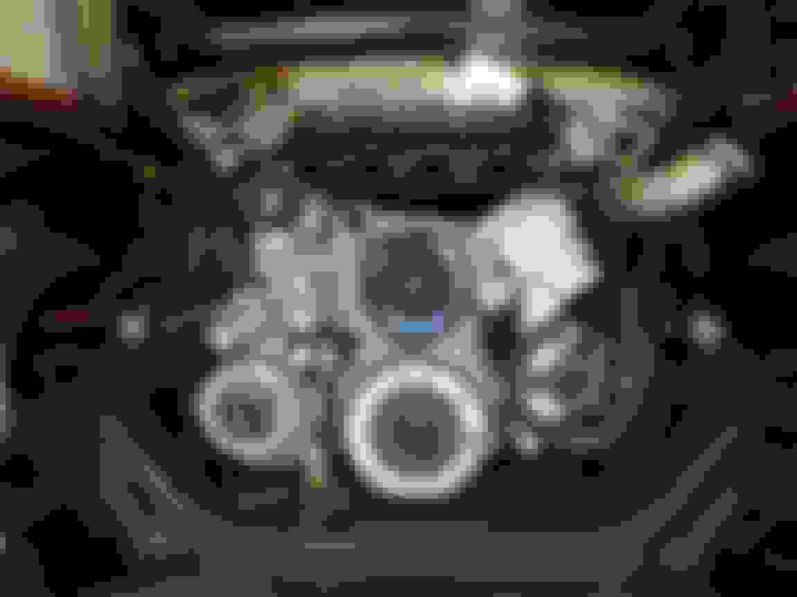
Had another productive weekend, didn't get anything 100% accomplished but I got most of the way thru a handful of things. Tacked together and fit the P/S pump bracket.. it fits well enough that it'll stay on the car...
All the pullies appeared in-plane, that's a good start...
The lip on the smooth plastic idler pulley just to the right of the water neck was just touching, so I'll skim down the offending lip and make it fit...
Drilled some holes and welded on 1/8" NPT bungs for pre-turbo exhaust gas temp and pressure...
For the exhaust pressure sensor, just to try and prolong its life, I thought I'd add a copper coil to dissipate some heat before the sensor...
The exhaust temperature sensor next to it is a K-type thermocouple, good to I think 2000*F, so that won't be an issue.
Because the pressure sensor will now be on the end of this big pigtail spring, I think I'll hard mount the sensor body to the head to help with vibrations.. just need to source a P clip that will work, or maybe machine something....
Jigged some high-precision strapping to align each side's wastegate recirculation pipe to its respective downpipe, to final tack the two parts together...
This just show some of the shrinkage/warpage that occurs when you weld everything together. That being said, since there's probably half a dozen welded joints, 3 flanges, and a gasket added to the whole setup since I last fit-checked it in a tack-welded state, I'm pretty happy how close things lined up, it was no problem to fill the small gap...
Done welding the downpipes! Other than O2 bung and V-band flanges, of course.
Also got the Comp Cam 0.080" 7.375" pushrods in and installed everything.. valvetrain is officially buttoned up!
FYI, they have different diameter idler pulleys, in case you wanted to keep the lip (which is unnecessary unless it's misaligned). I went through a few sizes to get my tensioner in the right place with the belt installed when I did my AC bracket and subsequent belt rerouting.

 05-02-2018, 11:41 AM