When you click on links to various merchants on this site and make a purchase, this can result in this site earning a commission. Affiliate programs and affiliations include, but are not limited to, the eBay Partner Network.
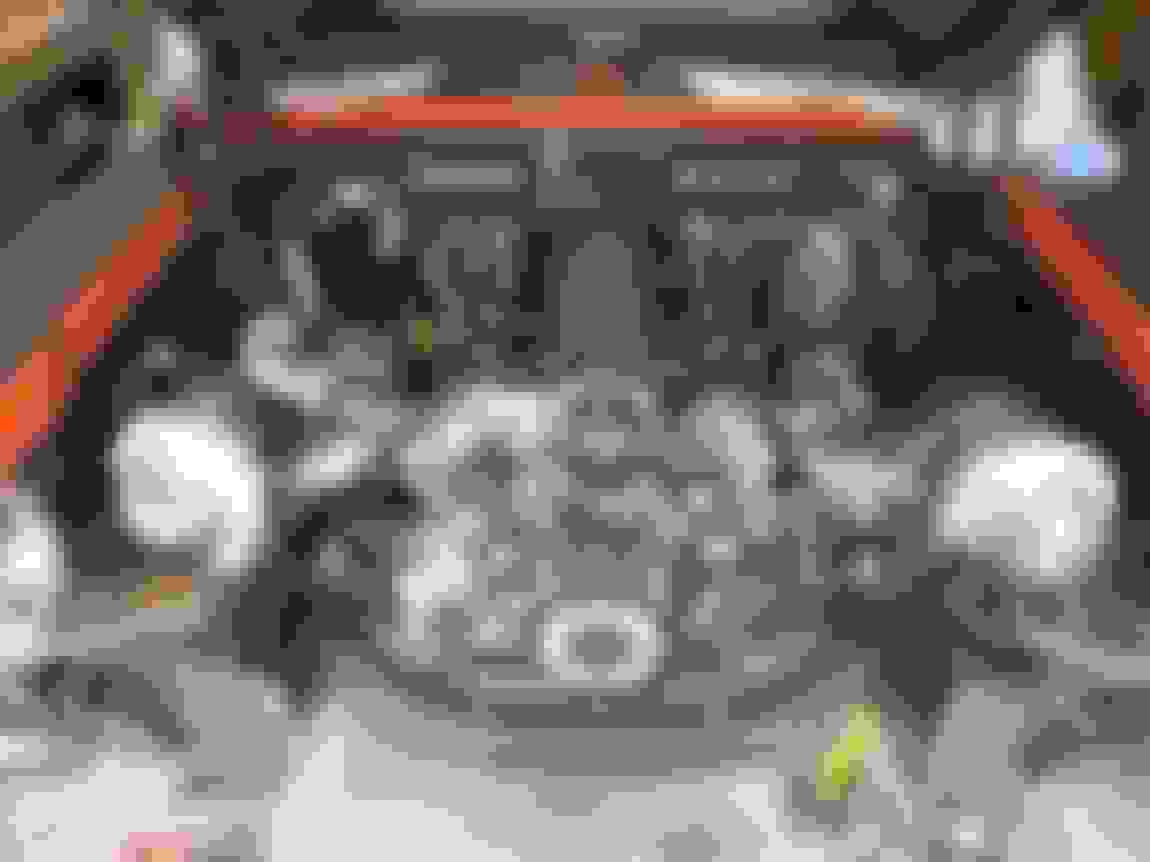
This is another update somewhat-long in the making, the turbo feed lines.
In keeping with the bent 1/4" stainless tube theme, I decided to make little "feeder" lines on the top of the turbos. This does a couple things:
a) keeps the lines as far from the turbine housing as possible
b) provides a hard point to then attach a forced-bend flex line between the turbo and the subframe (I'll explain later)
c) SYMMETRY!!!
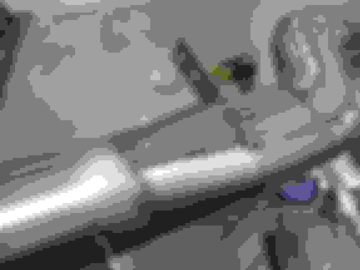
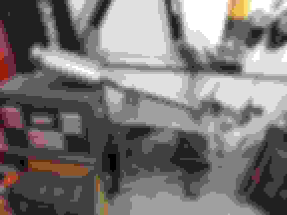
To keep these hard lines routed tightly and firmly, I bent them so I could secure them to the compressor housing with a vinyl-cover P clamp...
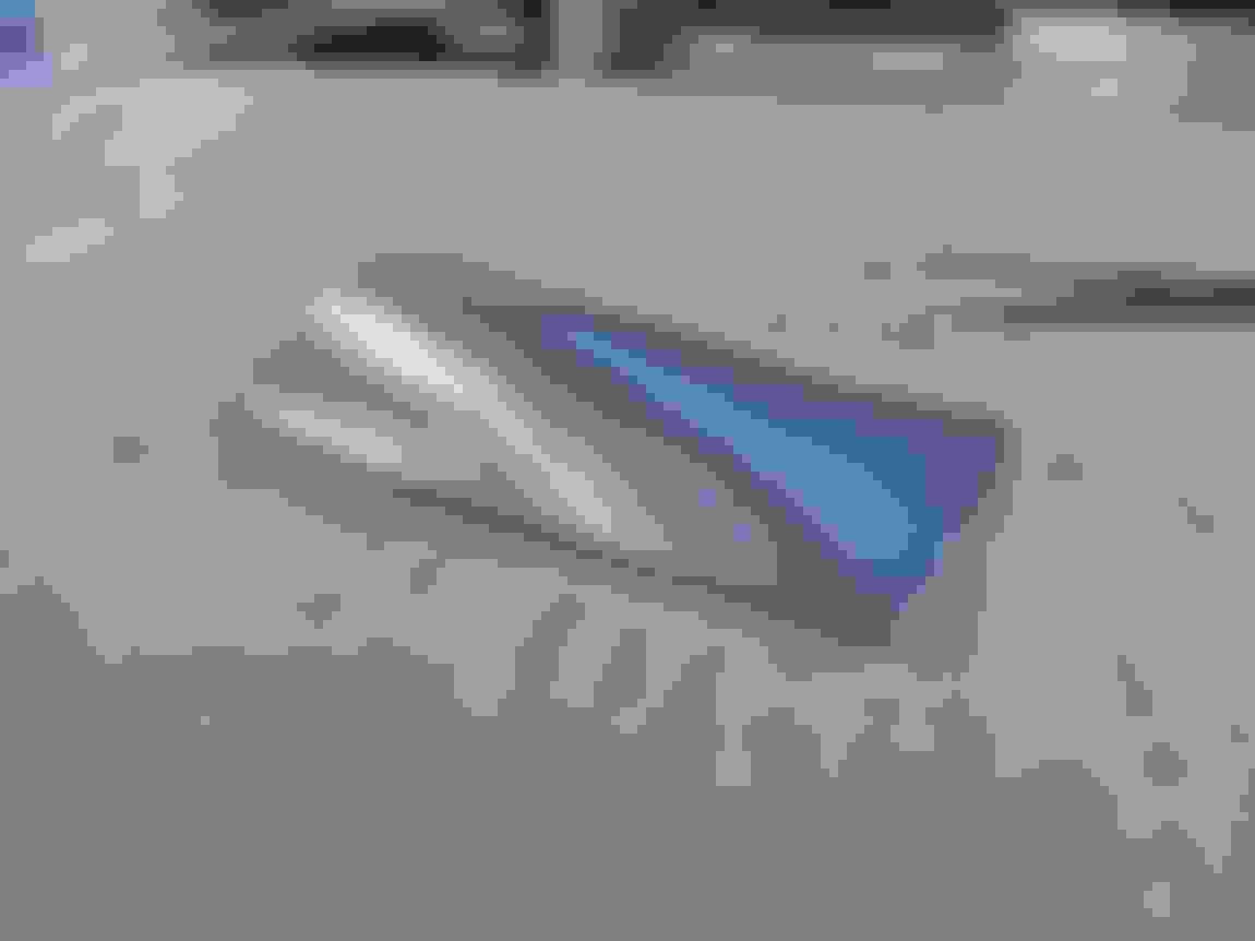
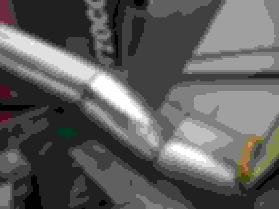
This is the forced bend flex hose as I was mentioned...
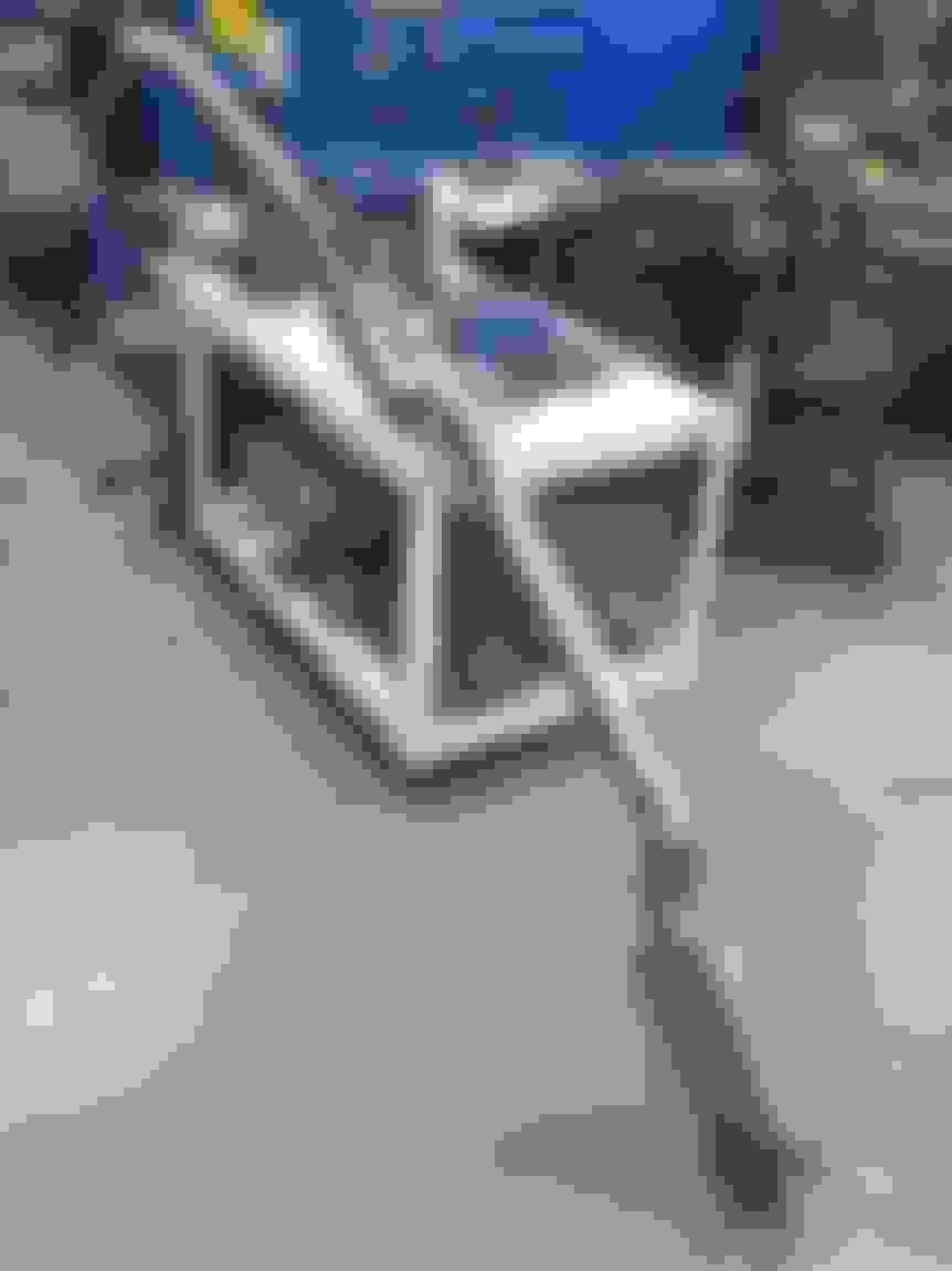
The reasoning for mounting the turbo feed line to the subframe was:
A) to get it tucked out of the way vs having lines just floating randomly in space like you usually see
B) I'm going to mount a machined aluminum "oil junction block" mounted on the subframe rail directly below the driver side turbo. This will serve several purposes:
B1) hard mounting point on the subframe to anchor the flexy -10AN oil cooler lines coming off the engine
B2) hard mounting point to allow option of soft (flex hose) or hard (aluminum 5/8" line) feeding the oil cooler in front of the intercooler
B3) threaded location to mount the oil temperature sensor on the return side from the oil cooler
B4) have two angled (30-40 degree) ports for turbo feed lines on the cooler-return side, to mimic a Y-fitting (instead of plumbing 90* tee fittings)
Very well thought out! Do you still plan on using the modified inner fenders?
Yes.. getting there! I used the inner fenders when mocking up tire articulation, to see where the fenders needed to move to, to then finalize turbo placement. But I have a feeling the actual modification and installation of the inner fenders will happen well after the car is back on the road and sorted out. Just like what happened when I built the single turbo setup.... oi! Haha.
Well done Joe! Small lines like that and electrical wiring have special places in my heart. My eyes tear up when they're done cleanly with the right fittings and routing instead of just connected and cluttered. Yours look very good. Much cooler than buffing paint and walking around at car shows.
I was going to ask you if you were a instrument fitter. Bending tubing is getting to be a lost art.. Good Job!!
Haha nope.. I'm a computer-starin' mechanical engineer. Truth be told, I hadn't once bent any actually-hard line before maybe a month or two ago when I dove hard first into all the boost lines. I had only hand bent the aluminum fuel lines on this car as well as the brake lines, but we won't look at those since they're kinda all over the place haha.
Thanks! I'm satisfying a particularly nerdy part of my engineering brain that I previously didn't even know I had the capacity for haha.
I know EXACTLY the feeling. That's why I don't feel bad about spending stupid money on tubing and wiring tools. I LOVE the process and the result. Very gratifying!
I know EXACTLY the feeling. That's why I don't feel bad about spending stupid money on tubing and wiring tools. I LOVE the process and the result. Very gratifying!
So I bought a Brother industrial/electrician's label maker... to print on heatshrink tubing.... to label the wiring for the sensors that I'm pretty sure I'll remember the association for anyways.... oi!
This week I've been chipping away at some of the final welding on the rad shroud, as well as starting to tack weld together a radiator bracket structure to test fit and hopefully tack weld onto the existing gutted core support still on the car.
Test fitting the silicone high-temp seal in the channel...
Looks to have decent compression on the seal against the radiator... only mocked up the top and bottom seals so far...
Got some "4-row HD radiator bushings" from Original Parts Group, P/N ULR004.. they're the biggest ones I could find dimensions for on Summit so thought I'd give it a shot. They're close but still not big enough for my ~3.5"-thick radiator with shroud installed...
A little trim and they'll work with the mounting design I have in my head...
1" x 1" x 1/8" L channel on the bottom to tie the two vertical 1" x 1.5" x 1/16" rectangular tube side supports...
This is a trimmed 1/4"-thick L bar that will act as a base to mount the "bushing brackets" to.. I wanted to have some form of modularity when it came to supporting the rubber saddle bushings in case I wanted to adjust the front/back location of the radiator relative to the engine in the future...
Some 1/16" plate on the outsides of where the radiator will be just to add some rigidity and reduce flex of the bottom L channel...
These trimmed L plates are the "modular" part of the bushing support design. If needed, I can remove these in the future and slot/redrill the holes or make new ones to shuttle the radiator forward or backwards for whatever reason....
The bushings currently place the radiator offset 3/8" back from the steel structure I'm making, which is the nice compressed thickness of the silicone seals, if/when I eventually seal the radiator itself to the core support structure...
With the radiator removed and the steel structure flipped over, this is what the intercooler would now look like if viewing the car from the front...
Ample gap on either side of the intercooler to the steel structure, with the idea that if the intercooler needs to be removed, it can just be lifted directly up without having to remove the radiator or grill or anything additional other than the charge piping...
This angle shows why the steel structure was clearanced/necked down at the bottom (and why the 1/16" plate gusset was added to the side to reinforce)... the necking is to clear the charge piping and couplers with the intercooler slammed rearward directly against the radiator (worst case fitment)...
Joe spends more time in the fab shop than doing his job. LOL
Hey! I put in full 8hr work days.. and then a couple more hours after haha. So many compromises to get this car done.
Rad support structure mocked up in the car.. fit as expected....
Rad support hangs down below the bumper, but once painted black it should mostly disappear considering how low the car is. Adding a chin spoiler later on should help too...
Made sure there's enough gap between the fans and the accessory drive to easily stick a hand in to install a belt, for maintenance sake...
Got the engine bay fuel lines wrapped up. I like using these vinyl-coated P clamps, adds a certain amount of industrial purposefulness vs using pricey or fabricated CNC clamps etc.
Fuel routing is from the pump to one fuel rail, then transfers over to the next rail, then into the FPR, then back to the tank.
More symmetry! The lines are extra bendy to be nice and friendly for engine vibration...
Another detail to the build I wanted to try and include was a factory exhaust manifold heat shield on the driver side. I originally thought it would add a nice OEM touch, and best case it would help a bit with heat management around the brake M/C and the steering box. I had to trim the front cylinder off for clearance to the downpipe, and was pleasantly surprised to see that there's actually some insulation material sandwiched between the stamped layers of steel...
Got around to wrapping up the dual exhaust welding this week. Spent 6hrs one evening... 1 hour making the fill-in plates for the homemade round-to-oval transitions, then 5 hours of welding... it was so hot and awkward working around these gigantic pipes, but it's all done and ready to install for good!
Smaller plate on the bottom side of the pipe...
Ghetto but effective metalworking tools...
Larger fill plate on top side of the pipe...
Fit pretty well... didn't have the mental energy in me to make them fit absolutely gapless and perfect like you see on Instagram...
So big and awkward...
Lots of standing and hunching over to get at a lot of the welds....
Here's the slightly longer pipe, the passenger side....
This next pic just goes to shows the expansion and shrinkage from welding that a lot of people don't take into account. In the picture, the left side of the pipe is the top side, and the first side I fully welded up. It WAS completely flat and flush when I tacked it together during mockup. I knew that warping and shrinkage would happen so I tried to be smart about it... there was no way I was going to keep jumping from front to back and top side to backside in an attempt to even out the heat introduced into the pipe, so instead I methodically started at the front and worked my way to the back, only welding the side facing up. I welded to the center plane of the piping then moved on. I then let the whole pipe cool down (worked on the other side's exhaust pipe). Once cool and fully contracted, I then flipped the pipe over and did the same process of starting at the front and working my way back.. hoping to introduce the same amount of heat and thus re-bend the piping back.... to being straight. And it worked! Anyways, the below pic is just showing the pipe after having one side completely welded, and the resulting warping from shrinkage....
Both pipes ended up straightening back out once cool (luckily) and now all that shitty welding work is done and behind me!
Here's another side project that I forgot to update on.. I wanted the dipstick to be shorter for aesthetic reasons, so I thought I'd do it simply and get the LS3 dipstick+tube to match the new Holley pan. Well, the curvature and placement of the dipstick tube mounting tab squarely interfered with the CTS-V manifolds in a flipped orientation. It was really hard to get a pic of it, but there was simply no way the LS3 tube's bracket was going to match up with the threaded hole on the head no matter how much bending I did to it. So I decided to then go back to the truck dipstick tube and shorten it, to lower the top of the dipstick.
Here is the truck LQ4 dipstick and its crazy height....
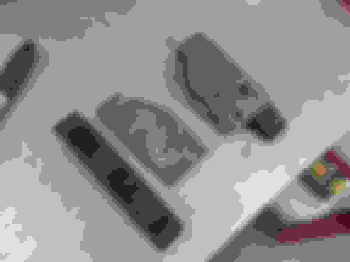
This shows how much better/closer the truck dipstick tube bracket is to fitting around the CTS-V manifolds (just like the old Cmaaro LS3 manifolds)...
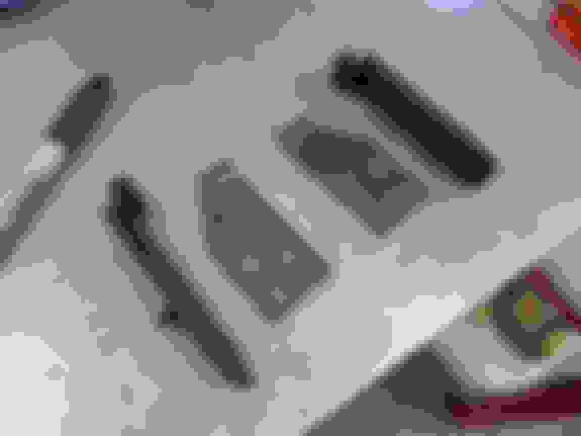
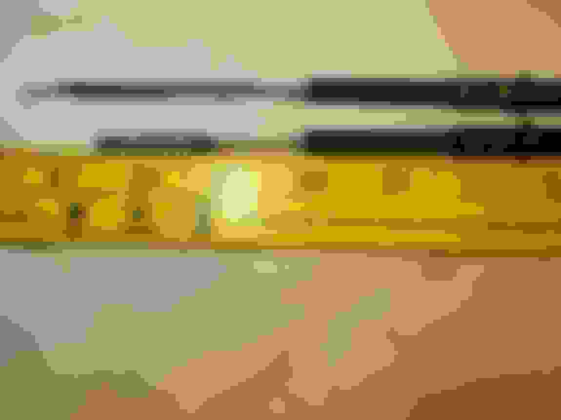
This is a comparison of the truck LQ4 dipstick+tube (top) and the Camaro LS3 dipstick+tube (bottom). Note how the mounting brackets are completely in a different location...
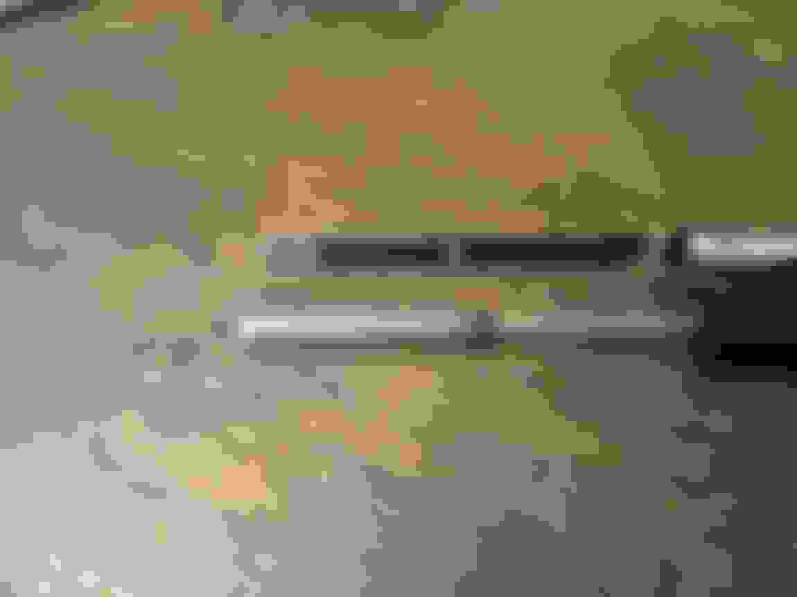
This is just a comparison of where the oil level read range is on the dipsticks.. truck (top) and LS3 (bottom)...
So after deciding to keep the truck tube, it gets hacked. Think I removed about 2.5" from the overall length of the tube...
Mocked up new height of the dipstick... time will only tell if it's too close to the turbo piping and ends up melting...
Little weld.. should do the job....
I ended up breaking the existing truck dipstick when I was trying to shorten and tack weld it back together, so I got a new truck dipstick. Slightly different in length, so I suspect it is from an LY6 or something like that which might have a revised length of dipstick tube. Anyways, I was expecting the oil level range to be significantly lower than it ended up being, as shown in the pic below...
Learning from my previous mistake of not successfully cutting/welding the dipstick, I just trimmed the extra length and drilled a second hold for the "full" line in a location that matched the LS3 dipstick...
Not a drastic height difference, but enough to tidy things up a bit and make it worth my effort I think...


 07-09-2018 | 03:05 PM