When you click on links to various merchants on this site and make a purchase, this can result in this site earning a commission. Affiliate programs and affiliations include, but are not limited to, the eBay Partner Network.
I plan to have 2 Hydramats, one on each side of the tank. To connect two mats to two pumps, I'm going to try an X-shape junction block, with two ports on one side sucking from L & R mats, and the remaining two ports on the other side of the block feeding the two pumps. My thinking behind this is that: one or both pumps can suck from one or both Hydramats, depending on fuel level and sloshing conditions.
The "crossover" part in the middle of the X is not a circle but an oval, designed to not be a choke point. The tap-drill size for 1/4" NPT thread is 7/16", so the drilled holes are offset such that the width of the center will produce a cross-section that is about 10% larger than a pair or 3/8".. so no throttling should occur.
Here is the "more or less direct" path of fuel flow...
Thanks! I figured if I fail or see issues in anything it's just best to share.. no need to only show the successes.. maybe I'll help someone else out too.
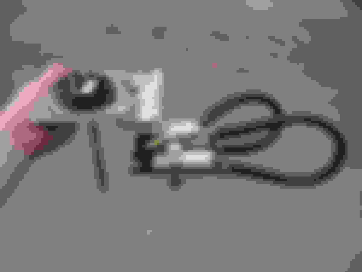
At lunch I got a new solenoid and fuse block for the fuel pumps. I'll make a panel that mounts to the batter tray in the trunk, to have the solenoid and all fuses easily accessible versus hidden under the car and inaccessible.
The solenoid is an 85A unit with a dedicated ground stud, just to be sure of getting a good ground on it, and on its output terminal I mounted a Blue Sea 4 fuse distribution block. This fuse block can handle 30A per channel or 100A total, and I will use it to have a 25A fuse for each individual pump's 10ga power wire.. so it'll be easier to diagnose any issues in the future. Also there's room to add more pumps if needed.....
Ok... monster update time. The girlfriend has been away in Maui for the last week which meant I could really get some work done this past week (at night).. and then 35 hours total work between Friday 10am and Sunday 9pm! Holy crap.
Got the gas tank all wrapped up, used the fixturing table at work to set my maximum depths and perimeter of where I need to keep the pumps and stuff within to be able to still install it into the tank.
I made a Y-block that takes two 1/8" NPT threads (for 5/16" hose barb fittings) and turns into one 3/8" NPT thread (for this wonky 90degree male-NPT-to-female-8AN...
Always important step... constantly making sure things still install into the tank!!....
What I usually like doing is making threaded backing plates for stuff that needs to bolt on.. it just makes life so much easier to not have to fiddle with holding a nut with a wrench. Below is the SpeedHut brand capacitance fuel level sender...
So here's the franken-monster fuel pump assembly. It looks aggressively large, but this was using primarily 3/8" hose for least restriction, and allowing very conservative bend radii to make sure the flow is happy...
This is the layout of the Holley Hydramat 15"x3" mats...
Attached the 3/8" hose to the Hydramats before installing them, then trimmed to length once installed just to make sure I didn't accidentally cut the hoses unworkably short if I just guessed...
Test-fitting... oi!
I was careful to squeeze the hoses in as I was working the pump assembly in, and constantly inspecting for cuts/damage. Despite what the tank cutout looks like in the pics, it's actually got a very smooth/rounded edge on the access hole.. I had no issues running my finger on it without cutting or even scratching myself...
Here is the assembly installed! In this pic I was doing some testing to make sure the pumps built pressure and flowed without interruption as I tilted the gas tank side-to-side, with about 10L of gas in it....
Next up was to start wiring the pumps. On the right are the previous pump wires at the Deutsch connector, and I'm pretty embarrassed by the crimps I did from 5+ years. On the left is a much better style 360-degree-crimp terminal that I will be using for this connector, which should allow a better electrical contact...
Here's the four-sided Deutsch crimping tool I got on eBay for I think $10. This one has crimping dies for 12ga, however I don't have any other sizes nor do I know if they're swappable (although I imagine they should be).
The cool thing is this tool has "Grumman" etched in it. Is it possible it was once used to wire jet fighters...???
12ga power wires and 14ga ground wires. I'm grounding straight to the battery, but more on that in a bit...
This new capacitance fuel level sender needs ground & 12V in addition to the level signal, so that was some extra wiring needed.
Next up, I needed to make an easily-accessible fuse block center in the trunk, next to the battery. Again I used the fixturing table to mock up the dimensions of the batter tray and battery profile, to make sure the bracket hugs the battery closely but not too closely...
This is the battery tray I made years ago, bolts thru the trunk floor.
Two of the fuses (25A) are between the 85A solenoid output and the fuel pumps, and the third fuse (5A) is between the solenoid and the fuel level sender.
While the car was jacked up, I wanted to lower the trans and pull the reverse lockout solenoid out to modify it.
I have no issues "keeping it simple" and having to override the spring in it to engage reverse, but since I've swapped in a 4th gen Camaro OEM T56 Hurst short shifter, the effort to engage the lockout spring increased to an annoyingly high amount.
***NERD ALERT*** I used our huge universal push/pull tester to see what the spring rate of the reverse lockout solenoid...
The spring was preloaded quite a bit, which explains the quick jump in spring rate at the beginning. 127N force (238-111) for 7mm travel equates to 101 lbs/in spring rate... stiff!!
To get a more accurate reading of the spring rate without the preload, I tested just the spring itself...
It took 225N force for 13.6mm travel, so 94.5 lb/in.. I'll aim to roughly half this spring rate with a new setup to start.
I went to the local auto parts store and found an assortment of springs to test. I needed it to be 7/8" outer diameter or less, to fit inside the lockout housing, but I was flexible on free length, wire diameter, and outer diameter.
After testing several, I settled on this spring as the base.. 7/8" OD with a 0.080" wire diameter...
I cut the spring down in length until it was the right length (to bump up the spring rate), then I made a 3.5mm thick spacer to preload the spring to bump up the starting force...
Fully compressed, no coil bind...
New setup is 60N force for 7mm travel, so 49 lb/in.. a good starting point to test...
While I was doing reverse lockout stuff, I decided to tweak the shifter position a bit too, to push the shift **** forward a bit but more importantly to angle it left, moving it closer to the steering wheel. So I made this little angled wedge threaded adapter...
So I slammed the car back together on Saturday, drove it out of the garage Saturday night at 10:30pm, and cruised to a car meet Sunday 10am!
Car runs real well. I pressure tested the renewed fuel system to 90psi, no leaks. I have it set at 44psi base fuel pressure when at idle, ramping 1:1 with each pound of boost (to an estimated total fuel pressure of 65psi as viewed by the pumps).
Meanwhile on Sunday morning Marktainium also dropped his gas tank replaced a bad Walbro 255, and got the car roadworthy for the first time in a year, and I met up with him at 11am! Fun day with the boys, making whistle noises.
My drive to the car meet was my first real boost tuning session, so I had a couple times when I rolled into boost a bit too quickly and I guess the Holley couldn't learn-correct my AFR's quick enough, and reassuringly my AFR warning cut spark, and car fell flat on its face. The rest of the way I slowly rolled higher into the rpm's and deeper into the boost, building a decent fuel map learn table. I'm running the lowest springs my wastegates came with.. I believe 6psi, and I eventually made my way up to 180kPa or 11.5psi boost.. holy crap, this thing already hauls so much *** with such deep torque yet such precise throttle response.
It's fun on the highway in 5th or 6th gear pulling good vacuum just humming along at 15% pedal and 16-1700 rpm, then I move my right foot little bits and I can exactly see my boost gauge spike correspondingly to specific vacuum numbers or even barely into boost, and hear a range of whistle tones... it's like owning a foot-operated musical wind instrument!
Tell me again why you don't have the reverse lockout solenoid activated by the Dominator.
Andrew
At this point, I'm not sure.. another pinout and extra wiring/relay?
The original reason, which I guess is the continued reason, is I haven't been able to read VSS in.. forever. Originally I had the VSS wiring connected to the wrong input pins on the Dominator, then I connected it to supposedly the right pins but didn't have it configured as the correct input type, then I "corrected" the input type and I still can't read VSS on the Dominator gauge screen or export it to my analog Speedhut gauge. This has been the same for two different T56 transmissions, so maybe it's the VSS itself that's the issue.
Having a working speed input really opens up several advanced table possibilities that greatly increase drivability, especially with a manual transmission. You can post details here or shoot me a PM. I am curious as to how exactly the VSS is wired and how it is configured. Also, to make the laptop gauge display function, you must double click on the gauge and tell it what channel to display. If you want, send me your latest global file and I will help you sort this out.
Thanks Andrew, really appreciate the offer. Trust me.. I wish the VSS worked. I'll have a look thru this morning's commute-into-work log and corresponding tune (isn't that nice to say!!?!) and send you a PM about it.
Thanks Andrew, really appreciate the offer. Trust me.. I wish the VSS worked. I'll have a look thru this morning's commute-into-work log and corresponding tune (isn't that nice to say!!?!) and send you a PM about it.
I don't need the log, just the global file. What version of software are you using?
I don't need the log, just the global file. What version of software are you using?
Fair enough, I was just going to look at the log at the same time for my own personal interest. I'm on Version 5, Build 31. Want to PM me your email address and I'll send it over?


 04-15-2019, 01:09 PM