


LQ4 into a 3rd Gen/1972 Nova
Thread Starter
Joined: May 2007
Posts: 1,806
Likes: 46
From: Vancouver BC, Canada
Well it's rainy as hell up here, which means for the first Friday in a while, I stay in and keep it low-key... wiring.
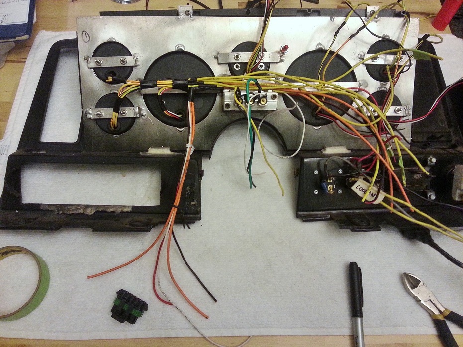
Since I'm at it doing a whole new wiring setup, the old cobbled-together wiring from 2.5 years ago (knowingly didn't care as much as I should've because I just wanted to drive it already) just cannot be tolerated anymore. Starting with dash, which will then work back to body-side wiring (essentially bat +12V, switchable 12V, and lights/signal indicators), and also branches back to gauges in/out from ECU and gauge sub-harness bundle.
So far I'm happy with the little clean-up progress I made, as well as the overall plan I have for it in my head.
Also de-loomed the harness and started moving the sensor plugs to more appropriate loom-exit locations for nicer engine fit-up. Also moving the switchable/battery wires, ECU I/O, and fuseblocks further up the harness closer to the ECU, as they came exiting the loom practically in the engine bay.

What a mess, this has gotta be dealt with..
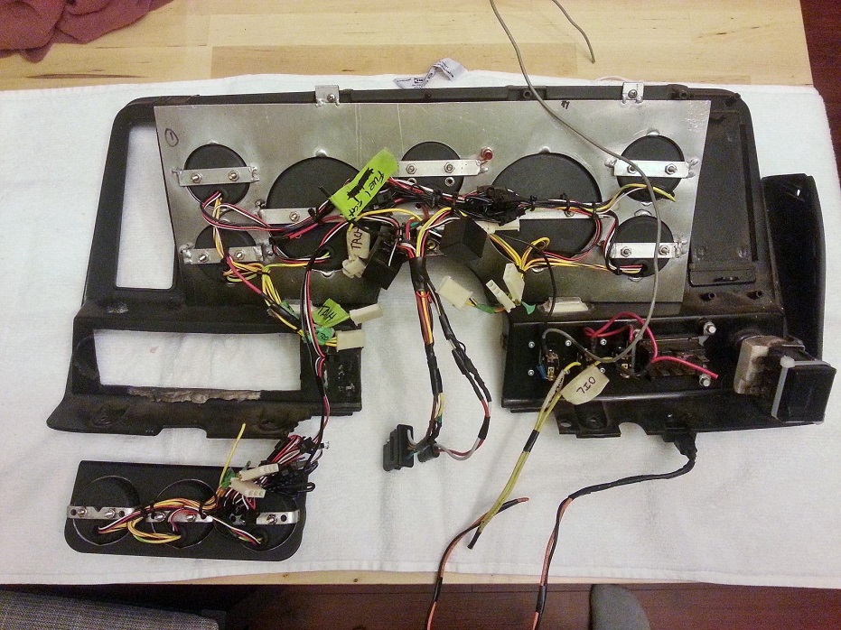

Ahhhh *sigh of relief*. This lower 3-pack of gauges has to be removable because the top lip of it covers two of the stock-plastic-dash install screws (3-pack bracket then screws into the plastic dash underside). A pleasant sign of things to come..

Since I'm at it doing a whole new wiring setup, the old cobbled-together wiring from 2.5 years ago (knowingly didn't care as much as I should've because I just wanted to drive it already) just cannot be tolerated anymore. Starting with dash, which will then work back to body-side wiring (essentially bat +12V, switchable 12V, and lights/signal indicators), and also branches back to gauges in/out from ECU and gauge sub-harness bundle.
So far I'm happy with the little clean-up progress I made, as well as the overall plan I have for it in my head.
Also de-loomed the harness and started moving the sensor plugs to more appropriate loom-exit locations for nicer engine fit-up. Also moving the switchable/battery wires, ECU I/O, and fuseblocks further up the harness closer to the ECU, as they came exiting the loom practically in the engine bay.
What a mess, this has gotta be dealt with..
Ahhhh *sigh of relief*. This lower 3-pack of gauges has to be removable because the top lip of it covers two of the stock-plastic-dash install screws (3-pack bracket then screws into the plastic dash underside). A pleasant sign of things to come..
Thread Starter
Joined: May 2007
Posts: 1,806
Likes: 46
From: Vancouver BC, Canada
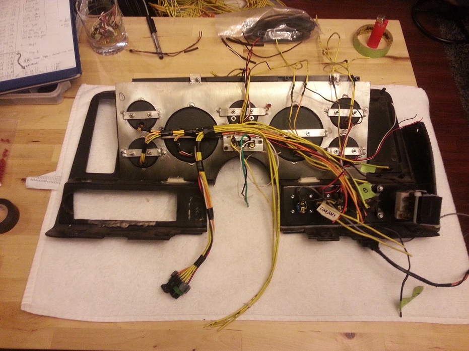
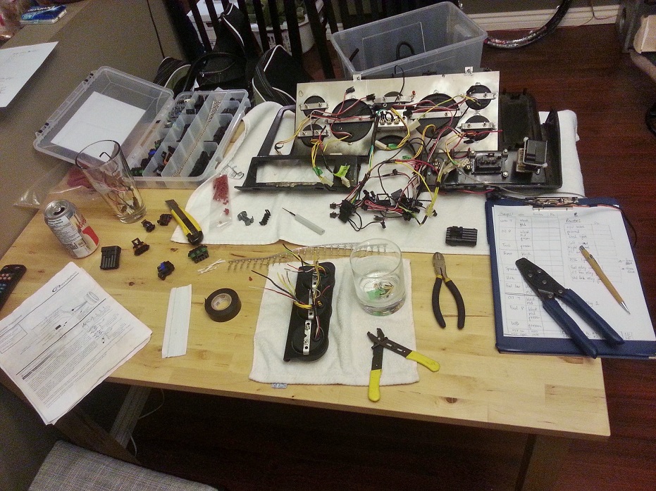
Ohh yea, there we go. FYI.. beer does NOT help with this process. I would've liked to have one main plug, but I decided to separate it up to lights/power/ECU ouputs/gauge sensor outputs.
ryan here are some detailed photos of how I did my solder joints:
Link1: https://ls1tech.com/forums/17585541-post866.html
Link2: https://ls1tech.com/forums/17612663-post877.html
Link1: https://ls1tech.com/forums/17585541-post866.html
Link2: https://ls1tech.com/forums/17612663-post877.html
Thread Starter
Joined: May 2007
Posts: 1,806
Likes: 46
From: Vancouver BC, Canada
That's how I did my soldering too, except the stripped length of wire was slightly shorter (about 3/8"), and obviously only 2 wires joined. I have more to do tonight, so can take pics if for some reason Clint's pics don't do it for you. Man, stripping all weekend gets tiring, talk about late nights... haha.
LS1 Tech Stories
The Best V8 Stories One Small Block at Time

Topdon ONE vs. Artidiag 800 BT2: Which is the Diagnostic Tablet For You?
Pouria Savadkouei
Gas Monkey Built a 6-Wheel Ferrari Testarossa With a Corvette LT4 Engine
Verdad Gallardo
7 Most Reliable High-Performance Engines GM Has Ever Built
Verdad Gallardo
Amazing '71 Camaro Restomod Is Modern Muscle Car Under the Skin
Verdad Gallardo
6 Common C5 Corvette Failures and What's Involved In Repairing Them
Pouria Savadkouei
Retro Modern Bandit Pontiac Trans AM Comes With Burt Reynolds' Autograph
Verdad Gallardo
Top 10 Greatest Cadillac V Series Performance Models Ever, Ranked
Pouria Savadkouei
Top 10 Most Powerful Chevy Trucks Ever Made!

Hennessey's New Supercharged Silverado ZR2 Has 700 HP
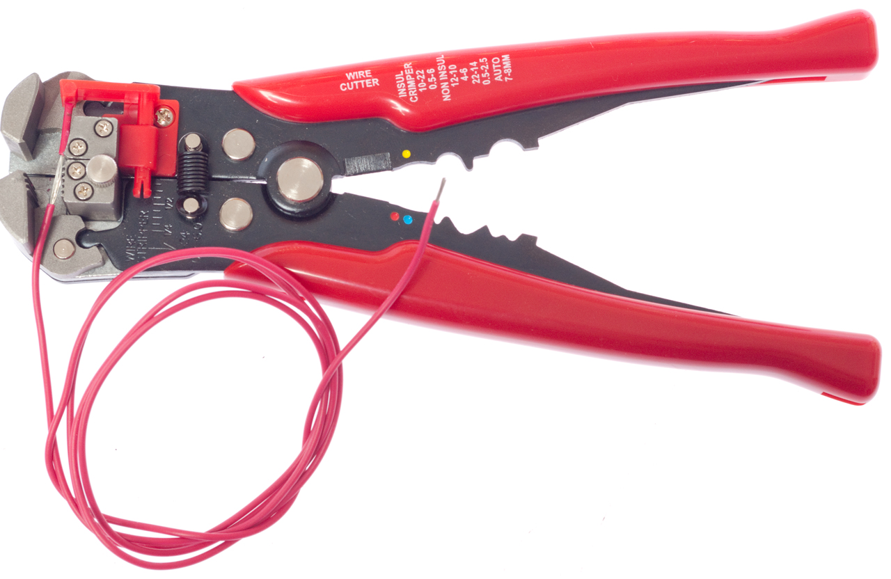
Verdad Gallardo I got some dollar bills for you if you want to strip at my place. Do you have this type of stripper? Works a lot faster and gives you a consistent strip length:
I went long on mine to maximize electrical contact and mechanical (pull apart) strength. I am really paranoid about having bad solder joints because the results are usually very hard to diagnose. 3/8" is probably fine for a two-wire junction though. Those big 5 wire coil harness junctions scare the **** out of me.
I went long on mine to maximize electrical contact and mechanical (pull apart) strength. I am really paranoid about having bad solder joints because the results are usually very hard to diagnose. 3/8" is probably fine for a two-wire junction though. Those big 5 wire coil harness junctions scare the **** out of me.
Last edited by -TheBandit-; Mar 10, 2014 at 02:03 PM.
Thread Starter
Joined: May 2007
Posts: 1,806
Likes: 46
From: Vancouver BC, Canada
Actually thinking about it, I probably made the stripped length about 1/2" or bit longer.. but for 16ga wire that's plenty of twist engagement I think.
Also, that stripper tool is awesome. I just have the diamond-shaped ghetto snipping tool. It works fine, I like that it can strip anything from 20ga to up to 4ga (2 cuts, 90* in relation to each other).. as for consistancy, that's all from the user's experience with it via "feel" haha.
Hoping to button up the dash-to-ECU wiring on the Holley harness tonight, then do gauge sensors sub-harness as well as body-side power/ground/lights plug in the next couple days. Would really like to plug everything in and try to turn it over this coming weekend....
Thread Starter
Joined: May 2007
Posts: 1,806
Likes: 46
From: Vancouver BC, Canada
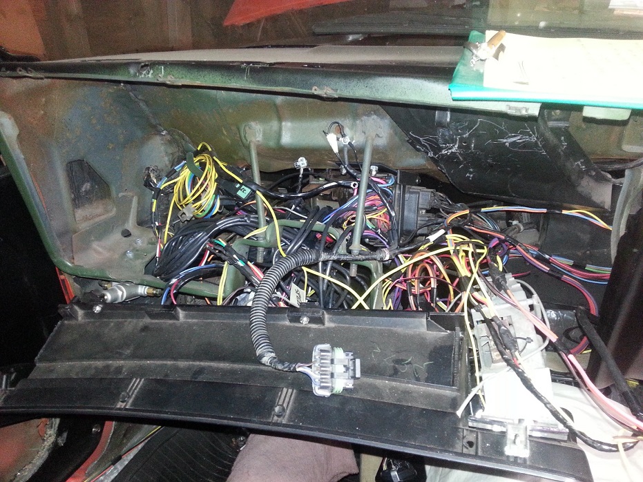
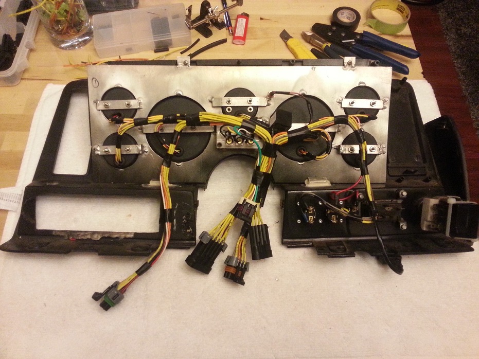
Holley wiring harness is re-organized including connections to body & gauges, and the sensor sub-harness and body power/lights are all re-wired/plugged. Just waiting on my passport to go pick up a Holley boost sensor and several other "goodies" from across the border. Hoping to do that early next week. Once I connect the Holley wastegate dome pressure sensor, all wiring is ready to be dropped into car..

Last edited by frojoe; Apr 2, 2014 at 10:28 PM.


Thread Starter
Joined: May 2007
Posts: 1,806
Likes: 46
From: Vancouver BC, Canada
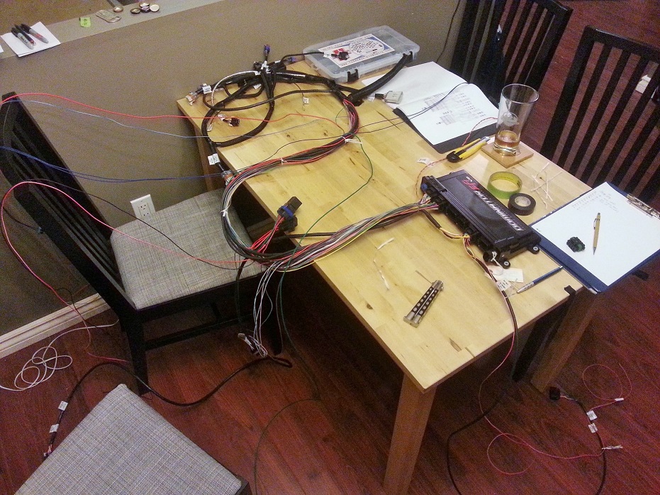
Thanks. I'd say I probably have about 15 hours into all the wiring. The majority of work was splicing/soldering/heatshrinking along with figuring out all the proper lengths for multiple wires going to the same plug.. and testing. The actual plug pin crimping was super easy and quick after learning on a couple test wires. It wasn't necessary to spend as much time on the Holley-harness side as I did, but I wanted to make sure each plug had the proper amount of length going to it from where I marked my "firewall-pass-thru location" to be, without there being excess length needing bundling that cluttered behind/under the manifold, firewall, etc.
The Holley electronic boost control system uses a MAP sensor (pre-tuned sensor values are programmed in for either a Holley branded one or a GM-part-number-specific one, or user-defined) so I'm re-using my GM 2.5bar MAP, but it also needs a compressor pressure value from before the TB, and I'm unsure of my Speedhut boost gauge sensor enough that I don't want to fiddle with user-defined values/offsets in the Holley program, especially for finely-controlled boost. The Holley sensor will connect to the pressure-reference-signal side of the wastegate (wrote BOV before for some stupid reason, obviously that was wrong) aka the "dome".. which is just the top.
The Holley electronic boost control system uses a MAP sensor (pre-tuned sensor values are programmed in for either a Holley branded one or a GM-part-number-specific one, or user-defined) so I'm re-using my GM 2.5bar MAP, but it also needs a compressor pressure value from before the TB, and I'm unsure of my Speedhut boost gauge sensor enough that I don't want to fiddle with user-defined values/offsets in the Holley program, especially for finely-controlled boost. The Holley sensor will connect to the pressure-reference-signal side of the wastegate (wrote BOV before for some stupid reason, obviously that was wrong) aka the "dome".. which is just the top.
Last edited by frojoe; Apr 2, 2014 at 10:28 PM.

Thread Starter
Joined: May 2007
Posts: 1,806
Likes: 46
From: Vancouver BC, Canada
It's awesome how flexible the Holley system is. Any free ECU-side pin (AKA isn't dedicated to main harness function) is tunable. You just highlight the pin # on the computer program and select from the following:
Inputs:
- 'hi' +12V trigger signal (4.5V-24V range)
- 'lo' ground trigger input
- 0-20V sensor input
- 0-5V sensor input
- specific thermocouple input (select pre-tuned values from dropdown menu)
- frequency input (select pre-tuned values for usage, including VSS)
Outputs:
- 'high' power switchable +12V
- 'lo' power switchable ground
- PWM +12V
- PWM ground
Once you physically connect a pin, you look at the pinout map in the program, and you drag and drop "pre programmed" signal input/output functions (dome pressure sensor signal, VSS, etc) onto the pin # on, and it's programmed!

Thread Starter
Joined: May 2007
Posts: 1,806
Likes: 46
From: Vancouver BC, Canada
No Mission raceway that early for me. But hoping to have a productive 2 days this weekend.. work has been ridiculous so I need to blow of some steam with gigantic, glorious, violent burnouts and boosty pulls.


