When you click on links to various merchants on this site and make a purchase, this can result in this site earning a commission. Affiliate programs and affiliations include, but are not limited to, the eBay Partner Network.
Thanks guys, I'm very content with the progress so far.
Andrew, no.. the turbo's currently are just supported by the piping. I'm sure to some this may seem less than ideal, as it did to me when I first started thinking about trying a twins setup, but that was the main reason I opted for the CTS-V manifolds, to move the flange further forward in order to reduce the length of the hotside piping and thus the cantilever.
This is also the reason I retained the 2-bolt OEM flanges instead of cutting them off and welding on more aesthetically-pleasing v-bands.. for some extra strength at the joint from the turbo weight. I'll also be welding the manifold flanges on the outside and inside, potentially with some extra gusset plates in the locations under highest tension.
The piping is also schedule 40, which is something like 0.24" thick, so with a deep chamfer at each weld joint and multiple weld passes I'm confident that almost that entire thickness will end up being made up with weld bead, making the piping itself quite strong.
For turbo weight, it's actually not that bad. The entire assembly as shown on the benchtop is reasonably liftable by one hand. There's also the fact that practically everyone else has made twins setups (with apparent success) having them supported only by thick wall piping or thin wall headers and tubing.
That all seems reasonable. I just get nervous with a big hunk of weight hanging way out there, especially when you consider the dynamic nature of an engine, moving around and vibrating. The vibration is particularly of a concern. Again, you're probably OK. I probably worry too much...LOL
That all seems reasonable. I just get nervous with a big hunk of weight hanging way out there, especially when you consider the dynamic nature of an engine, moving around and vibrating. The vibration is particularly of a concern. Again, you're probably OK. I probably worry too much...LOL
Andrew
I see where you are going, and I was concerned too. I guess here it will be a case of making all the hot side plumbing rigid enough via heavy wall tubing/pipe, gusseting, and any other reinforcement necessary.
I see where you are going, and I was concerned too. I guess here it will be a case of making all the hot side plumbing rigid enough via heavy wall tubing/pipe, gusseting, and any other reinforcement necessary.
and it makes me think you have nothing to worry about!
Sorry, didn't mean to hijack the thread, but that video seems appropriate to the discussion. If there is an engineer in the house, we can maybe get a better perspective.
Andrew.. cool vid! Very cool about how the traffic poles are made. I was actually sitting at a traffic light the other week and thought about the sizing of the pole (there were 3 lanes' worth of traffic lights cantilevered) and I wondered how much the poles and arms flexed due to settling under the weight, and how much weight they carry.
I am actually a mechanical engineer, although I normally work with 7005 and 6061 aluminum and carbon fiber.. so high temperature austenitic steel automotive use is not really my expertise. But after a lot (more than I care to admit) of thought and design iteration in my head, I'm pretty at peace with how the turbos are cantilevered in front of the engine. I feel I've done everything in my power to limit the amount of stress on the welds (packaging-wise) so that the longevity of the piping now depends on my welding ability. But making it thick-wall and giving it lots of filler should help compensate the fact that technically SS304 really isn't the ideal material for high temperature welded stainless as it can experience creep at the welds after stress cycling the heat affect zones under high temps.
Yesterday I tried a different routing of the wastegate downpipe, routing it above the turbo downpipe to get that heat away from the radiator+fans and the turbo oil drain. I originally lightly mocked it up this way but thought it didn't look so good, but Mark brought me back to my senses.
I've ordered some 2" stainless bends that have a tighter 2.0" centerline-radius bend... the 2" piping in the pics below is 3.0" CLR. Tighter bends might make the wastegate piping appear less visually prominent. I also like that the wastegate feed pipe is now a bit more acute to the turbo hotpiping. I can still get at the crotch of the weld with some TIG torch tungsten stickout, so it looks tighter than it actually is.
Also awaiting more 2.5" schedule 40 elbows and turbo discharge v-band flanges, as well as Precision T3 flanges that match the turbine housing inlet.. so at the moment I can't really make any more mockup progress on the wastegate piping and downpipe, or any of the passenger side for that matter.
I tweaked the turbo hotside a bit.. rotated the piping on the flange slightly to bring the turbo inboard and further away from the tire for more inner fender clearance. This ended up swinging the compressor housing and intake elbow closer to the radiator support, so cut 3/8" out of the straight tube part of the turbo hotside.
Before...
After...
Naturally, this now cramped any room I had left for asymmetric charge piping between the intercooler and the throttlebody, so I'll have to do a bendy tapered merge pipe from 3.5" at throttlebody to 2.5" by 4.5" overall width oval on the top of the intercooler.
Removing that 3/8" really straightened the turbo out. Much more visually pleasing. Are you going to have any problem closing the hood with the turbo housing so high? Does the hood have any inner structure?
Yeah I was never really opposed to having the turbos angled somewhat (tucks turbine housing inboard but puts compressor housing outboard, angles downpipe more towards engine) but it does look better closer to straight.
I've left the hood on this whole time specifically to check clearance at each step of the process.. the compressor housing has 1/4" clearance to the underhood bracing, which is about 3/4" proud of the underside of the hood skin, so I may trim that area of the brace if I end up seeing evidence of contact with engine movement/vibration.. that'd be an easy to fix.
You're doing some great work. After watching that light pole video, I am no longer concerned (not that it really mattered) about the turbo weight. I like your attention to detail and I am mostly jealous that you're playing with turbos, and I am not. Carry on!
Did you make or buy those hood pin/spring brackets? Those a slick. how do you like them? Any issues with the hood bouncing around or do the springs keep it up against the pins?
I made the hood pin brackets.. no issues thus far. The springs are somewhat firm but only require 1/8" compression to insert the hood pins, so they're preloading the pin but not by a ton. They have 3 bolts that spread the load onto the rad support well, and the 3/4" high plate around the perimeter makes them super stiff.. so I never really had any concerns with the spring and the pin not being over top of each other. The way I did it way back was to place the pins on the hood in a place that looked visually balanced, then drilled down and made the brackets to fit. A lot of guys just mount the pins to the rad support which angles them forward in a way that doesn't fit the hood well, and puts them really close to the leading edge of the hood which I visually never liked.
While searching my old pics for the hood pin brackets pics, I also found these old ones from when I first got the car when I was 17...
Hah yeah it became immediately apparent when I first went to mock up the intercooler for the single turbo setup that the stock latch had to go.
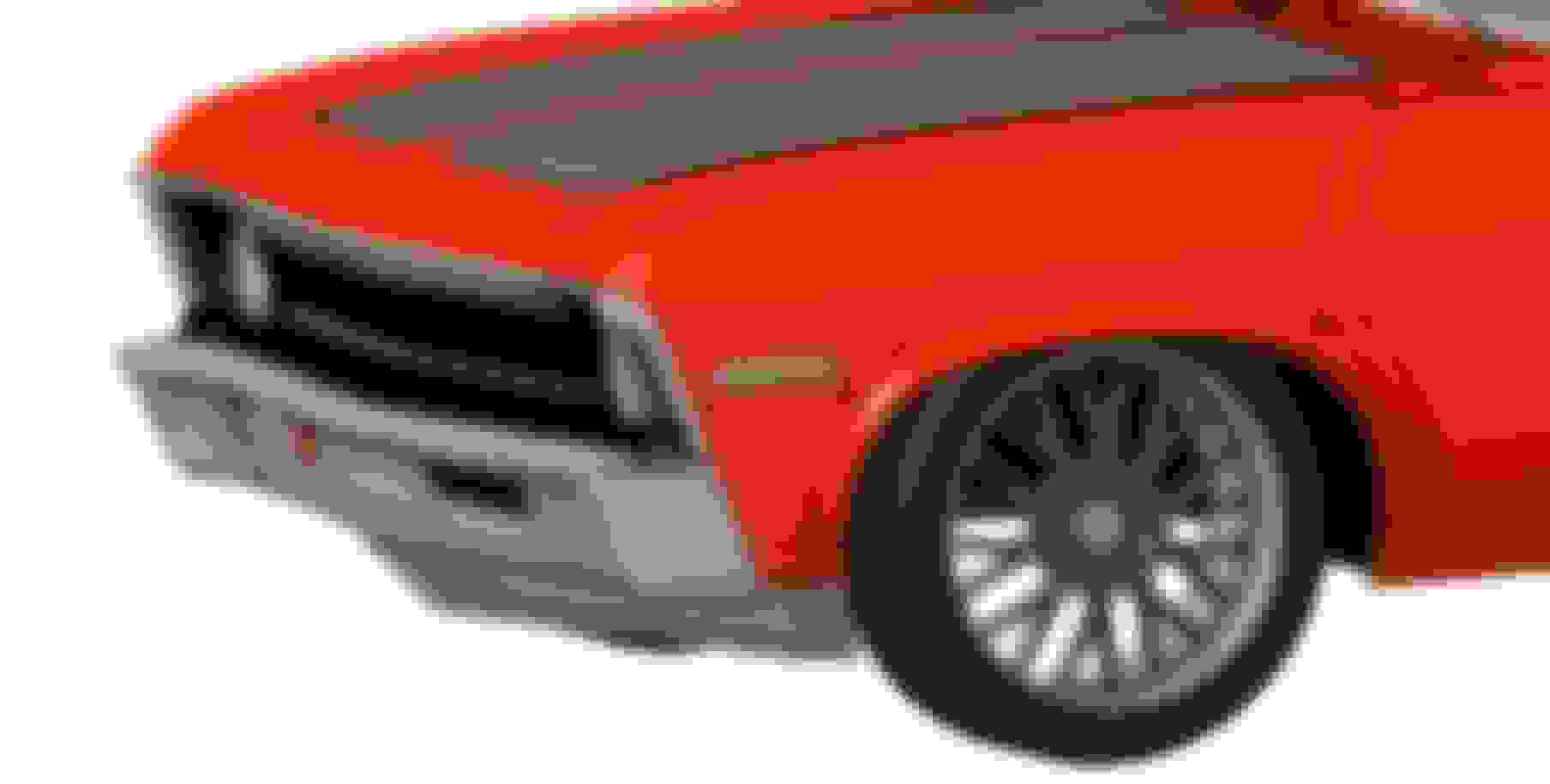
Car sure has come a long way! It was originally a grandma green bench seat I6 car with column shift 3spd auto manual steer and manual drum brakes, but when I got it it had received a crappy orange respray with clearcoat runs, ripped 70's vinyl bucket seats, and a 307 with still manual everything.
As I wait for some stainless piping and other bits to arrive, I thought I'd finally get around to starting to model an air dam aka mini-splitter idea I've had in my head for a while. I think the proportions are okay-ish enough to not look like a train cattle guard, but also not so minimal that it's pointless looking.
The "vertical" part (air dam) is about the same rake as the bumper, but much more peaked in the middle to help aid airflow getting around the car and not underneath it. On the ends of the air dam are two 1/2"-tall lips that help tumble the air so that there are vortices as the air leaves the air dam, goes around to the side and tumbles past the spinning front wheels (very turbulent air around the wheelwells). And it has a horizontal piece (splitter) that's 3-4" deep across the width, to aid a bit in downforce but also prevent the diverted air from just getting funneled underneath the car.
This design or a piece similar to it would help build up a high pressure zone in front of the car (in front of radiator) as well as reduce the pressure build up in the engine bay by reducing the air that flows under the car. Inner fenders will also go a long way in helping keep airflow (and thus air pressure) from entering the engine bay from the wheel wells. It also helps airflow thru the radiator by closing out underneath the bumper, so air entering the bumper cutouts has nowhere to go except thru the radiator.
I have no idea if this is remotely close to what I'll end up making, but it's the design I've had in my head and wanted to hash out in 3D to see. I'll cardboard it up at some point after the turbo stuff to see what it looks like in real life. I also need to keep ~4" ground clearance since I need it to still go over speedbumps!
I wanted something that is a bit more substantial/sophisticated than just bolting on a 1969 Camaro air dam, but not as extreme as what some are doing out there as shown on these examples..
Your design is starting to grow on me the more I look at it. Will be a good project for after the turbos.
The proportions in your solid model are a lot better than some I've seen but it still seems off like the car is stretched out long and the tires don't fill the wheel wells as much as in reality. We need someone to get as a full accurate scan of a real car.
EDIT- I just looked at the video cycling the suspension and holy crap you are right on the edge of clearance. Nice job trimming! I am running inner fenders and thinking how the hell am I going to get sufficient clearance on the outside when I got to larger wheels and wider tires. I'd kinda like to run 255/40R18 on 0 offset front and rear. I'm narrowing the back to make that 0 offset possible, but I would be very borderline up front if it would clear at all. Going to drum hubs / vette brakes will help, but it's very questionable. Stupid inner fenders - I may have to trim out the center/outside section like you did and leave the rest.
Last edited by -TheBandit-; Jan 5, 2018 at 06:11 PM.
Gas Monkey Built a 6-Wheel Ferrari Testarossa With a Corvette LT4 Engine
Slideshow: The controversial Ferrari F6 swaps its original flat-12 for a Corvette Z06-derived LT4 V8 and sends power to four rear wheels through a custom-built drivetrain.
7 Most Reliable High-Performance Engines GM Has Ever Built
Slideshow:These GM engines didn't just make huge power, they survived abuse, boost, track days, and six-digit mileage with a reputation for refusing to quit.
6 Common C5 Corvette Failures and What's Involved In Repairing Them
Slideshow: From wobbling harmonic balancers to failed EBCMs, these are the issues that define long-term C5 ownership and what repairs typically involve.
Retro Modern Bandit Pontiac Trans AM Comes With Burt Reynolds' Autograph
Slideshow: A modern Camaro transformed into a retro icon, this limited-run "Bandit" build blends nostalgia with brute force in a way few revivals manage.
Top 10 Greatest Cadillac V Series Performance Models Ever, Ranked
Slideshow: Cadillac didn't just crash the high-performance luxury vehicle party, it showed up loud, supercharged, and occasionally a little unhinged...
Coachbuilt N2A Anteros Is an LS2-Powered C6 Corvette In Italian Clothes
Slideshow: A one-off sports car that looks like a vintage Italian exotic-but hides a C6 Corvette underneath-just sold for the price of a new mid-engine Corvette.