When you click on links to various merchants on this site and make a purchase, this can result in this site earning a commission. Affiliate programs and affiliations include, but are not limited to, the eBay Partner Network.
This weekend I'll be taking some detailed Nova body reference measurements to see how close the car is. Purely size-wise I'm not sure how close the model is to real life, but as far as surface detail and overall curvature & muscle lines, I gotta say I think the model is pretty damn accurate.
Some more 3D model fiddling.. luckily I'm picking up a ton of stuff tomorrow so I can pry myself away from whacky ideas on the computer and actually get some real stuff done!
Idea for hood vents, I would make them and likely just cut holes in the hood and paint match the vents and insert them into the hood, at least to start.. instead of trying to do a bunch of metal blending. I could always graft the vents into the hood at a later date when bodywork happens, or more realistically just transfer them over to a lighter hood (fiberglass.. aluminum... carbon.... who knows what the future holds). Think I'd weld studs on the underside of the vent flange to fasten them to the hood, instead of just sticky tape or epoxy'ing them on.
I'm liking the width/length overall size of the vents as well as the number of louvers.. I feel it looks kinda balanced visually on the hood, not too ricey or "gilly". Vents are located so that they more or less line up right over all of the pre-turbo hot piping. Sizing of the vents side-to-side is roughly from the valvecover over to the inner fender, and front-to-back from the turbo center section back to the center of the exhaust manifold.
Another idea is for the tailpipes. I'm a big fan of the quarterpanel 45* dumps half hidden/tucked up under the quarter panel, which is what I currently have. Mark's Camaro executed this well.. only a bit of the tip is showing to hint at what's underneath.
That being side, almost since I got the car I've been curious what integrated/frenched exhaust tips could look like. I think since I'm doing a full 3.5" dual exhaust, the tips could actually be big enough to visually look balanced on the rear.
The Nova has a HUGE rear bumper, so small tips (2.5", even 3") look a bit out of place and small, especially if they're hanging 100% under the bumper. Also don't like when the tips come straight back from beside the framerails.. spacing looks too wide and unbalanced in my eyes. Case-in-point is how I originally did my exhaust when I first got the car, 2.5" slash cut chrome tips hanging below the bumper and outboard of the framerails, they look like an obvious add-on and not really integrated at all.
Part of my order today was the new rad & fans. I've gotten far enough along with the cardboard cooling stack mockup to know that there will be good room to make it work, so was time to move to the next step of getting parts.
Radiator is a 31"x19" overall size.. actually measures 31.0" wide by 18.625" high, and the core is 28.0" wide.
Reason for getting this particular radiator are:
1) has the widest core (28.0" wide) out of any of the popular brands' 31" rads, most common core size being 25.5-26.0" wide
2) C&R is a known and trusted brand. For my build I felt the price was only slightly higher than more questionable brands (Summit, Griffin, Entropy, etc) but I also couldn't spring for a big brand like BeCool, Ron Davis, etc. Welds are very consistent and tight, serial number and date of manufacture are hand engraved into the end tank. Multiple QC stickers.. everything points to a well-produced product
3) inlet & outlet are both on the same side.. I wanted to try a dual pass radiator just to see how it goes. Quite a few on the Corvette forums swear by dual pass for cooling when limited airflow is available.
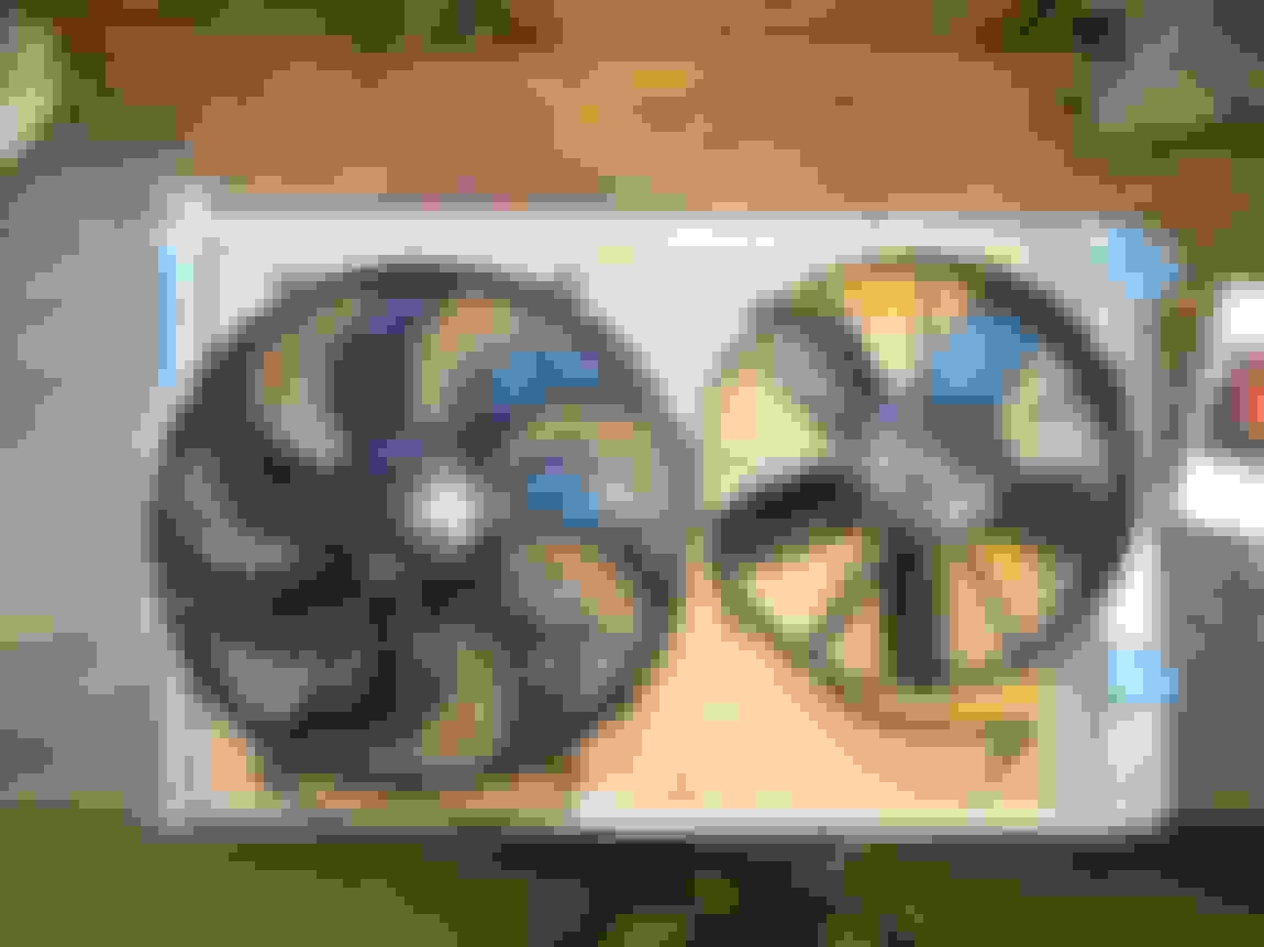
The fan setup I'm trying out is about the beefiest setup I could conjur up... the highest-amperage Derale 16" fan paired with the highest-amperage 12" fan I could find.
The 16" fan is rated at 1918cfm but at 25.4amps, which is the highest amp draw I could find out of any fan of any size, according to Summit but also searching manufacturers' websites and forum posts.
The second fan in the pic is one of my old ones (as a placeholder) which is 13" and 1640cfm @ 21.4amps. However the second fan I actually ordered and plan to try out (hasn't arrived yet) is a Derale 12" rated at a higher 2000cfm @ 24.8amps.
So total possible airflow (if the ratings are to be remotely trusted) is ~3900cfm, but at a whopping 50A. Luckily I already had the wiring setup to handle 70A continuous with a Ron Francis rad fan relay+fuse combo module.
I suspected that Derale fans are just re-branded Spal fans but about 25% cheaper, based off internet picture comparison, but it turns out that the fans are literally Spal fans just in a renamed box.
Rad is mocked up with spacers to the rad support to approx simulate a 4.5" thick intercooler, still not sure if I'm going to go that big. I'd really like to use a new-gen Garrett 3.8" thick intercooler core if I can find any core size that will work for my sizing.
I was anticipating some misalignment in the outlet/inlet, but it actually lined up better than I expected. Because everything on this damn car is custom, I'll give it a little effort to find a rad hose that might fit, but I'm expecting having to just cut off most of the rad inlet tube and weld on a bend to realign it perfectly with the waterpump outlet, and just use a straight rubber rad hose or maybe a black silicone coupler.
And fans appear to fit the accessory drive with a good 2-3" of clearance.
Like for the radiator lower inlet, I'm probably going to have to cut/weld on a tight aluminum 1.5" bend to the radiator outlet, to get the upper hose to hug the fans closely.
I also got a double-hump silicone coupler for the throttlebody, here's the backstory:
1) I originally got a 3.75"-to-3.5" reducer coupler that slid onto the throttlebody perfectly "just snug", but it didn't really have much give at all (for flex from engine motion, vibration, etc)
2) I then tried a 3.5"-3.5" single hump coupler, and I was able to stretch the 3.5" over the throttlebody's 3.75" OD without much issue, but in stretching the coupler it stiffened it up and removed a fair amount of give inherent in the hump design
3) So.. I now have a 3.5" double hump that is stretched over the throttlebody but still flexes side to side really nicely. I'll also be trimming the overall length down when I get to actually making the intercooler-throttlebody charge pipe.
It also looks like I'll have loads of room to hide the BOV underneath the charge pipe for a clean look, or if I want to bias the BOV to one side and have it rotated 45degrees from fully underneath (imagine at 4:30 or 7:30 position when viewed from front) if I want.
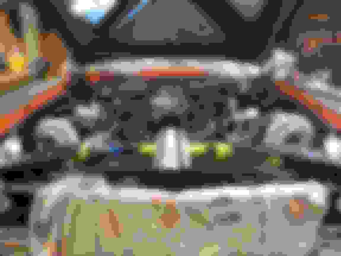
And finally got around to starting on the passenger side pre-turbo hotpipe. Yes, that's some laser alignment going on! Figured it was easiest reference to have once I confirmed that the laser was perpendicular to the center plane of the car via left & right distance measurements from both the firewall and the rad support. I also got the turbo's to the exact same height... 259mm height from the top of the subframe to the oil drain flange surface. Nerd!
I did some cutting and tack welding but ran out of time to tack on my last couple cut bends, but looks like the hot piping appear close to mirrored up until the final 90* bend into the T3 flanges.
I think that with the wastegates up top, the wastegate dump pipes routed near the turbine housing and over the turbine inlet should help mask the remaining asymmetry in the turbine housing mounting area. I also like that both compressor housings will likely have the outlets pointing directly down, which could make them appear "lined up" side to side, in the absence of actual symmetry in the compressor housings.
Are you going to space those fans away from the radiator a bit with a shroud so they can draw through the whole radiator? With fans that big you won't need an engine ; just let them pull you along! A big PWM controller might be needed to tame the hurricane force wind noise.
Are you going to space those fans away from the radiator a bit with a shroud so they can draw through the whole radiator? With fans that big you won't need an engine ; just let them pull you along! A big PWM controller might be needed to tame the hurricane force wind noise.
The core is recessed about 1/2" in from the end tanks, and I built up the thickness another 1/4" on top of the end tanks with protective cardboard layers.. so fans as they sit are about 3/4" off the core! We'll see how the noise is.. I may just have to overcome fan noise with boost whistle ☺ I'm more than happy to sacrifice noise for suction powerrrrrr.
Ahhh.. here's a fun post to wrap up the weekend. I may cut the driver side wastegate hot pipe off and slacken the miter angle on it, to bring the driver side wastegate up a slight amount, currently it's just barely lower than the passenger side wastegate.
I may cut the driver side wastegate hot pipe off and slacken the miter angle on it, to bring the driver side wastegate up a slight amount, currently it's just barely lower than the passenger side wastegate.
You should or it might bug me.. I mean you.. forever!
The symmetry is so so good. So good. I just want to cry it's so beautiful.
Last edited by -TheBandit-; Jan 8, 2018 at 10:44 AM.
Hahaha.. I know, it was buggin me since before I took the pics, alas I ran out of time yesterday or else I would've cut the wastegate tube a bit to "correct" the issue.
I've burned way too many things in that I should have cut and corrected first. I get all excited about having it mocked up and I just want to make it "done", but if you don't fix that kinda stuff it will pop out at you every time you look at it. That's why I rewelded my rear end so many times - it probably would have been okay but I knew that would be in the back of my mind every time I looked at it.
Had a little time off from the car, ended up going to Barrett-Jackson this past weekend as just a fun spectator thing to do.. holy crap, 1000's of cars all so nice, everything is so next-level big and grand and shiny.
I'm still waiting on Precision turbo exhaust flanges+clamps and Precision T3 inlet flanges, but I got other stuff in the meantime to occupy my energy...
I needed some proper hardware for the turbo piping, and thought stainless would be the right ticket. Naturally I wouldn't want just hardware store metric stuff, and opted for ARP just for added strength. I didn't realize that ARP 300 alloy stainless is 170,000psi yield strength which is actually higher than grade 8 bolts. Went with 6pt heads so I can access everything with an open-ended wrench in tight areas if need be.
Here are some M10x1.25 bolts for the turbo flanges...
M10x1.5 bolts for the flanges on the CTS-V exhaust manifolds...
Exhaust manifold studs for the heads...
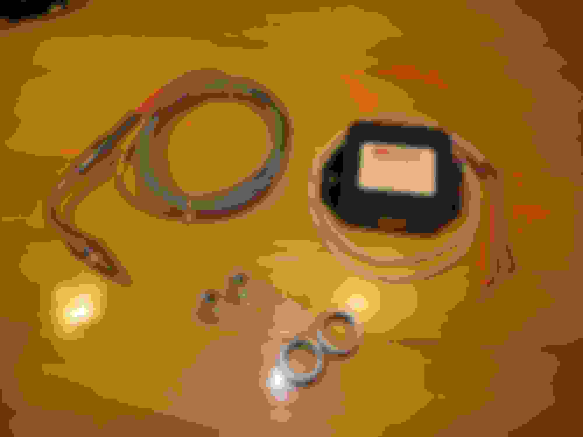
Finally received the back-ordered 64mm Precision BOV... this thing is HUGE! Even the band clamp is black anodized aluminum.. nice!
And an EGT thermocouple to hardwire to the Dominator ecu, which also required a converter to create a 0-5V signal that the Dominator will accept.
I plan to fully log one side of the turbo setup, basically:
1) pre-turbo exhaust temp (stainless K-type thermocouple)
2) pre-turbo exhaust pressure (stainless 3bar sensor after copper pigtail)
3) post-turbo pre-intercooler air pressure (additional sensor needed)
4) post-turbo pre-intercooler air temp (additional sensor needed)
5) post-turbo post-intercooler air pressure (intake MAP sensor)
6) post-turbo post-intercooler air temp (existing IAT sensor)
You are going to love all that data. Are you going to have ambient sensors too? Rotor speed (of the turbo)? You aren't too far off from doing on-engine turbo mapping. #instrumentedtwinturbo
ARP is in my neighborhood. Very simple operation on the surface (blank, forming, thread rolling, heat treat), but they've managed to establish themselves as the defacto brand standard in aftermarket fasteners. Definitely much better material and treat than anything you're going to find at the hardware store. Excessive for just holding parts together, but they sure look nice. I love flange head bolts!
You are going to love all that data. Are you going to have ambient sensors too? Rotor speed (of the turbo)? You aren't too far off from doing on-engine turbo mapping. #instrumentedtwinturbo
Maybe I should measure pre-compressor and post-compressor air temp and turbo shaft speed and estimate efficiency. Haha I think I already have enough to do.
Really annoyed that I've been waiting 3 weeks for the stainless flanges/fab parts from Precision, oh well. This weekend I'll be trying more inner fender progress at the same time as starting to roughly route downpipes.
I also need to finally remove the existing intercooler and start hacking the rad support more to allow airflow for the bigger new C&R radiator core.. but that requires me to remove the grill, trim, and bumper which I've been too lazy to do so far.
The operations ARE simple. It's doing them RIGHT, and consistently, that put them on the map
Yes, I failed to give ARP nearly enough credit in that post above. They have a very well controlled process and the people/family there are top notch. They manufacture right here in the US. They also run a kickass restaurant attached to the Santa Paula site (Hozy's Grill) that's decorated with all kinds of cool race car parts, photos, and memorabilia. I use ARP for all my critical fasteners and eventually I want to swap all the exterior stuff to their pretty stainless stuff.
Joe - Waiting on parts brings the suck. Sucks even more when they finally show up and they aren't what you want/need. I get very lazy too when I'm not working on what I want. There are still lots of things unfinished on my swap that I just never find the time for.
I am sure you know, but make sure you don;t forget to anti-seize the **** out of those stainless bolts! I am using those nifty studs for the exhaust on my Cougar.
Anti-seize is usually a car guy's best friend.. but does anyone have any insight on anti-seize and the insane heat that close to the turbo? I was planning on installing them dry and just not torquing the crap out of them, but instead checking them after initial install and heat cycling to see if they've backed off.
Gas Monkey Built a 6-Wheel Ferrari Testarossa With a Corvette LT4 Engine
Slideshow: The controversial Ferrari F6 swaps its original flat-12 for a Corvette Z06-derived LT4 V8 and sends power to four rear wheels through a custom-built drivetrain.
7 Most Reliable High-Performance Engines GM Has Ever Built
Slideshow:These GM engines didn't just make huge power, they survived abuse, boost, track days, and six-digit mileage with a reputation for refusing to quit.
6 Common C5 Corvette Failures and What's Involved In Repairing Them
Slideshow: From wobbling harmonic balancers to failed EBCMs, these are the issues that define long-term C5 ownership and what repairs typically involve.
Retro Modern Bandit Pontiac Trans AM Comes With Burt Reynolds' Autograph
Slideshow: A modern Camaro transformed into a retro icon, this limited-run "Bandit" build blends nostalgia with brute force in a way few revivals manage.
Top 10 Greatest Cadillac V Series Performance Models Ever, Ranked
Slideshow: Cadillac didn't just crash the high-performance luxury vehicle party, it showed up loud, supercharged, and occasionally a little unhinged...
Coachbuilt N2A Anteros Is an LS2-Powered C6 Corvette In Italian Clothes
Slideshow: A one-off sports car that looks like a vintage Italian exotic-but hides a C6 Corvette underneath-just sold for the price of a new mid-engine Corvette.