
The Turbo Ta Build Thread
 02-13-2011, 02:31 PM
#161

 02-20-2011, 06:25 PM
#162
Another busy weekend of work on the TA has come and gone. This weekend was crazy, but we ended up getting a lot done. We started out Friday going to pick up the new converter from Midwest Converters in Rockford. It looked amazing, but the snout was not the right length. It was the standard TH400 length, but we needed it longer for the LS1 motor. It was a small mistake, but it meant we had to come back the next day after they machined out a new billet cover and put it on the converter. So after that small spot of bad news we got some supplies before heading off to work. I got to work right away finishing up the bumper mounts, so that was out of the way. I added two dzus fasteners to the top side of the bumper near the headlights. It likes to pull down from that area leaving a big gap. The only real problem I had was that the bumper is very thick in that area. The dzus fasteners are intended to go through about 1/8" fiberglass, not 1/4" thick urethane. I had to thin the back side out of the bumper, but I probably should have gone a little further.
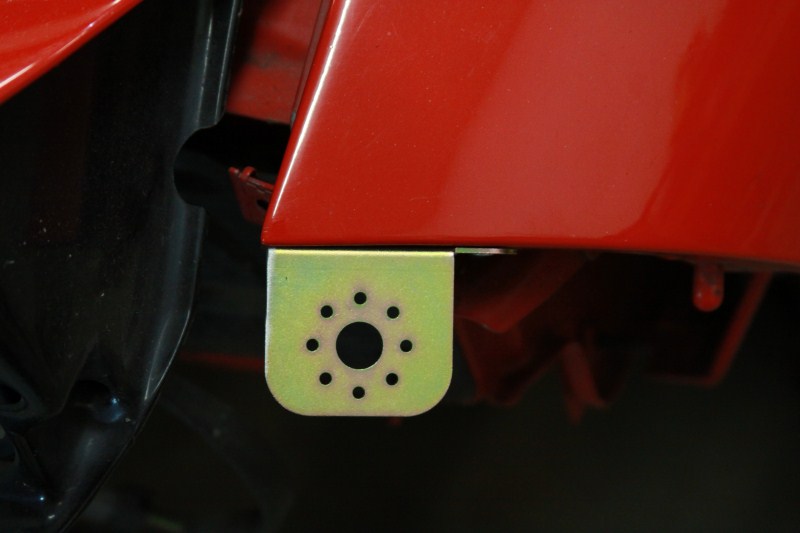
Anyway here you can see the bracket near the driver side headlight (same on passenger side)
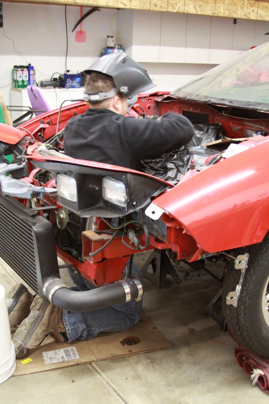
In this picture showing Chris cleaning up the cowl area (that was cut out last weekend), you can see the upper bracket, and the side bracket I made last weekend. I ended up adding a diagonal brace to the bottom corner after this pic was taken, to give it more strength.
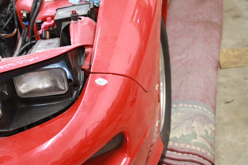
Here is a pic of the driver side fasteners, you can see how the top one pulls the bumper in some.
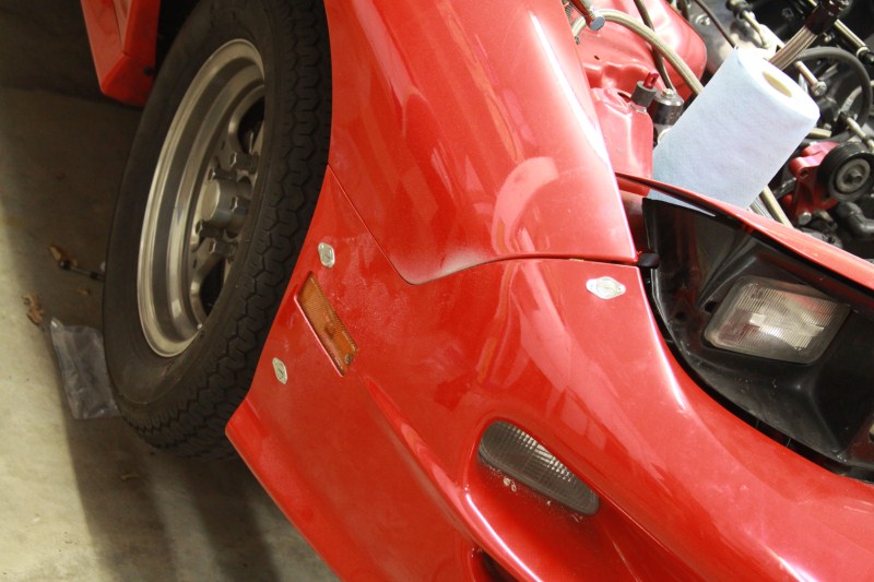
And the passenger side
And the last fastener on the top. I thought about getting rid of this piece all together and making one out of molly, but it wasn't worth all of the work.
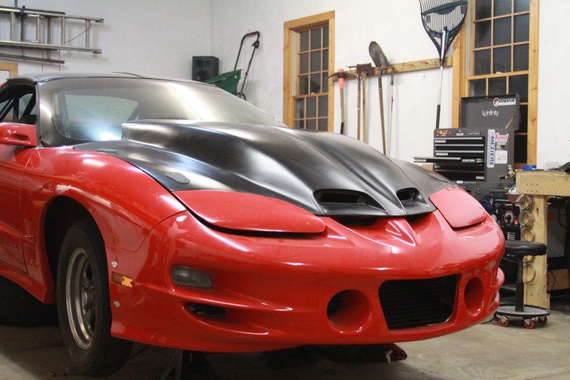
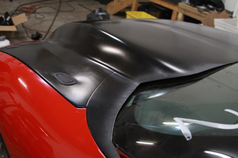
And here is an overall shot of the front end all together. This was after we finished up the rear hood pins, which I will get back too.
So now you have 7 dzus fasteners holding it all in place and thats it. One person can now take the bumper on or off in less than a minute!
While I was working on all of that Chris was having some troubles with some new billet pieces. He bought a billet valley cover plate from AEI CNC to go with the new Edelbrock intake manifold, but when he put it on he noticed that it was covering the cam position sensor. After measuring, comparing, and staring at it we figured out that the holes were drilled the wrong dimension from the front edge. We figured this out at about 9:00 at night and called the place who made the piece. Now only did he answer, he immediately went to a computer waiting for pictures showing what our problem was. Chris was on and off the phone with him for about an hour working out what the exact problem was, so that when the new piece is made on Monday it is 100% perfect. The customer service from AEI is as top notch as it gets!
While we are on the topic of cam position sensors, some of you may remember that we have had problems with them. We have checked every possible thing trying to determine why they go bad so quickly. While everything was apart Chris was able to stick his head over the hole the cam position sensor sits in to check the machining on the cam. That all checked out, as did everything else, so a new sensor will go in again and we will see what happens.
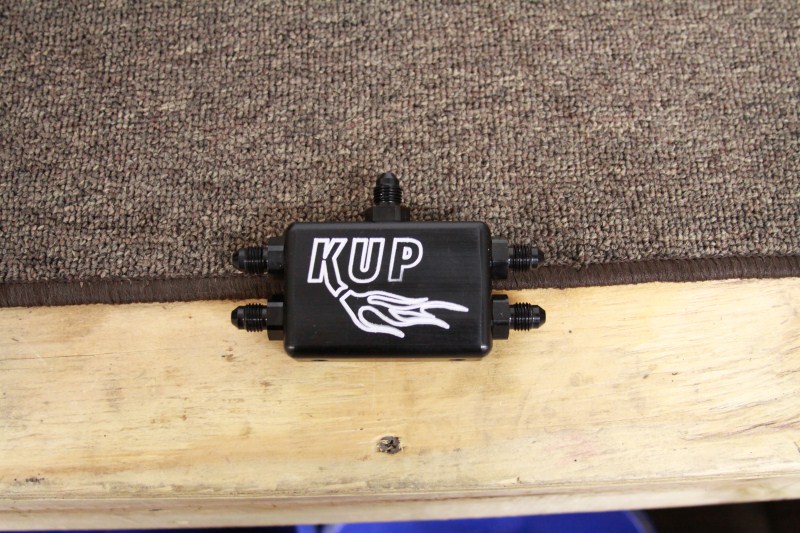
After all that was figured out, he moved on to laying out the new Kurt Urban water vapor set up. Not only does it look fantastic, it should work much better than the factory set up.
Here is a couple of pics of it
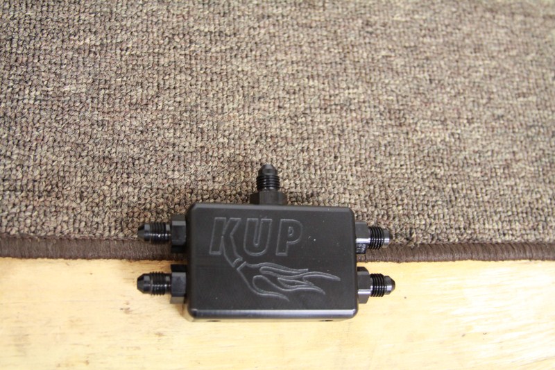
Other side
One of the block adapters
And some overall shots Chris took
Chris also made up a mounting bracket for the block, but needs the new valley cover to install it.
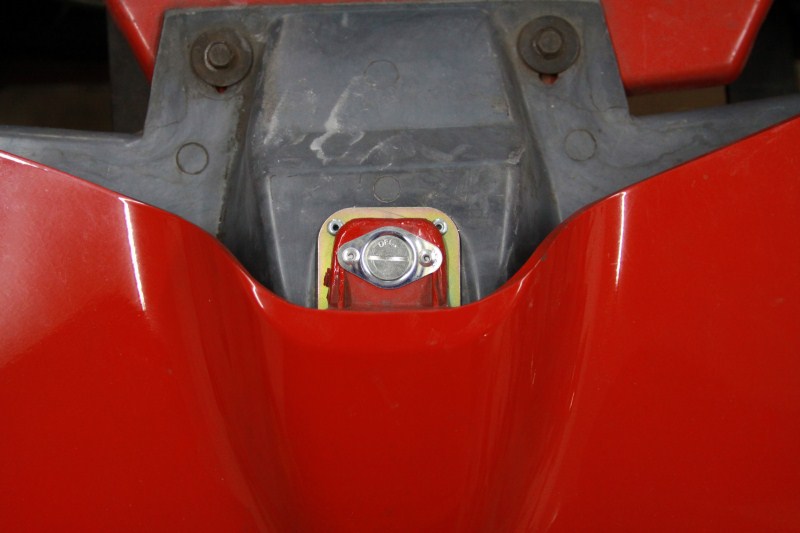
Back on to the hood read quick. I had some spacers made up for the rear pins since they wouldn't reach. They are just some 2" pieces of steel drilled through and tapped so a bolt from the bottom holds them in place.
Simple yet effective. And here is the drivers rear pin all finished
Saturday!
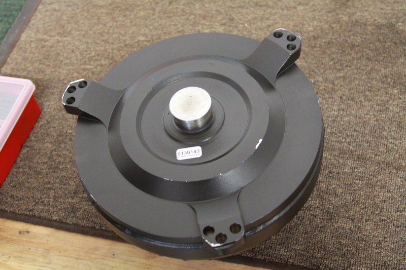
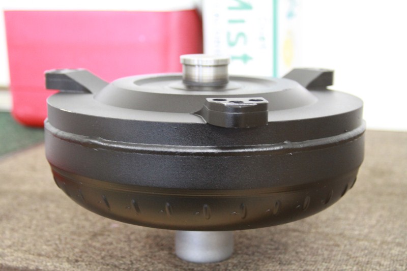
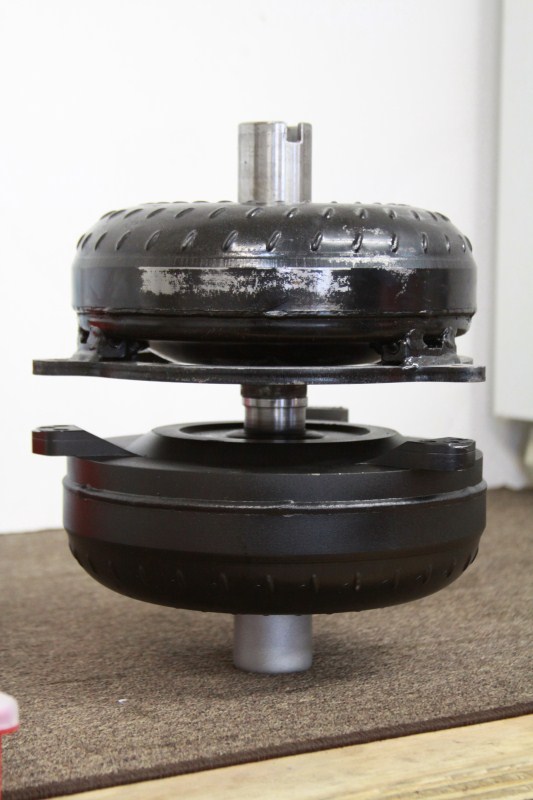
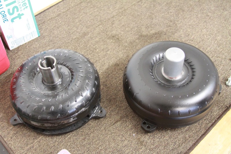
We started out Saturday morning back at Midwest converters to pick up the new new converter. What a beautiful piece it is too!! Ill just let the pictures speak for them selves.
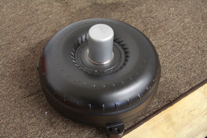
And compared to the old PTC unit that was on the car.
After leaving Midwest converters we stopped for supplies again, and then went back to install the converter and trans. While Chris got started on that, I figured I can get working on the upper inter cooler piping since the intake was still on the motor. So I threw the new throttle body on, and started cutting.
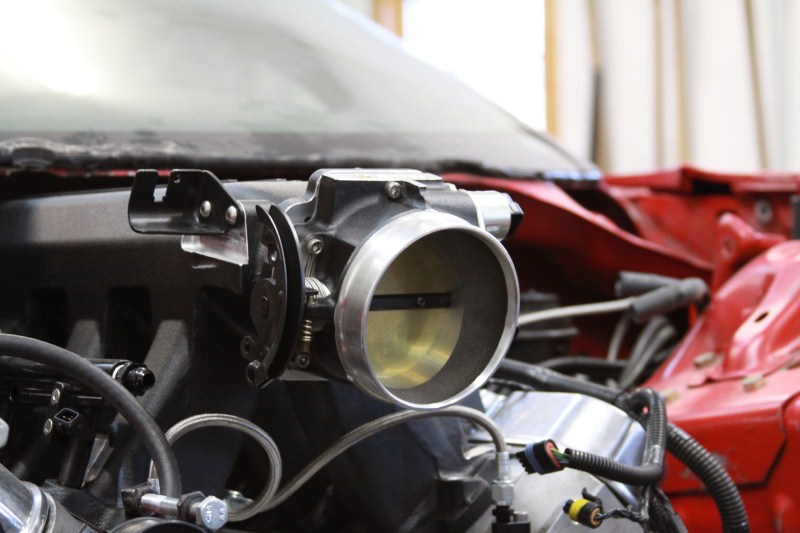
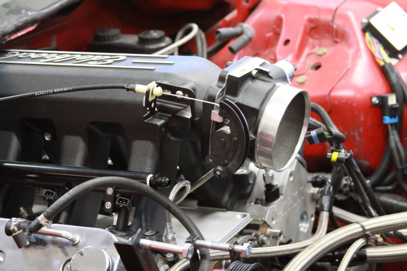
Here are a couple pics of the 90mm Edelbrock throttle body. This first one you can see the factory throttle cable bracket, which does not work.
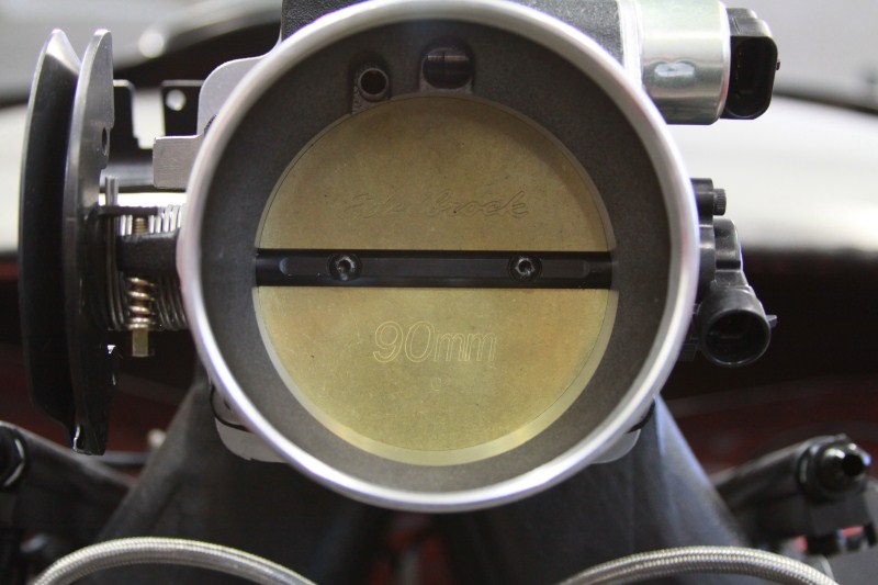
Matching powder coat
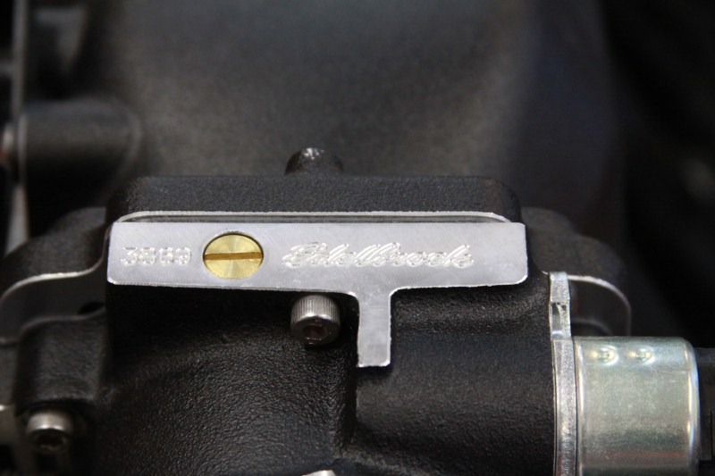
Here you can see the supplied cable bracket which I will modify next week Also you can see the fuel rail mounts I had made up at work. I will get more pics of them, and the plug that was made next week.
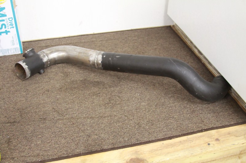
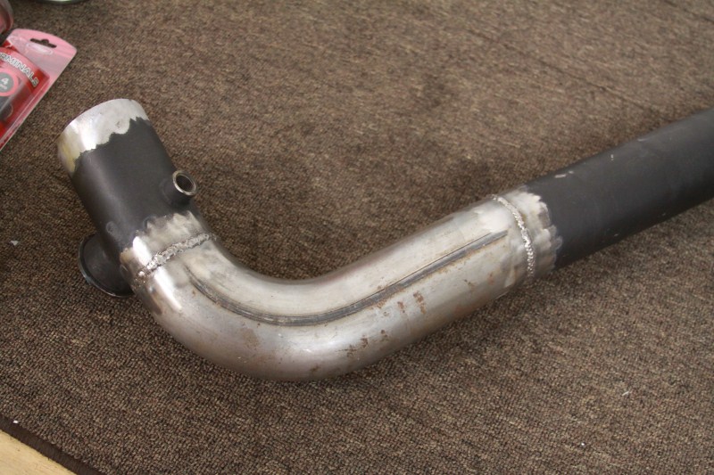
Here is the newly modified (AGAIN) upper inter cooler pipe. I had to make up an angle by cutting it into the pipe which is not my preferred method, but I was working with what I had.
While I was working on this, Chris discovered that the converter needed different bolts than the last one. So another run back to Rockford for bolts (this was the third trip of the weekend for those counting). We got back and Chris started on trimming the trans and shield to fit. Again, while he was working on that I decided to plug the breather holes on the valve covers since we don't need them. I have only welded aluminum once before, but it went OK I guess.
Here is the result
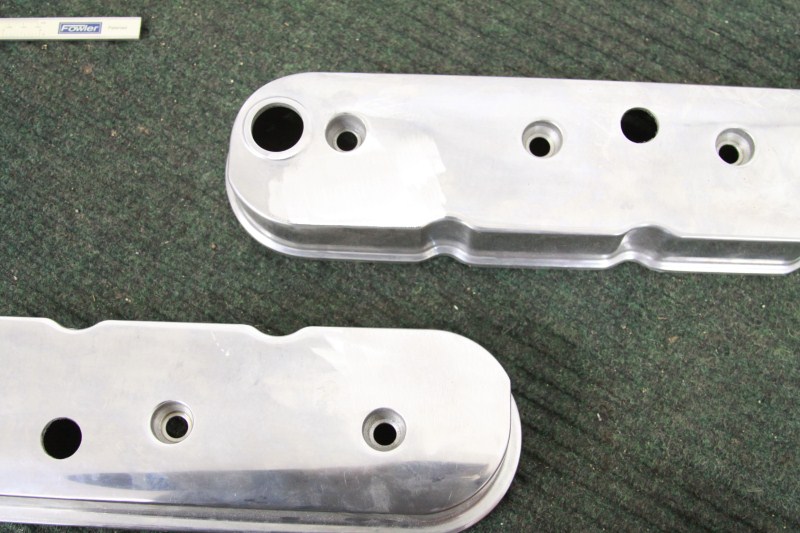
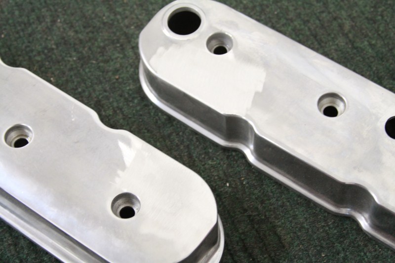
Now they need to get cleaned up and powder coated!
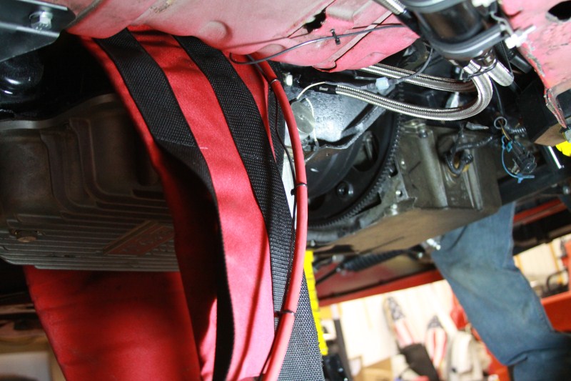
And again, while I was doing that Chris figured out that the bolts that came with the trans shield would not work. So at 8:30 at night we made ANOTHER run to Rockford for bolts! We figured that 60mm long would work just fine, and of course they didn't have any that size. Chris grabbed some 50mm bolts and I told him they would be too short, and to get the 75mm ones instead. We get back to the house and figure out that the 75mm is too long, the threaded part was to long, and the non threaded shoulder was also too long. Double fail!! We then figured out that he 50mm (though not ideal) would have worked!! This trans just did not want to go in this weekend! I started digging around in the junk drawer and found a bag of brand new 55mm long M10x1.5 grade 10.8 bolts!!! SUCCESS finally That is when the battle begun! I found the bolts at around 9:30PM or so, we finished up about 2:00AM! The trans shield was such a pain in the ***, but its all in there now, and here is the proof.
Well that is all for this weekend. Next weekend should see the intake all buttoned up, the turbo back on, and possibly the car running! Thanks again for following along!
Sean
Anyway here you can see the bracket near the driver side headlight (same on passenger side)
In this picture showing Chris cleaning up the cowl area (that was cut out last weekend), you can see the upper bracket, and the side bracket I made last weekend. I ended up adding a diagonal brace to the bottom corner after this pic was taken, to give it more strength.
Here is a pic of the driver side fasteners, you can see how the top one pulls the bumper in some.
And the passenger side
And the last fastener on the top. I thought about getting rid of this piece all together and making one out of molly, but it wasn't worth all of the work.
And here is an overall shot of the front end all together. This was after we finished up the rear hood pins, which I will get back too.
So now you have 7 dzus fasteners holding it all in place and thats it. One person can now take the bumper on or off in less than a minute!
While I was working on all of that Chris was having some troubles with some new billet pieces. He bought a billet valley cover plate from AEI CNC to go with the new Edelbrock intake manifold, but when he put it on he noticed that it was covering the cam position sensor. After measuring, comparing, and staring at it we figured out that the holes were drilled the wrong dimension from the front edge. We figured this out at about 9:00 at night and called the place who made the piece. Now only did he answer, he immediately went to a computer waiting for pictures showing what our problem was. Chris was on and off the phone with him for about an hour working out what the exact problem was, so that when the new piece is made on Monday it is 100% perfect. The customer service from AEI is as top notch as it gets!
While we are on the topic of cam position sensors, some of you may remember that we have had problems with them. We have checked every possible thing trying to determine why they go bad so quickly. While everything was apart Chris was able to stick his head over the hole the cam position sensor sits in to check the machining on the cam. That all checked out, as did everything else, so a new sensor will go in again and we will see what happens.
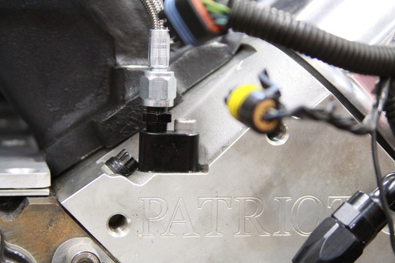
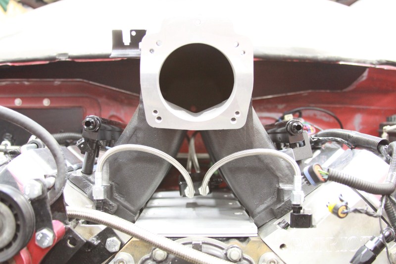
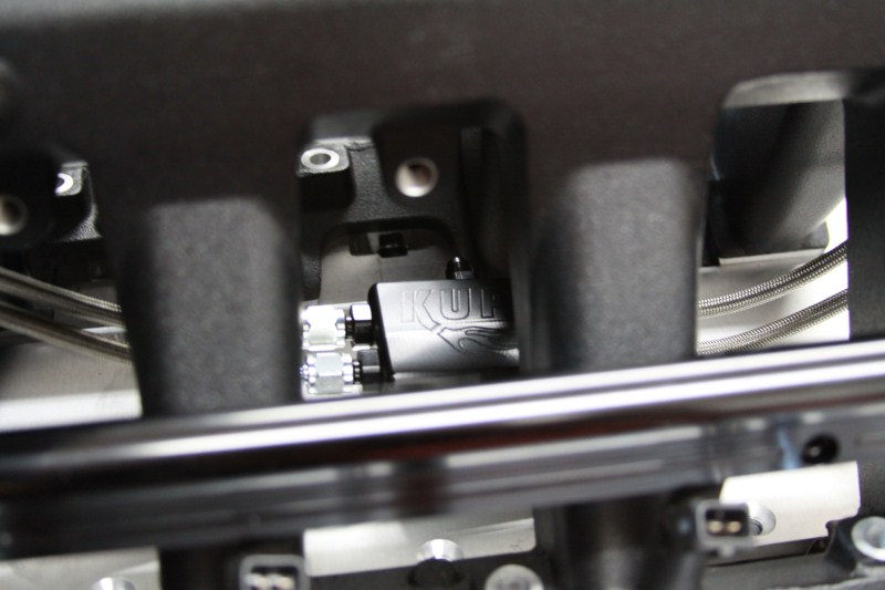
After all that was figured out, he moved on to laying out the new Kurt Urban water vapor set up. Not only does it look fantastic, it should work much better than the factory set up.
Here is a couple of pics of it
Other side
One of the block adapters
And some overall shots Chris took
Chris also made up a mounting bracket for the block, but needs the new valley cover to install it.
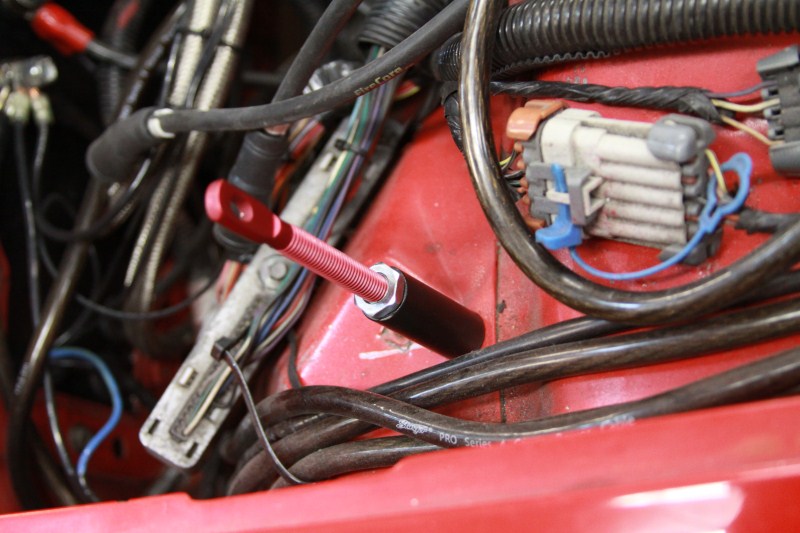
Back on to the hood read quick. I had some spacers made up for the rear pins since they wouldn't reach. They are just some 2" pieces of steel drilled through and tapped so a bolt from the bottom holds them in place.
Simple yet effective. And here is the drivers rear pin all finished
Saturday!
We started out Saturday morning back at Midwest converters to pick up the new new converter. What a beautiful piece it is too!! Ill just let the pictures speak for them selves.
And compared to the old PTC unit that was on the car.
After leaving Midwest converters we stopped for supplies again, and then went back to install the converter and trans. While Chris got started on that, I figured I can get working on the upper inter cooler piping since the intake was still on the motor. So I threw the new throttle body on, and started cutting.
Here are a couple pics of the 90mm Edelbrock throttle body. This first one you can see the factory throttle cable bracket, which does not work.
Matching powder coat
Here you can see the supplied cable bracket which I will modify next week
Also you can see the fuel rail mounts I had made up at work. I will get more pics of them, and the plug that was made next week.Here is the newly modified (AGAIN) upper inter cooler pipe. I had to make up an angle by cutting it into the pipe which is not my preferred method, but I was working with what I had.
While I was working on this, Chris discovered that the converter needed different bolts than the last one. So another run back to Rockford for bolts (this was the third trip of the weekend for those counting). We got back and Chris started on trimming the trans and shield to fit. Again, while he was working on that I decided to plug the breather holes on the valve covers since we don't need them. I have only welded aluminum once before, but it went OK I guess.
Here is the result
Now they need to get cleaned up and powder coated!
And again, while I was doing that Chris figured out that the bolts that came with the trans shield would not work. So at 8:30 at night we made ANOTHER run to Rockford for bolts! We figured that 60mm long would work just fine, and of course they didn't have any that size. Chris grabbed some 50mm bolts and I told him they would be too short, and to get the 75mm ones instead. We get back to the house and figure out that the 75mm is too long, the threaded part was to long, and the non threaded shoulder was also too long. Double fail!! We then figured out that he 50mm (though not ideal) would have worked!! This trans just did not want to go in this weekend! I started digging around in the junk drawer and found a bag of brand new 55mm long M10x1.5 grade 10.8 bolts!!! SUCCESS finally
That is when the battle begun! I found the bolts at around 9:30PM or so, we finished up about 2:00AM! The trans shield was such a pain in the ***, but its all in there now, and here is the proof.Well that is all for this weekend. Next weekend should see the intake all buttoned up, the turbo back on, and possibly the car running! Thanks again for following along!
Sean
02-20-2011, 07:47 PM
#163
 : I'm sorry you don't have a faster car
 02-21-2011, 01:33 PM
#169
11 Second Club
iTrader: (103)
Join Date: Aug 2005
Location: South of West Point Iowa
Posts: 2,633
Likes: 0
Received 1 Like
on
1 Post

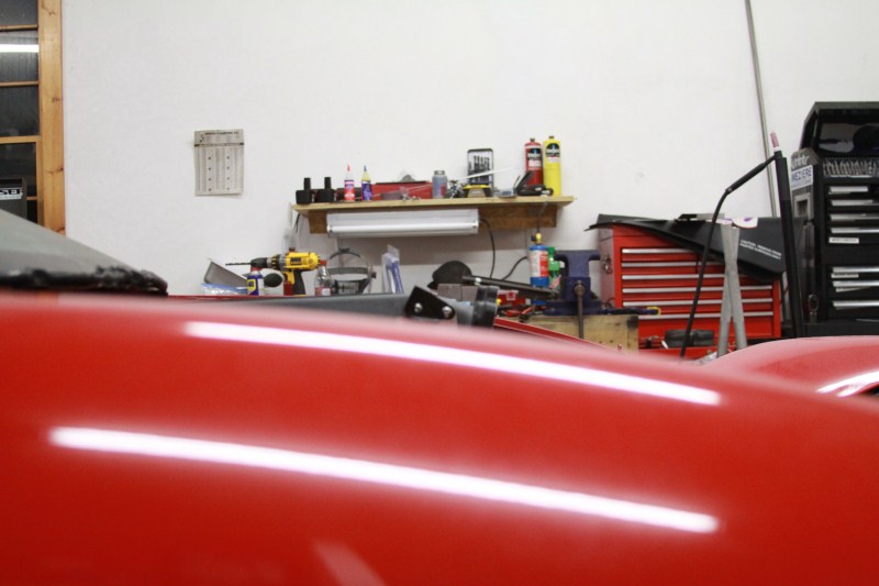
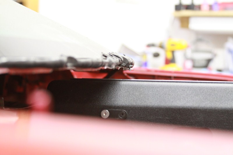
Broke/Sideways... What are you doing to prevent the hood from vibrating against the windshield? I saw this shot and was reminded that my own Sunoco (against the windshield) has a nasty vibration at anything over 50mph... and I kinda like to go over 50 at the track... I'm planning on adding a center dzus & little tower for the mount. I've still got the cowl for the windshield under the hood, but like you, have tossed the wipers/motors/plastics.
Thanks,
D
Thanks,
D
Originally Posted by Broke
02-22-2011, 05:02 PM
#171
Broke/Sideways... What are you doing to prevent the hood from vibrating against the windshield? I saw this shot and was reminded that my own Sunoco (against the windshield) has a nasty vibration at anything over 50mph... and I kinda like to go over 50 at the track... I'm planning on adding a center dzus & little tower for the mount. I've still got the cowl for the windshield under the hood, but like you, have tossed the wipers/motors/plastics.
Thanks,
D
Thanks,
D
Sean
02-23-2011, 07:49 PM
#177
Looking good!
Looking at those dzus fasteners located on the sides going verticle...do you have any more pics as to how you mounted them? Also are 4 hood pins all you're going with? I ask because I thought 6 was the magic number for pins? I'm not sure but wondering
Looking at those dzus fasteners located on the sides going verticle...do you have any more pics as to how you mounted them? Also are 4 hood pins all you're going with? I ask because I thought 6 was the magic number for pins? I'm not sure but wondering
02-23-2011, 08:51 PM
#178
Ill get more pics of the side brackets soon. I need to take them off, clean up the not so nice welds, sand blast them and get a coat of paint on them. THEN Ill have some pics
Yes we are only going with 4 pins, if it looks like we will have problems we will reconsider.
Thanks,
Sean
Yes we are only going with 4 pins, if it looks like we will have problems we will reconsider.
Thanks,
Sean
02-23-2011, 08:58 PM
#179
I write checks with my mouth that my ass can't cash
iTrader: (7)

Join Date: Oct 2009
Posts: 948
Likes: 0
Received 0 Likes
on
0 Posts
iv been wondering, is the 4-pins enough ?, i am getting a sonoco pin on for my camaro in the next few days and was thinking of just running the 4 hood pins...but im worried it will flex and blow around with just 4 pins in it....