Paxton novi 2000 disassembly
Thread Starter
Teching In
Joined: Aug 2009
Posts: 8
Likes: 0
From: Princeton TX
** Note at this time i do not have TORQUE SPECS for re-assembly. You may click on the photos for a larger image. THIS ARTICLE IS NOT FULLEY COMPELTE, and does not include re-assembly at this time**
*** UPDATE! May 10,2010 I have changed my name to Blown_RT, any questions can be directed towards my new user name. "
Hi, my supercharger sounded like it spun a bearing about a year ago. I parked the truck removed the charger and was going to send it off. Paxton would not warrenty it, and i didnt want to spend shipping and labor for them to tell me its not repairable or extremely expensive. It has sat for a year, and the truck hasnt moved so i decided to go ahead and tear into it. ( why not, its a paper weight right now) I discovered there is very little info on this, so i decided to go ahead and wright and article with step by step instructions and photos to help the next guy out. I did find a good reference article with part numbers for bearings and seals at http://www.superchargerhelp.com/show...highlight=seal
written by ROADW3. I would like to thank him for this since it was the most comprehensive articel out there. As a disclaimer i am not a certified paxton employee, nor am i an expert. I will tell you what i have been told " Take it to the professionals and let them do it" If your gonna do it yourself, this should give you and idea of whats going on. I have found that it was not near as difficult as i was expecting, and i was able to do it with simple hand tools. ( so far at least)
Assuming the head unit is off the truck, lets get to it.
Step 1. We are going to start by removing the impeller nut. THIS IS A REVERSE THREAD Do this now while the pulley is still on so you have some way of stopping the impeller from turning. Before removing check to see if the black sharpie mark is aligned with the nut and impeller. ( this is something the pros do and could give you more info later on if needed, this is checking to see if the impeller or nut has spun.) ** note: i did not do this, found out about it later**
Holding the pulley with a rag, using a 14mm nut and an impact turned down, remove the nut. REMEMBER IT IS A REVERSE THREAD!!
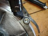
Step 2. Turn the blower over and remove the idler arm by removing the bolt in the center. Once this is done, slightly lift the arm up paying attention to the position of the alignment pin and its correct hole. The arm should not spring on you.
Step 3. Remove the idler arm base. This has to be removed to access the 2 allen bolts in the gear case cover. Mark the base with a sharpie for its correct location durring assembly, and remove the 2 allen bolts.
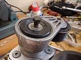
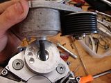
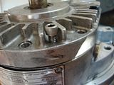
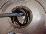
Step 4. Now we will remove the pulley. In order to do this you will have to remove the grey center cap. ( Doing this VOIDS any warrenty on the charger, as the cap says) To remove it, you will need to pry apart the metal ring at the base of the cap. Prying between the grey cap and the black metal ring.Once the ring is away, you can pry the grey cap up leaving the metal ring attached to the bolt and washer underneith.
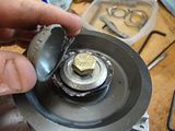
Once the cap is removed, remove the bolt in the center of the pulley. The pulley should then slide off the shaft. A puller is not needed. PAY ATTENTION to the keys inside the pulley, making sure not to lose them.
Underneith the pulley is 2 washers, remove these from the shaft.
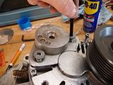
Now that the impeller nut, idler arm and base, and pulley are off, we can remove the gear case cover. Do this by cutting the safety wire on the 2 allens. I would star by removing those 2 allens first, since for some reason they were the hardest to remove for me. ( one did require and EZ out after i rounded it)
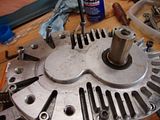
once the bolts are out, turn the charger so that the shaft is closest to you. Note that only 2 holes in the cover are threaded. Using one of the allens thread it into this hole, untill it makes contact with the base. ( the threaded hole in the cover goes all the way through to the solid base on the gear box.)
Now Take your 2 screws from the IDLER ARM BASE PLATE, and thread them back into the cover were they were orignally located. This will give you something to pull on, without having to drive a screwdriver between the cases. ( there is an O-RING inside, and you DO NOT want to scratch the seat between the cover and gearbox.)
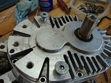
**There is 2 alignment pins between the gear box and cover
Now starting with the shaft end, slowly tighten the allen you threaded into the cover. The cover should start to rise off of the gear box. THANKS ROADW3 for this tip Once there is a slight gap STOP!
Move over to the idler arm side, and gently pull on your to temp. allen bolts. ( I had to lightly tap on the cover with a rubber hammer, while pulling up) Once the seat is up, move back to the shaft side, and tighten a little more. WORK SLOWLY so you do not warp the cover or damage the shaft. Continue this untill the alignment pins are clear and you can get your fingers or another soft object in between the cover and gear box.
Once the cover is lose, be careful. The pulley shaft is held in by the cover and the gearbox. It may stick to the cover, coming lose at the gear box side. You dont want to drop it by mistake.
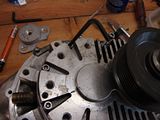
Remove the cover from the gearbox and shaft.
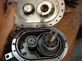
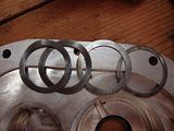
Notice that there are some spring washers inside the cover, ( they may of fell out.) these load the bearing on the impeller shaft.
part 3.
Notice that there are some spring washers inside the cover, ( they may of fell out.) these load the bearing on the impeller shaft.
all to gether there are 2 sping washers and 2 flat washers. The flat washers go closest to the cover.
*** UPDATE! May 10,2010 I have changed my name to Blown_RT, any questions can be directed towards my new user name. "
Hi, my supercharger sounded like it spun a bearing about a year ago. I parked the truck removed the charger and was going to send it off. Paxton would not warrenty it, and i didnt want to spend shipping and labor for them to tell me its not repairable or extremely expensive. It has sat for a year, and the truck hasnt moved so i decided to go ahead and tear into it. ( why not, its a paper weight right now) I discovered there is very little info on this, so i decided to go ahead and wright and article with step by step instructions and photos to help the next guy out. I did find a good reference article with part numbers for bearings and seals at http://www.superchargerhelp.com/show...highlight=seal
written by ROADW3. I would like to thank him for this since it was the most comprehensive articel out there. As a disclaimer i am not a certified paxton employee, nor am i an expert. I will tell you what i have been told " Take it to the professionals and let them do it" If your gonna do it yourself, this should give you and idea of whats going on. I have found that it was not near as difficult as i was expecting, and i was able to do it with simple hand tools. ( so far at least)
Assuming the head unit is off the truck, lets get to it.

Step 1. We are going to start by removing the impeller nut. THIS IS A REVERSE THREAD Do this now while the pulley is still on so you have some way of stopping the impeller from turning. Before removing check to see if the black sharpie mark is aligned with the nut and impeller. ( this is something the pros do and could give you more info later on if needed, this is checking to see if the impeller or nut has spun.) ** note: i did not do this, found out about it later**
Holding the pulley with a rag, using a 14mm nut and an impact turned down, remove the nut. REMEMBER IT IS A REVERSE THREAD!!

Step 2. Turn the blower over and remove the idler arm by removing the bolt in the center. Once this is done, slightly lift the arm up paying attention to the position of the alignment pin and its correct hole. The arm should not spring on you.


Step 3. Remove the idler arm base. This has to be removed to access the 2 allen bolts in the gear case cover. Mark the base with a sharpie for its correct location durring assembly, and remove the 2 allen bolts.


Step 4. Now we will remove the pulley. In order to do this you will have to remove the grey center cap. ( Doing this VOIDS any warrenty on the charger, as the cap says) To remove it, you will need to pry apart the metal ring at the base of the cap. Prying between the grey cap and the black metal ring.Once the ring is away, you can pry the grey cap up leaving the metal ring attached to the bolt and washer underneith.


Once the cap is removed, remove the bolt in the center of the pulley. The pulley should then slide off the shaft. A puller is not needed. PAY ATTENTION to the keys inside the pulley, making sure not to lose them.

Underneith the pulley is 2 washers, remove these from the shaft.

Now that the impeller nut, idler arm and base, and pulley are off, we can remove the gear case cover. Do this by cutting the safety wire on the 2 allens. I would star by removing those 2 allens first, since for some reason they were the hardest to remove for me. ( one did require and EZ out after i rounded it)

once the bolts are out, turn the charger so that the shaft is closest to you. Note that only 2 holes in the cover are threaded. Using one of the allens thread it into this hole, untill it makes contact with the base. ( the threaded hole in the cover goes all the way through to the solid base on the gear box.)

Now Take your 2 screws from the IDLER ARM BASE PLATE, and thread them back into the cover were they were orignally located. This will give you something to pull on, without having to drive a screwdriver between the cases. ( there is an O-RING inside, and you DO NOT want to scratch the seat between the cover and gearbox.)

**There is 2 alignment pins between the gear box and cover
Now starting with the shaft end, slowly tighten the allen you threaded into the cover. The cover should start to rise off of the gear box. THANKS ROADW3 for this tip Once there is a slight gap STOP!

Move over to the idler arm side, and gently pull on your to temp. allen bolts. ( I had to lightly tap on the cover with a rubber hammer, while pulling up) Once the seat is up, move back to the shaft side, and tighten a little more. WORK SLOWLY so you do not warp the cover or damage the shaft. Continue this untill the alignment pins are clear and you can get your fingers or another soft object in between the cover and gear box.
Once the cover is lose, be careful. The pulley shaft is held in by the cover and the gearbox. It may stick to the cover, coming lose at the gear box side. You dont want to drop it by mistake.
Remove the cover from the gearbox and shaft.

Notice that there are some spring washers inside the cover, ( they may of fell out.) these load the bearing on the impeller shaft.
part 3.
Notice that there are some spring washers inside the cover, ( they may of fell out.) these load the bearing on the impeller shaft.

all to gether there are 2 sping washers and 2 flat washers. The flat washers go closest to the cover.

Last edited by iclimbthings; May 11, 2010 at 09:18 PM.
Thread Starter
Teching In
Joined: Aug 2009
Posts: 8
Likes: 0
From: Princeton TX
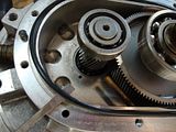
Step 7. Remove the pulley shaft. Mine came out quite easily with a little pulling with the hand. Be carefull that the gear on the shaft clears the bearing on the impeller shaft. You will have to slightly tilt the shaft, once it is free, to remove it.
Once the pulley shaft is removed, remove the sping washer from the gear box.
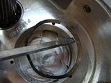
Remove the o-ring from the gear box cover.
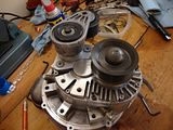
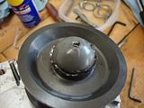
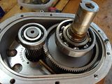
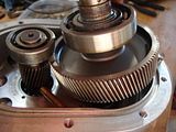
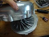
Step 8. With the cover, pulley shaft assembly, washers and o-rings out, we can now move on to the volute. ( snail looking back cover)
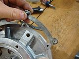
Mark the brackets with a sharpie on each side so that you will know exactly were they go when you want to reassemble the blower. Also Mark a few alinment marks on the VOLUTE AND GEARBOX, so you know the exact position the volute goes in when reinstalled. It is a circle and can possibly be put on at the wrong angle.
Remove the brackets and allen bolts from the volute
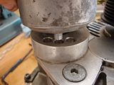
Once all are removed, position the blower so that you can lightly tap on the volute with a rubber hammer. Evenly tapping all the way around the volute should come off.
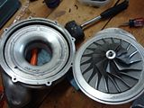
At this point you should now have the gearbox, impeller, and shaft left. In order to remove the shaft, you must first remove the impeller. Once the impeller is removed, the shaft goes out THROUGH THE GEARBOX. I am stopping this here for now, as i have not removed the impeller yet, and am working on the correct way to do so.
As for the bearings, the bearings are pressed onto the shaft, and a local machine shop should be able to do this for you.
PART NUMBERS ** Taken from ROADW3 post.
" Main input shaft seal = CR (chicago rawhide) 9838 or 9837 or the Federal Mogul 472311
all are the same seal. The 9838 and 9837 do have a difference in the way the lip is, but they are both used for the same applications. You can check them out at www.chicago-rawhide.com. The measurements for this seal are 1.00 x 1.437 x 0.250."
"Large main drive bearings = 1 x ME1206 Thrust"
"The two smaller impeller bearings = 2 x 203HX96 Barden Thrust"
"Anyways, I stopped by the parts store today. What do you know, everything was in stock. Yeah, even those custom made seals Paxton was telling me about. No other place carries them.. Whatever. I picked up the front main seal and the front oil seal. The oil seal is a CR (chicago rawhide) 9838. It is a rubber seal with a metal case. Cost, are you sitting down, 3 dollars. The main seal, it is just a large "O" ring. Cost, 75 cents."
Other useful links ROADW3 post at ( has great info on parts)
http://www.superchargerhelp.com/show...highlight=seal
and mustang magazines article at. ( has some useful photos)
http://www.mustang50magazine.com/tec...ild/index.html
Thanks alot to ROADW3, i really appreicate you getting back to me, and your efforts of being the first to tear one of these down ( at least online.)
I will be talking to PAXTON and a few other supercharger shops to find out the correct way to remove the impeller, and will continue this article towards the end of the week. Hopefully it gives the next guy at least some idea of what hes getting into. .
additional photos
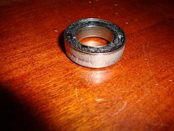
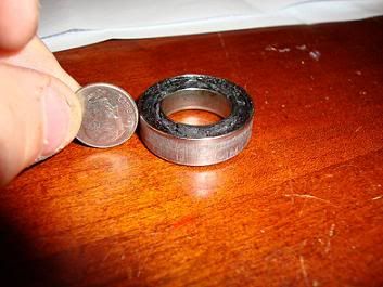
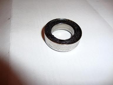
I personally found the problem with my blower was that the impeller bearing came apart. The ***** inside the bearing are held together with a plastic-like cage which came apart losing a few of the *****. ( I am assuming they are now in the bottom of my oil pan, since the only place for them to go is out the outflow oil tube on the charger. )
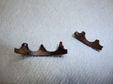
This caused a loud grinding noise, suddenly as i was driving down the road at 55mph with cruise set. It went from fine to bad instantly.
I am including a few other photos for now for reference.
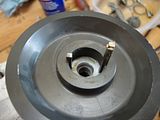
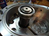
 Pulley shaft gearcase side bearing.
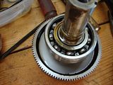 Pulley shaft, gearbox cover side bearing
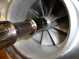
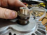
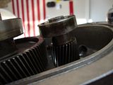
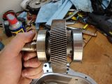
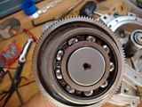
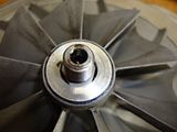
 Impeller shaft gear and bearing
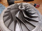 Impeller
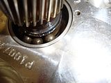
 What appers to be some form of key inside the impeller. It form a triangle just below the threads.
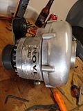
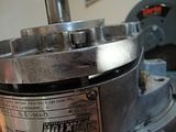
Charger before disassembley


Once the pulley shaft is removed, remove the sping washer from the gear box.


Remove the o-ring from the gear box cover.

Step 8. With the cover, pulley shaft assembly, washers and o-rings out, we can now move on to the volute. ( snail looking back cover)
Mark the brackets with a sharpie on each side so that you will know exactly were they go when you want to reassemble the blower. Also Mark a few alinment marks on the VOLUTE AND GEARBOX, so you know the exact position the volute goes in when reinstalled. It is a circle and can possibly be put on at the wrong angle.

Remove the brackets and allen bolts from the volute

Once all are removed, position the blower so that you can lightly tap on the volute with a rubber hammer. Evenly tapping all the way around the volute should come off.


At this point you should now have the gearbox, impeller, and shaft left. In order to remove the shaft, you must first remove the impeller. Once the impeller is removed, the shaft goes out THROUGH THE GEARBOX. I am stopping this here for now, as i have not removed the impeller yet, and am working on the correct way to do so.
As for the bearings, the bearings are pressed onto the shaft, and a local machine shop should be able to do this for you.
PART NUMBERS ** Taken from ROADW3 post.
" Main input shaft seal = CR (chicago rawhide) 9838 or 9837 or the Federal Mogul 472311
all are the same seal. The 9838 and 9837 do have a difference in the way the lip is, but they are both used for the same applications. You can check them out at www.chicago-rawhide.com. The measurements for this seal are 1.00 x 1.437 x 0.250."
"Large main drive bearings = 1 x ME1206 Thrust"
"The two smaller impeller bearings = 2 x 203HX96 Barden Thrust"
"Anyways, I stopped by the parts store today. What do you know, everything was in stock. Yeah, even those custom made seals Paxton was telling me about. No other place carries them.. Whatever. I picked up the front main seal and the front oil seal. The oil seal is a CR (chicago rawhide) 9838. It is a rubber seal with a metal case. Cost, are you sitting down, 3 dollars. The main seal, it is just a large "O" ring. Cost, 75 cents."
Other useful links ROADW3 post at ( has great info on parts)
http://www.superchargerhelp.com/show...highlight=seal
and mustang magazines article at. ( has some useful photos)
http://www.mustang50magazine.com/tec...ild/index.html
Thanks alot to ROADW3, i really appreicate you getting back to me, and your efforts of being the first to tear one of these down ( at least online.)
I will be talking to PAXTON and a few other supercharger shops to find out the correct way to remove the impeller, and will continue this article towards the end of the week. Hopefully it gives the next guy at least some idea of what hes getting into. .
additional photos
I personally found the problem with my blower was that the impeller bearing came apart. The ***** inside the bearing are held together with a plastic-like cage which came apart losing a few of the *****. ( I am assuming they are now in the bottom of my oil pan, since the only place for them to go is out the outflow oil tube on the charger. )


This caused a loud grinding noise, suddenly as i was driving down the road at 55mph with cruise set. It went from fine to bad instantly.
I am including a few other photos for now for reference.
 Pulley shaft gearcase side bearing.
 Pulley shaft, gearbox cover side bearing
 Impeller shaft gear and bearing
 Impeller
 What appers to be some form of key inside the impeller. It form a triangle just below the threads. Charger before disassembley
9 Second Club
Joined: Nov 2003
Posts: 13,616
Likes: 185
From: Norn Iron
Cant help specifically on this, but I took my Vortech apart a couple of years ago.
From memory, I just pressed the high speed shaft out of the impellor. There may or may not be some useful info here
https://ls1tech.com/forums/forced-in...h-repairs.html
I can only presume I used an Allen key or centre punch to push through the impellor. I think it took a fair bit of effort too...both removal and refitting ( ie you need a hydraulic press. I actually bought one for doing this job in the first place ! ) The shaft itself is just smooth and the impellor is just a press fit. I have thought to alignment for balancing, but came to the conclusion no such alignment would be necessary.
I would also say to refit the impellor before building up the gearbox casing, so you can support the lower side of the high speed shaft when pressing the impellor back on.
I had trouble sourcing bearings. I finally ended up with some Nachi bearings. These were by far the best quality I could source. I only replaced the low speed bearings. My high speed ones were fine.
Given the speeds involved, ensure any bearings are a high precision matched pair.
9 Second Club
Joined: Nov 2003
Posts: 13,616
Likes: 185
From: Norn Iron
My unit appeared to be all metric in terms of bearings, dont know if yours are the same or not. I'd imagine they'd be very close. My original bearings did have Vortech embossed on them, although I doubt Vortech actually make them.
I bought these bearings. They come boxed as a precision matched pair of bearings.

Obviously the larger 7205's are the low speed, and the 7203 the high speed. These Nachi's had the highest spec of any bearing I could find, and the highest speed rating.
The low speed are within tolerance to the speeds I'd be seeing, of 20,000rpm+
The high speeds were a problem. I couldnt find any bearing anywhere rated to the speeds actually seen. So I just assume Vortech overspin the bearings by quite a margin. There is no way on this earth, that Vortech's own bearings are so much superior to anything else. This shaft would see some 3-4x the speed rating of any bearing I could find.
However, as my high speed bearings were fine, I did not replace them.
I did not replace the oil seal behind the impellor either, it was ok, so didnt see any point. Also as it wasnt a conventional style oil seal, I had no idea how to get a replacement. If it aint broke...dont fix it.
I did replace the main shaft oil seal external to the unit though. It was just a normal oil seal.
On breakdown, the only problems I encountered were the other half of ( on the blind side ) the big bearing usually got stuck into the casing, with all the ***** falling out when the gear came out.. I had to weld a bit of metal to the outer shell to allow me to remove it, rendering that bearing scrap.
Strictly speaking, you should remove the outer high speed bearing first, this then allows the big gear to come out and in vertically with no tilt. I easily pressed this small bearing off with a couple of tyre levers.
When pressing the impellor back on, leave the gearbox open, and support the end of the shaft. I didnt first time around. I dont know if it did...but doing it with the casing built up, could allow the bearings to move within the casing, as that outer bearing has the spring washers...and I would have been pressing against those with the casing built up.
In general though, with a little thought, it wasnt too difficult. Ive since replaced the low speed bearings a couple of times, purely as a precautionary measure being paranoid about them failing ( my belt is quite tight, and pulley design places a lot of leverage on the outer shaft, as its wide and quite far away from the bearing )
But the current set have been in for a while now, and working fine, so until I experience a problem, I'll be leaving as is.
For bearing sizes.
7205
25mm ID
52mm OD
15mm wide
7203
17mm ID
40mm OD
12mm wide
Trending Topics
LS1 Tech Stories
The Best V8 Stories One Small Block at Time

Topdon ONE vs. Artidiag 800 BT2: Which is the Diagnostic Tablet For You?
Pouria Savadkouei
Gas Monkey Built a 6-Wheel Ferrari Testarossa With a Corvette LT4 Engine
Verdad Gallardo
7 Most Reliable High-Performance Engines GM Has Ever Built
Verdad Gallardo
Amazing '71 Camaro Restomod Is Modern Muscle Car Under the Skin
Verdad Gallardo
6 Common C5 Corvette Failures and What's Involved In Repairing Them
Pouria Savadkouei
Retro Modern Bandit Pontiac Trans AM Comes With Burt Reynolds' Autograph
Verdad Gallardo
Top 10 Greatest Cadillac V Series Performance Models Ever, Ranked
Pouria Savadkouei
Top 10 Most Powerful Chevy Trucks Ever Made!

Hennessey's New Supercharged Silverado ZR2 Has 700 HP
Verdad GallardoTeching In
Joined: May 2010
Posts: 6
Likes: 0
From: Princeton Tx
Ok all, I am the original poster on this write up. Since deciding to become more active with these forums I thought i would get a new name. The good news is after a long delay, I have finally finished the tear down of this unit. $30 at a machine shop to get the inpeller shaft pressed out and the races removed. (a hand press would do it just fine) Anyways, sometime this week i will update this article with the final assembly. The good news is I have tracked down the Exact highspeed bearing. The bad news is they are $140 each. I will get all part numbers for the bearings and seals and replacement locations when i update.
Last edited by Blown_RT; May 11, 2010 at 09:49 PM.