When you click on links to various merchants on this site and make a purchase, this can result in this site earning a commission. Affiliate programs and affiliations include, but are not limited to, the eBay Partner Network.
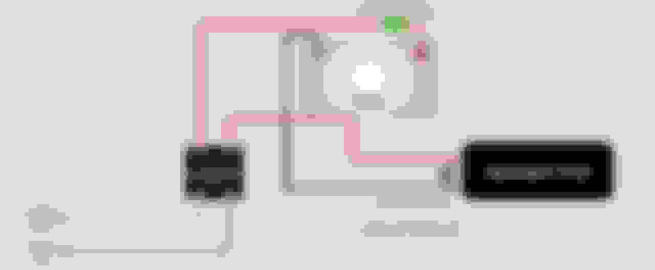
Looking to PWM my fuel pump (4301) so I don't have it cycling 100% at idle etc, but want to prove system out on cooling fans first cause losing a fan is not the end of the world. Is the below image I stole from the internet a valid approach? I have 40amp SSR DD and will be driving em via Holley -pwm
Looking to PWM my fuel pump (4301) so I don't have it cycling 100% at idle etc, but want to prove system out on cooling fans first cause losing a fan is not the end of the world. Is the below image I stole from the internet a valid approach? I have 40amp SSR DD and will be driving em via Holley -pwm
Seems too easy to be right, so has me worried.
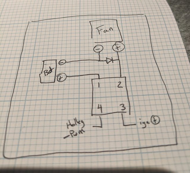
I'm no expert on SSRs, but I think your diagram shows the positive battery terminal going to the SSR terminal 1. Terminal 1 is the negative terminal.
Got new SSR's in today, and wired em how the schematic showed that came with em. Switching the negative side of the fan versus how I had em previously switching the hot side. Added in a fly back diode to both and so far so good.
If weather cooperates tmmr, I will drive it and see how they do.
Looking to PWM my fuel pump (4301) so I don't have it cycling 100% at idle etc, but want to prove system out on cooling fans first cause losing a fan is not the end of the world. Is the below image I stole from the internet a valid approach? I have 40amp SSR DD and will be driving em via Holley -pwm
Seems too easy to be right, so has me worried.
It is that easy, and the Crydom DC relay should be able to do 300Hz no problem at all. I run mine at 200Hz.
I tested at various frequencies and duties, and that just seemed to offer a little more flow than others.
Doesn't really matter which side you switch for the load. I switch the 12v side, simply as it's easier to ground the pumps locally and it means when off, there is no live going to the pumps at all.
I've a pair of 450's going, and intend to run a 3rd when needed. Currently on a 60A Crydom, but have a 100A if needed
Maybe pushing my luck, but I've never had to use the diode or flyback diode when using the standard FOTEK 100A SSR. Used it on alky pumps and fans. Never had an issue. What is the purpose of it? I mean I know what a diode does... just wasn't sure why it was needed. I'm pulsing the ground and not the power, but as mentioned don't know why it would matter.
Maybe pushing my luck, but I've never had to use the diode or flyback diode when using the standard FOTEK 100A SSR. Never had an issue. What is the purpose of it? I mean I know what a diode does... just wasn't sure why it was needed.
I am no EE, but I believe its to allow the energy remaining in motor coils a path to go instead of slamming back into the switch.
Ah, gotcha... Looking at the diagram I think they are built into the FOTEK SSR maybe? But the diodes look to be on the input not the output circuit? IDK what the coding means on some of the output circuit. Just thinking I might want to toss a diode on my alky pump when I install it in the new project this year, guess it can't hurt anyway!
Last edited by Forcefed86; Jan 4, 2021 at 07:54 AM.
Doesn't really matter which side you switch for the load. I switch the 12v side, simply as it's easier to ground the pumps locally and it means when off, there is no live going to the pumps at all.
I don't think it matters which side you switch from as long as you don't reverse the polarity to the ssr.
Originally Posted by Forcefed86
I know what a diode does... just wasn't sure why it was needed. I'm pulsing the ground and not the power, but as mentioned don't know why it would matter.
When the PWM goes to zero, the motor becomes a generator and the voltage it generates is opposite the voltage supplied. The solid state components in the ssr can't tolerate a big voltage in the reverse direction. This isn't as much of an issue with motors because the voltage they generate is fairly small. It's a big problem when driving heavy solenoids because their huge number of turns in the coils, generate a high reverse voltage that can wipe out the ssr components.
Originally Posted by Shownomercy
I am no EE, but I believe its to allow the energy remaining in motor coils a path to go instead of slamming back into the switch.
Yes, not so much slamming, but in reverse polarity.
Originally Posted by Forcefed86
Ah, gotcha... Looking at the diagram I think they are built into the FOTEK SSR maybe? BUt the diodes look to be on teh input not the output circuit? IDK what the coding means on some of the output circuit.
The diodes you see in that image are on the input side. They are the light Emitting Diodes (LED) that isolate the load from the input. There is no diode on the output side.
Maybe pushing my luck, but I've never had to use the diode or flyback diode when using the standard FOTEK 100A SSR. Used it on alky pumps and fans. Never had an issue. What is the purpose of it? I mean I know what a diode does... just wasn't sure why it was needed. I'm pulsing the ground and not the power, but as mentioned don't know why it would matter.
it's already been covered very well in other threads.
And a means of suppressing the back EMF IS essential unless all the components in the system have been designed to operate without it, which most SSR's are not.
Basically compare it to what happens in your ignition coil.
12v in....you switch it off and what happens in the windings ? The field collapse causes that build up of energy to release and because of the windings, it is a very very high voltage.
Any inductive load is basically the same, except when you PWM it, you're doing it hundreds, thousands of times per second.
Ah, gotcha... Looking at the diagram I think they are built into the FOTEK SSR maybe? But the diodes look to be on the input not the output circuit? IDK what the coding means on some of the output circuit. Just thinking I might want to toss a diode on my alky pump when I install it in the new project this year, guess it can't hurt anyway!
For my meth pump I just use the little Hella SSR, that's more or less a drop in replacement for a normal relay. It just needs some minor wiring change vs a normal relay, but means you can just plug it into the same relay holder so no ******* about with additional wiring, and it does have flyback protection built in. Although it only handles around 10-13A inductive loads from what I recall.
Still plenty for almost all methanol pumps except the most powerful, and even thing current will very much depend on how hard you're trying to work the pump.
Some drawings show a 1k resistor across the input side, this may be ecu dependent and may be a cause of yours staying on when you are "off".
ie. I believe this is for some ecu's or setups that behave strange, so that when you power off, both input terminals will be at the same potential...i.e off.
I have tried mine with the Syvecs with and without the resistor without issue, although I left the resistor in place. Because why not ?
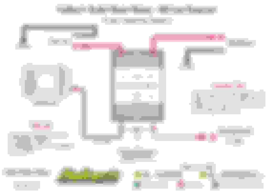
This is Haltech's drawing which is pretty clear, with the 12v side PWM'd ( obviously add fuses/protection where needed )
6 Common C5 Corvette Failures and What's Involved In Repairing Them
Slideshow: From wobbling harmonic balancers to failed EBCMs, these are the issues that define long-term C5 ownership and what repairs typically involve.
Retro Modern Bandit Pontiac Trans AM Comes With Burt Reynolds' Autograph
Slideshow: A modern Camaro transformed into a retro icon, this limited-run "Bandit" build blends nostalgia with brute force in a way few revivals manage.
Top 10 Greatest Cadillac V Series Performance Models Ever, Ranked
Slideshow: Cadillac didn't just crash the high-performance luxury vehicle party, it showed up loud, supercharged, and occasionally a little unhinged...
Coachbuilt N2A Anteros Is an LS2-Powered C6 Corvette In Italian Clothes
Slideshow: A one-off sports car that looks like a vintage Italian exotic-but hides a C6 Corvette underneath-just sold for the price of a new mid-engine Corvette.