
First turbo build, 70 GTO...
 12-20-2022 | 10:26 AM
#221

TECH Senior Member

Joined: Jul 2009
Posts: 7,927
Likes: 608
Great progress Andrew. If you get a chance to paint small pcs again, I highly recommend trying VHT Epoxy paint. They have two different can offerings. One is rollbar paint They come in satin and gloss. It�s much more durable IMO. It doesn�t need primer either. Just a thought
The following users liked this post:
Project GatTagO (12-20-2022)
12-20-2022 | 10:33 AM
#222
Thread Starter

Joined: Mar 2003
Posts: 10,244
Likes: 1,531
From: The City of Fountains
Great progress Andrew. If you get a chance to paint small pcs again, I highly recommend trying VHT Epoxy paint. They have two different can offerings. One is rollbar paint They come in satin and gloss. It�s much more durable IMO. It doesn�t need primer either. Just a thought
Andrew
 12-20-2022 | 01:07 PM
#224
After looking at it some more today, we are going to focus on the front entry HiRam lid. It only hits some bracing on the underside of the hood, and with that trimmed, the hood might actually close. I also spoke with my friend Jim at Holley. He designed many of the Holley intakes, including the HiRam. He said that cutting the throttle body flange off and trimming the front portion back would have a minimal impact on the air flow characteristics. So we may do that because that lessens the interference between the lid and the bracing on the bottom of the hood.
Andrew
Andrew
 12-20-2022 | 07:08 PM
#225
Thread Starter
Joined: Mar 2003
Posts: 10,244
Likes: 1,531
From: The City of Fountains
12-21-2022 | 10:16 PM
#226
Thread Starter
Joined: Mar 2003
Posts: 10,244
Likes: 1,531
From: The City of Fountains
Made a little progress today ahead of the blizzard that is going to hit tomorrow morning. Vic bead blasted the rotors to get the surface rust off and shot then with a coat of paint. I cleaned up the calipers and bolted everything together.
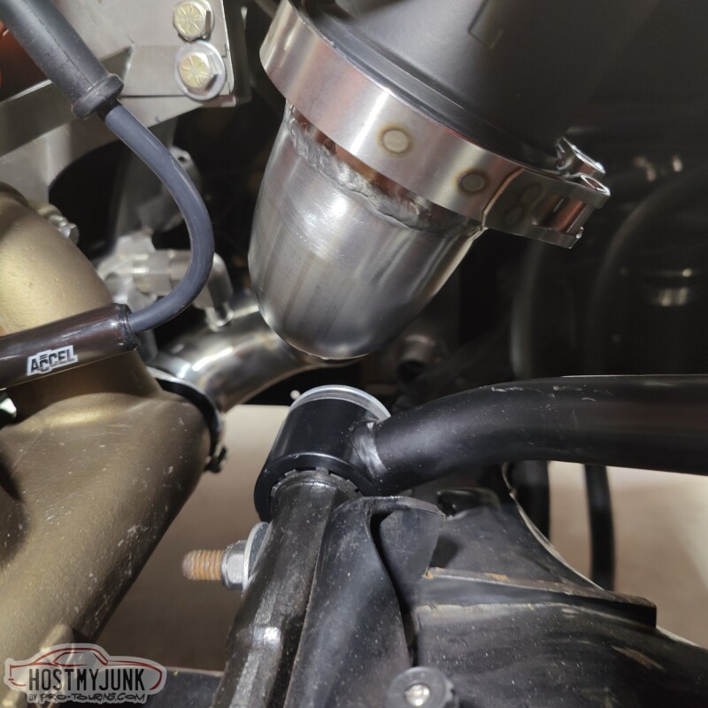
Some of you may notice that the caliper is on the back side of the rotors. These are brakes from a 98-2002 F-body and normally the caliper is on the front side of the rotor. The reason for the swap is that we messed up when we pressed the bearings on the axles. I accidentally installed the caliper brackets on the wrong sides. Instead of battling with pulling the bearings off and possibly damaging something, we decided to move the calipers to the rear. I swapped the calipers side to side so that the bleeder is at the top.
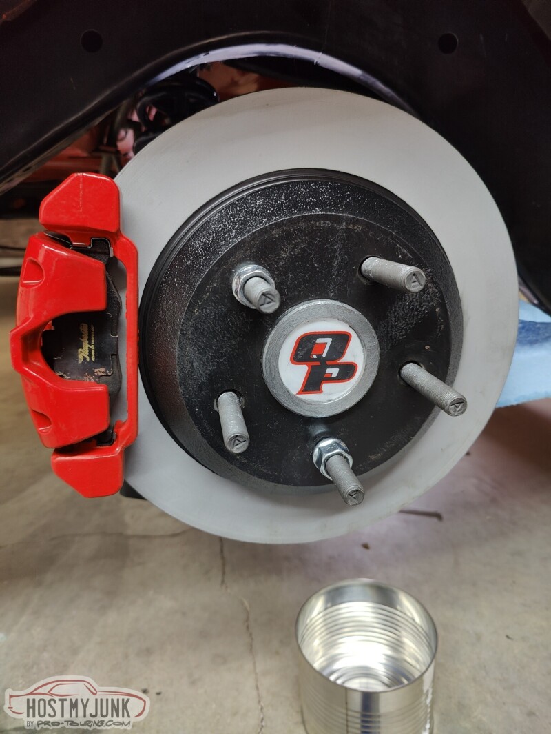
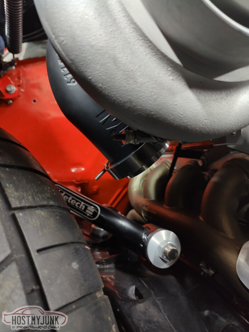
We put the car down on the ground in the front to check clearance with the suspension. The up-pipe is no pictured, but is about 1-1.5" away from the bushings. The Ridetech control arms use deleon bushings and I plan to wrap the up-pipe and also put a woven sock over it. I don't expect any issues.
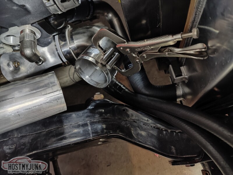
I got these nifty clamps from Australia, made by a company called SS Customs.
https://sscustoms.com.au
They have been super helpful holding the pipes together for mock-up and tack welding.
Andrew
Some of you may notice that the caliper is on the back side of the rotors. These are brakes from a 98-2002 F-body and normally the caliper is on the front side of the rotor. The reason for the swap is that we messed up when we pressed the bearings on the axles. I accidentally installed the caliper brackets on the wrong sides. Instead of battling with pulling the bearings off and possibly damaging something, we decided to move the calipers to the rear. I swapped the calipers side to side so that the bleeder is at the top.
We put the car down on the ground in the front to check clearance with the suspension. The up-pipe is no pictured, but is about 1-1.5" away from the bushings. The Ridetech control arms use deleon bushings and I plan to wrap the up-pipe and also put a woven sock over it. I don't expect any issues.
I got these nifty clamps from Australia, made by a company called SS Customs.
https://sscustoms.com.au
They have been super helpful holding the pipes together for mock-up and tack welding.
Andrew
12-22-2022 | 07:08 AM
#227
Who's disc brake kit is that, when I got my QP rear, I ordered one of their kits, used Ford Explorer brakes, mounted in the back like yours. They were a royal PITA, had this floating spacer for bearing preload, and zero room to navigate, lol.
I have seen those welding clamps, cool idea, nice to see firsthand experience with them.
I have seen those welding clamps, cool idea, nice to see firsthand experience with them.
The following users liked this post:
Project GatTagO (12-22-2022)
The following users liked this post:
Project GatTagO (12-22-2022)
12-22-2022 | 10:41 AM
#229
Thread Starter
Joined: Mar 2003
Posts: 10,244
Likes: 1,531
From: The City of Fountains
Who's disc brake kit is that, when I got my QP rear, I ordered one of their kits, used Ford Explorer brakes, mounted in the back like yours. They were a royal PITA, had this floating spacer for bearing preload, and zero room to navigate, lol.
I have seen those welding clamps, cool idea, nice to see firsthand experience with them.
I have seen those welding clamps, cool idea, nice to see firsthand experience with them.
Does anyone have any opinions as to where I should install the bung for the back pressure sensor?
Andrew
12-27-2022 | 10:25 PM
#230
Thread Starter
Joined: Mar 2003
Posts: 10,244
Likes: 1,531
From: The City of Fountains
With Christmas behind us, Vic and I are making slow, but steady progress.
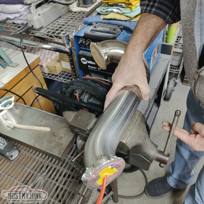
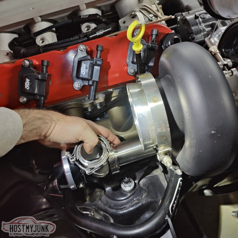
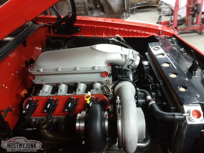
Today he was able to fully weld the up-pipe that goes between the Hooker exhaust manifold and the turbine inlet. He back-purged the pipe to avoid any "sugaring" on the inside.
Vic also welded a Summit branded clamp to the compressor discharge. It's one of those split clamps that has o-rings and allows for some movement as everything heats up. We also sorted out the filter situation, although I will be ordering a longer filter element to get as much surface area as possible. This one is 6.5" tall, and K&N has a 10" long version that will fit perfectly in the available space.
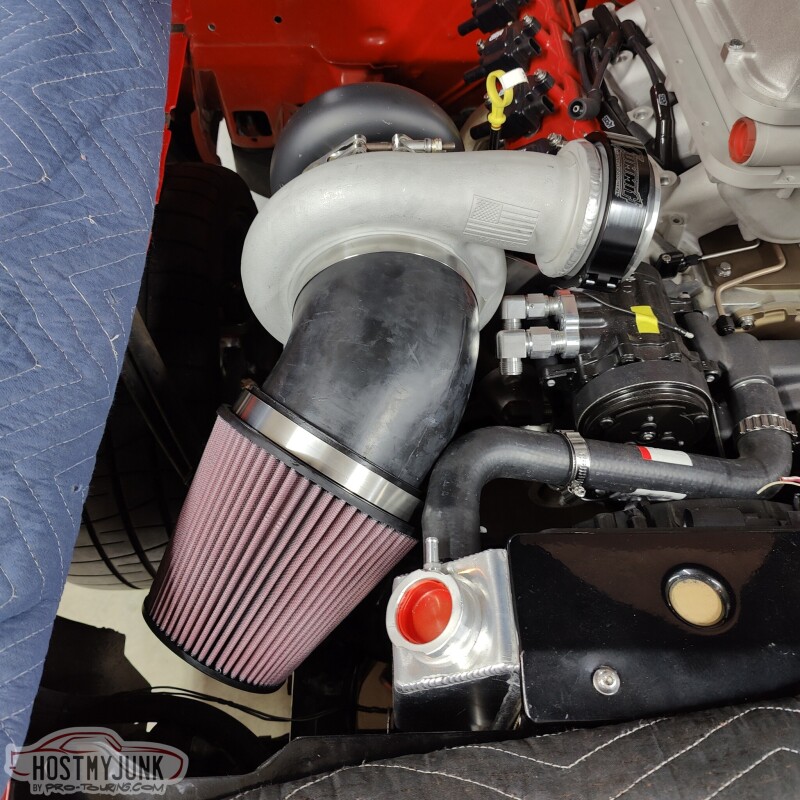
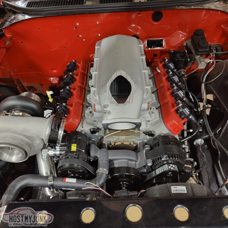
Now for the elephant in the room. The hood still doesn't close. This picture makes the situation look worse than it is, but you get the idea. The "bubble" at the top of the intake is about 1" too tall to allow the hood to close.
After considering all the options, we are going to start with the simple solution. We are going to mill down the bubble so the hood closes and see what we have left.
Andrew
Today he was able to fully weld the up-pipe that goes between the Hooker exhaust manifold and the turbine inlet. He back-purged the pipe to avoid any "sugaring" on the inside.
Vic also welded a Summit branded clamp to the compressor discharge. It's one of those split clamps that has o-rings and allows for some movement as everything heats up. We also sorted out the filter situation, although I will be ordering a longer filter element to get as much surface area as possible. This one is 6.5" tall, and K&N has a 10" long version that will fit perfectly in the available space.
Now for the elephant in the room. The hood still doesn't close. This picture makes the situation look worse than it is, but you get the idea. The "bubble" at the top of the intake is about 1" too tall to allow the hood to close.
After considering all the options, we are going to start with the simple solution. We are going to mill down the bubble so the hood closes and see what we have left.
Andrew
The following users liked this post:
C5_Pete (12-28-2022)
12-28-2022 | 06:51 AM
#231
What is that hose bet. the filter and comp. from, I think my comp. has a 5.5" flange, I need something to
try and get a filter on. I welded a 90 deg nipple on my top inlet, but it's still tight.
Did you decide to ditch the 90 deg intake for now?
try and get a filter on. I welded a 90 deg nipple on my top inlet, but it's still tight.
Did you decide to ditch the 90 deg intake for now?
12-28-2022 | 09:31 AM
#232
Thread Starter
Joined: Mar 2003
Posts: 10,244
Likes: 1,531
From: The City of Fountains
https://www.intakehoses.com/rubber-e...gree-1639.html
I'm not sure what you're asking in the second part.
Andrew
The following users liked this post:
n2xlr8n66 (12-28-2022)
12-28-2022 | 09:58 AM
#233

FWIW, after years of spending $$$$ for coatings, I started using KBS Extreme colatings on all my piping (cold, hot sides, exhaust). It's not nearly as cheap as wrap or sleeves, but the temperature drop is remarkable for a painted on product.
The following 3 users liked this post by n2xlr8n66:
12-28-2022 | 10:04 PM
#234
Thread Starter
Joined: Mar 2003
Posts: 10,244
Likes: 1,531
From: The City of Fountains
Back in 2010, I contacted The DriveShaft shop to solve a vibration issue in the GTO. They made me a CV driveshaft that use a CV at the slip yoke and a u-joint in the rear, which solved my vibration issues. Since then, many other A-body owners have done the same thing with the same, great results. When I built the Cougar, I wanted to go a step further and do a double CV shaft. That too had amazing results. If you look at any modern, RWD muscle car, that is exactly what you will see.
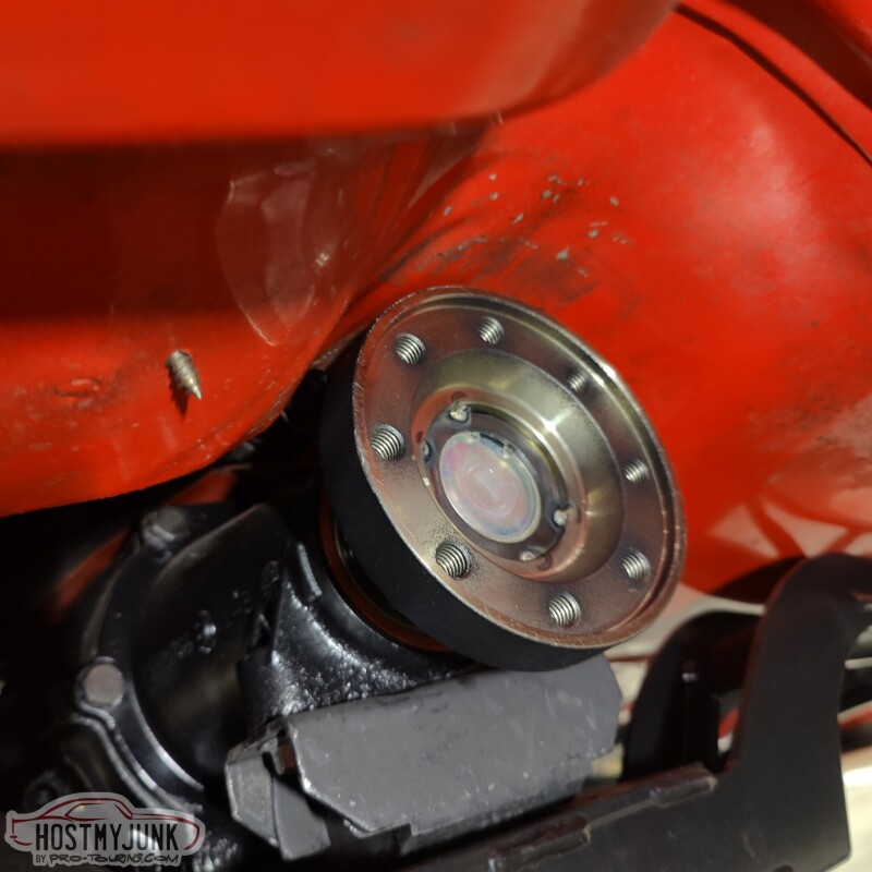
This version of the GTO will also get a dual CV driveshaft and this is the second part of that puzzle (the first being the CV pinion yoke). This slip yoke will use their new, non-plunging CV. This is the same CV they use on their high HP Nissan GTR and other driveshafts.
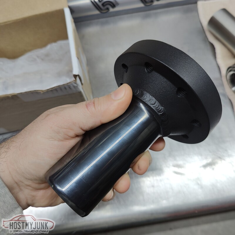
It's a tight fit, but there is a minimum of 3/8" all the way around the yoke. (what the hell was I thinking, twenty years ago, with the sheet metal screw?!)
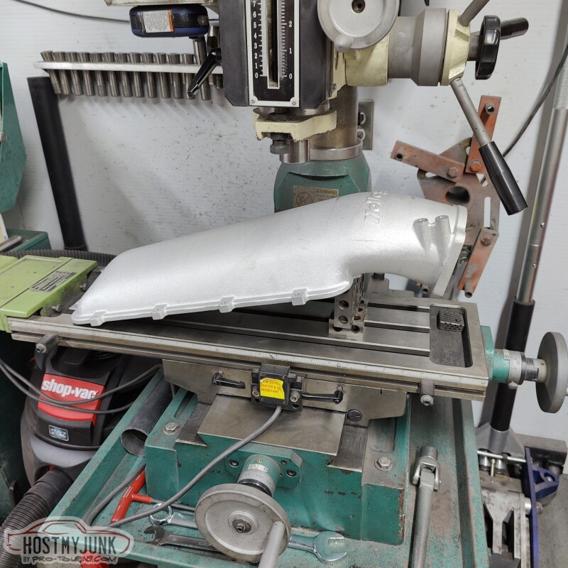
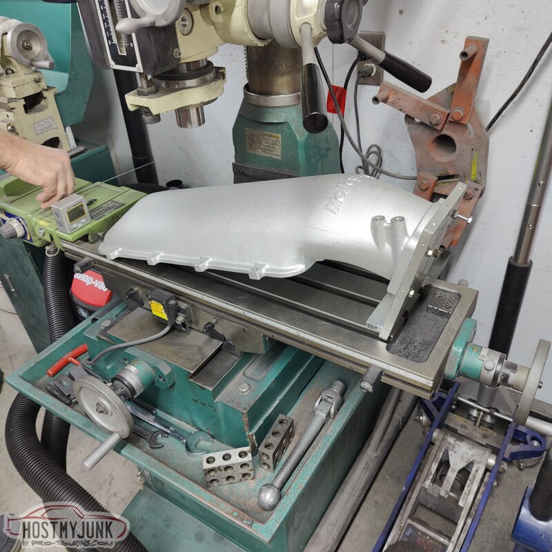
Vic made a fixture to hold the intake lid on the mill. We positioned it at the approximate angle of the hood.
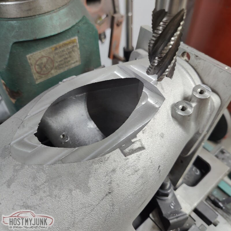
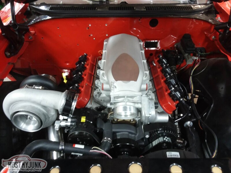
We took about 3/4" off the peak of the bubble and this was the hole that was made.
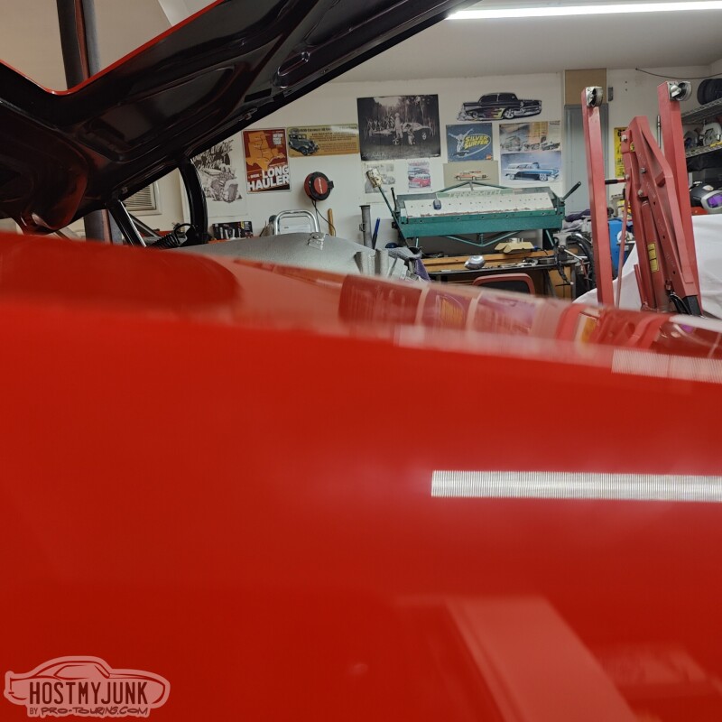
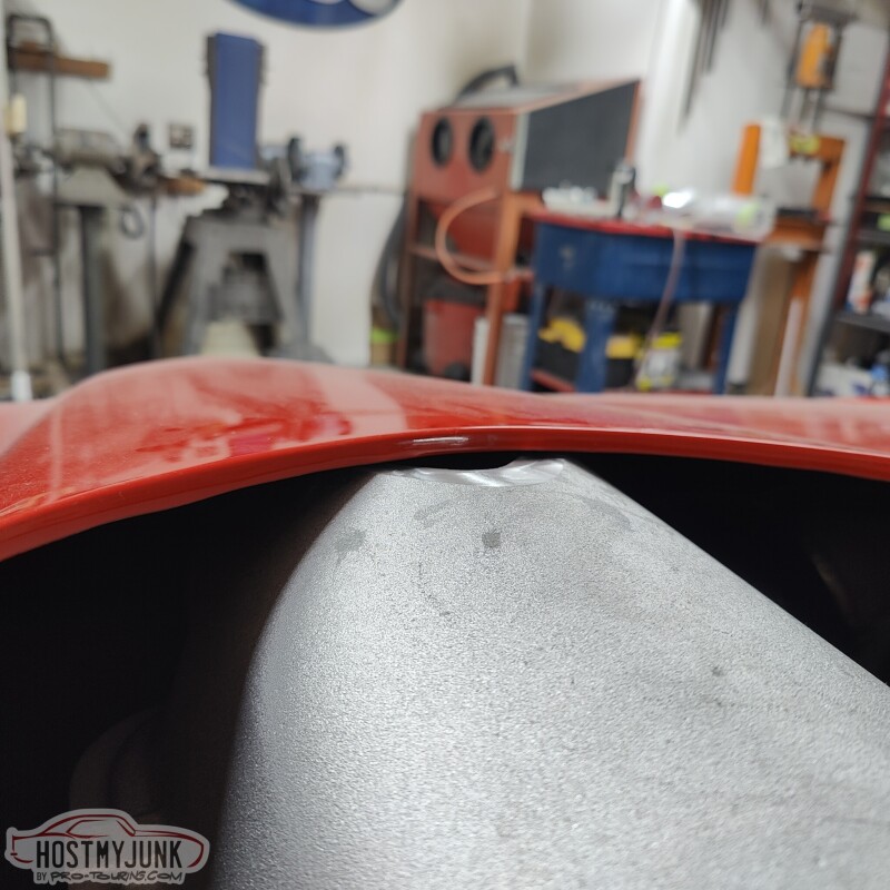
And the hood closed. As you can see, it is really tight, but nothing is touching. We are going to take a little bit more off to make room for the eventual plate that will get welded to cover the hole.
This is the current thinking on wastegate placement. My only reservation is that it be under the downpipe and will be a pain to get to if I have to do something with the wastegate.
The upside is that it will have excellent, priority flow and will merge back into the downpipe.
If anyone has thoughts on the wastegate placement, please chime in.
Andrew
This version of the GTO will also get a dual CV driveshaft and this is the second part of that puzzle (the first being the CV pinion yoke). This slip yoke will use their new, non-plunging CV. This is the same CV they use on their high HP Nissan GTR and other driveshafts.
It's a tight fit, but there is a minimum of 3/8" all the way around the yoke. (what the hell was I thinking, twenty years ago, with the sheet metal screw?!)
Vic made a fixture to hold the intake lid on the mill. We positioned it at the approximate angle of the hood.
We took about 3/4" off the peak of the bubble and this was the hole that was made.
And the hood closed. As you can see, it is really tight, but nothing is touching. We are going to take a little bit more off to make room for the eventual plate that will get welded to cover the hole.
This is the current thinking on wastegate placement. My only reservation is that it be under the downpipe and will be a pain to get to if I have to do something with the wastegate.
The upside is that it will have excellent, priority flow and will merge back into the downpipe.
If anyone has thoughts on the wastegate placement, please chime in.
Andrew
12-29-2022 | 08:03 AM
#236
Thread Starter
Joined: Mar 2003
Posts: 10,244
Likes: 1,531
From: The City of Fountains
12-29-2022 | 07:48 PM
#237

Do you think you'll have issues building boost with that big hole in the intake manifold?
Just kidding, progress looks great. I admire the effort to avoid cutting the hood.
For what it's worth I always routed my wastegate dump tubes into the downpipe to send the stinkies out the back.
Just kidding, progress looks great. I admire the effort to avoid cutting the hood.
For what it's worth I always routed my wastegate dump tubes into the downpipe to send the stinkies out the back.
12-29-2022 | 09:45 PM
#239
Thread Starter
Joined: Mar 2003
Posts: 10,244
Likes: 1,531
From: The City of Fountains

This morning I spent a few hours trying to help a local customer with a Coyote no-start issue, so I didn't have time mess with the car. But Vic sent me these pictures in the afternoon.
I think as far as looks go, it looks pretty good.
Tomorrow I will have a chance to go se it in person and see what kind of clearance there is with the hood. We are also going to install the Ring Brothers billet hinges, just to make sure everything fits the way it should.
Andrew
The following users liked this post:
Pro Stock John (12-30-2022)
12-30-2022 | 07:21 AM
#240
