
First turbo build, 70 GTO...

The following users liked this post:
Project GatTagO (02-20-2023)
 02-20-2023 | 01:50 PM
#302
Thread Starter
Joined: Mar 2003
Posts: 10,244
Likes: 1,533
From: The City of Fountains
The following 2 users liked this post by Project GatTagO:
C5_Pete (02-23-2023), Pro Stock John (02-20-2023)
02-21-2023 | 10:42 PM
#303
Thread Starter
Joined: Mar 2003
Posts: 10,244
Likes: 1,533
From: The City of Fountains
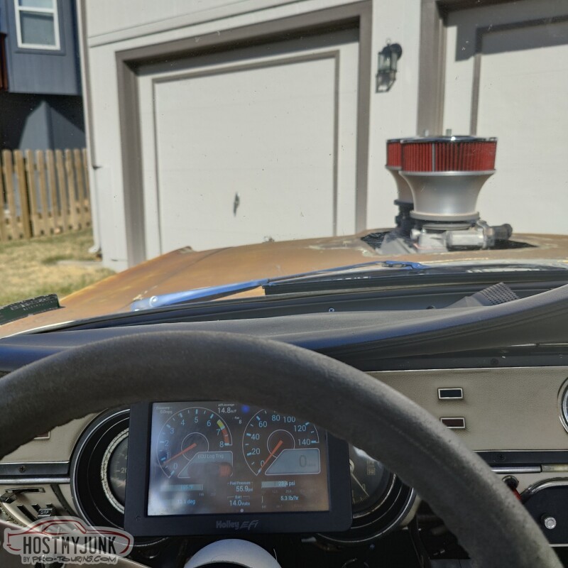
Today it was "drive your hotrod to work day" so I drove the Cougar to Vic's place.
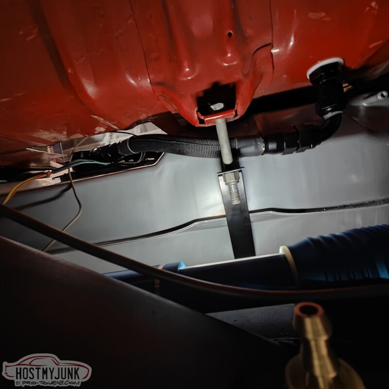
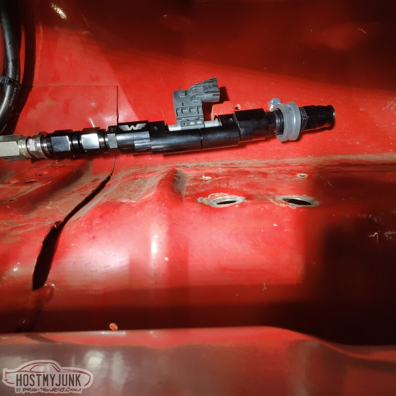
I put some fabric sleeving on the fuel line that goes from the pump to the bulkhead. This is how it looks when viewed from the bottom. It looks like it is touching, but there is clearance all around that hose.
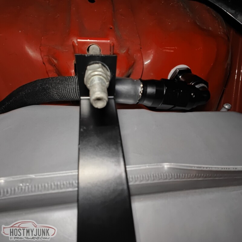
This view is from the front, looking over the top of the rear axle.
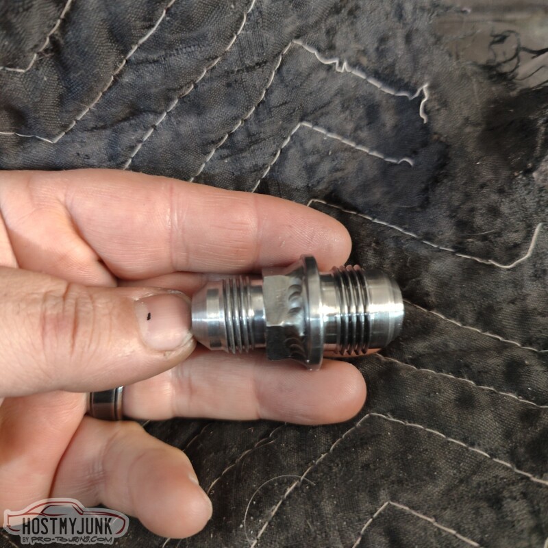
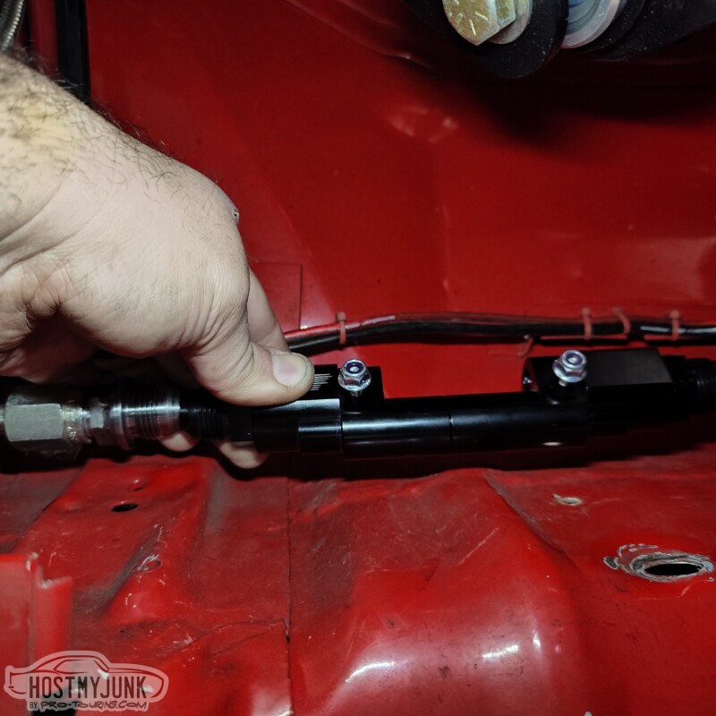
Once that was sorted, I moved to the other side where the 1/2" stainless tube terminates. The top fitting is what I had in there. It is a -AN8 to -AN6 male union.
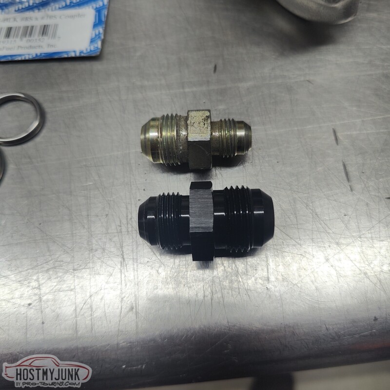
Since the fuel like that I am using in the rear is -AN10, I needed the adapter shown at the bottom. The one that I got from Star Performance was aluminum, as they didn't have any steel ones. After discussing it with Vic, it was decided that a steel fitting would be more appropriate. So we got a -AN10, steel male weld bung, and Vic made a new fitting, using part of the old fitting.
The other thing that I decided to change was not have the flex fuel sensor holder be right after the fuel filter. Even with the filter shifted to the left as much as possible, I just don't have the linear room to mount everything and still have enough room for the hoses to routed appropriately. With the flex fuel holder gone, this is how I plan to run the hose. It will sweep gently, back under the trunk floor and turn back towards the right side, where the stainless tube is located.
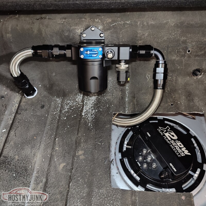
The flex fuel sensor holder will be attached to the end of the tube with a -AN10 to -AN10 female union.
Andrew
I put some fabric sleeving on the fuel line that goes from the pump to the bulkhead. This is how it looks when viewed from the bottom. It looks like it is touching, but there is clearance all around that hose.
This view is from the front, looking over the top of the rear axle.
Once that was sorted, I moved to the other side where the 1/2" stainless tube terminates. The top fitting is what I had in there. It is a -AN8 to -AN6 male union.
Since the fuel like that I am using in the rear is -AN10, I needed the adapter shown at the bottom. The one that I got from Star Performance was aluminum, as they didn't have any steel ones. After discussing it with Vic, it was decided that a steel fitting would be more appropriate. So we got a -AN10, steel male weld bung, and Vic made a new fitting, using part of the old fitting.
The other thing that I decided to change was not have the flex fuel sensor holder be right after the fuel filter. Even with the filter shifted to the left as much as possible, I just don't have the linear room to mount everything and still have enough room for the hoses to routed appropriately. With the flex fuel holder gone, this is how I plan to run the hose. It will sweep gently, back under the trunk floor and turn back towards the right side, where the stainless tube is located.
The flex fuel sensor holder will be attached to the end of the tube with a -AN10 to -AN10 female union.
Andrew
The following users liked this post:
C5_Pete (02-23-2023)
02-24-2023 | 10:54 AM
#304

I know this is a little delayed, but it would be easy to make some out of exhaust pipe and 3/8" or 1/4" dowel. And for thinner ones, t bolt clamps. Thats my plan anyways.
The following 2 users liked this post by Kfxguy:
C5_Pete (02-26-2023), Project GatTagO (02-25-2023)
02-26-2023 | 10:59 AM
#305
Thread Starter
Joined: Mar 2003
Posts: 10,244
Likes: 1,533
From: The City of Fountains
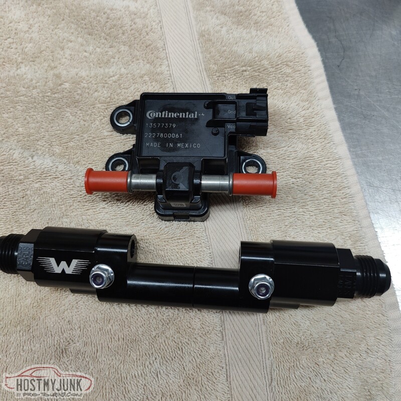
I got the flex fuel sensor, but of course I got the wrong one to work with the Motion Raceworks holder...
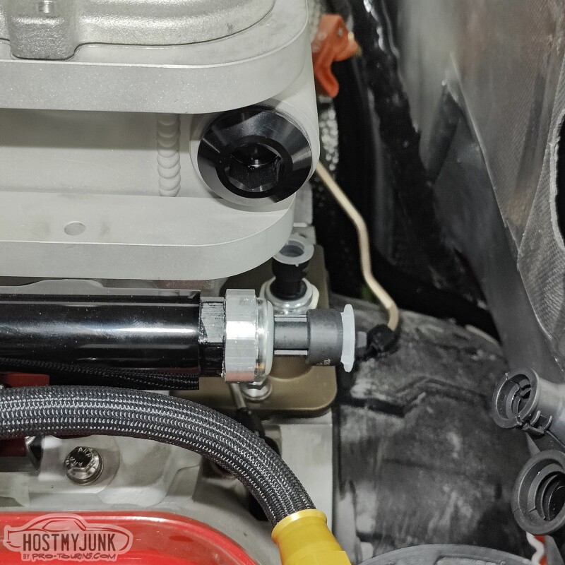
I was missing one last fitting to complete the intercooler hoses. The inlet to the intercooler needs a 45 degree fitting in order to clear the fuel rail that is below it. I used the fabric heat shrink on top of the Earl's Super Stock hose and it looks remarkably similar to the Earl's Ultra Pro hose.
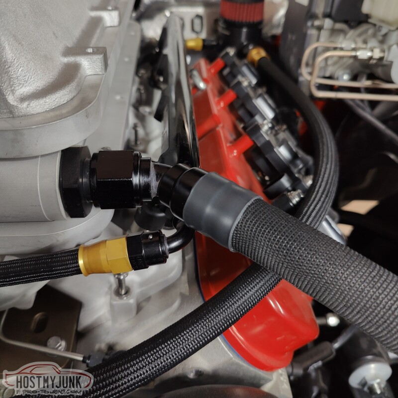
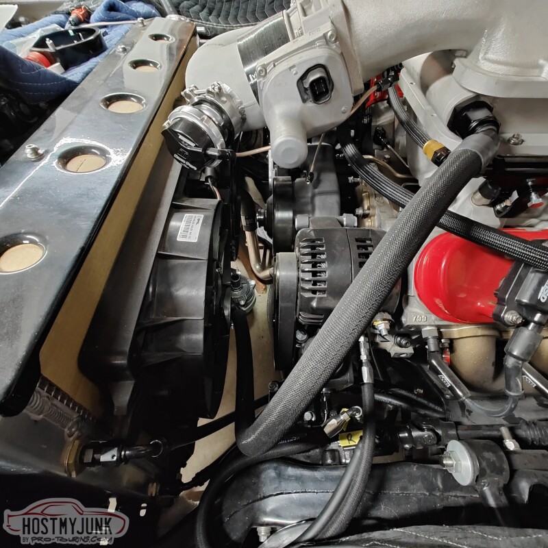
This hose makes a gentle sweep down and towards the center of the fan shroud...
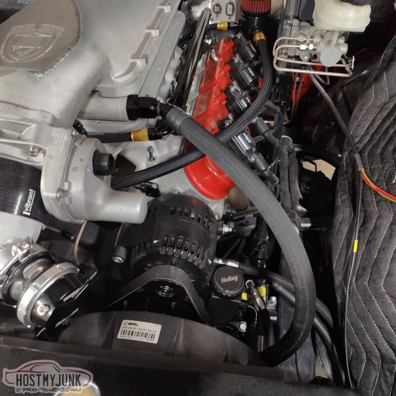
Where it connects to the water pump. You can see the pump mounted to the fan shroud.
Vic took a couple of fittings and welded them together to make an adapter.
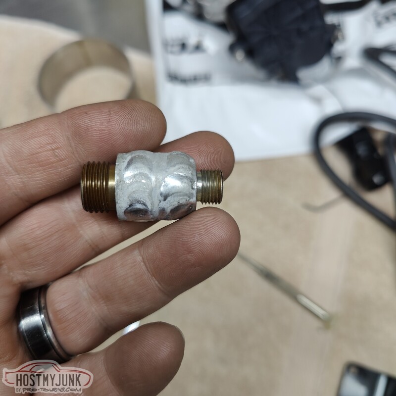
The adapter is used to mount the pressure relief valve.
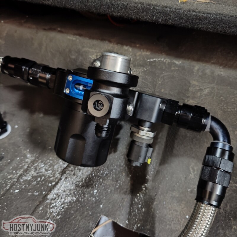
Carl from VaporWorx told me this was necessary to keep the system from getting vapor locked. He told me to purchase a small Radium Engineering fuel pressure regulator and send me a special 80psi diaphragm for it.
When the car has been running for a while, then it is turned off, pressure in the feed line can build up and lock up the injectors from firing. This valve will burn the feed line once the pressure exceeds 80psi.
I also got a modern Helical exhaust valve that uses a K�ster 3 pin motor. This will be controlled by the Holley Dominator ECU.
Andrew
I was missing one last fitting to complete the intercooler hoses. The inlet to the intercooler needs a 45 degree fitting in order to clear the fuel rail that is below it. I used the fabric heat shrink on top of the Earl's Super Stock hose and it looks remarkably similar to the Earl's Ultra Pro hose.
This hose makes a gentle sweep down and towards the center of the fan shroud...
Where it connects to the water pump. You can see the pump mounted to the fan shroud.
Vic took a couple of fittings and welded them together to make an adapter.
The adapter is used to mount the pressure relief valve.
Carl from VaporWorx told me this was necessary to keep the system from getting vapor locked. He told me to purchase a small Radium Engineering fuel pressure regulator and send me a special 80psi diaphragm for it.
When the car has been running for a while, then it is turned off, pressure in the feed line can build up and lock up the injectors from firing. This valve will burn the feed line once the pressure exceeds 80psi.
I also got a modern Helical exhaust valve that uses a K�ster 3 pin motor. This will be controlled by the Holley Dominator ECU.
Andrew
The following 2 users liked this post by Project GatTagO:
C5_Pete (02-27-2023), Pro Stock John (02-26-2023)
02-28-2023 | 09:39 PM
#306
Thread Starter
Joined: Mar 2003
Posts: 10,244
Likes: 1,533
From: The City of Fountains
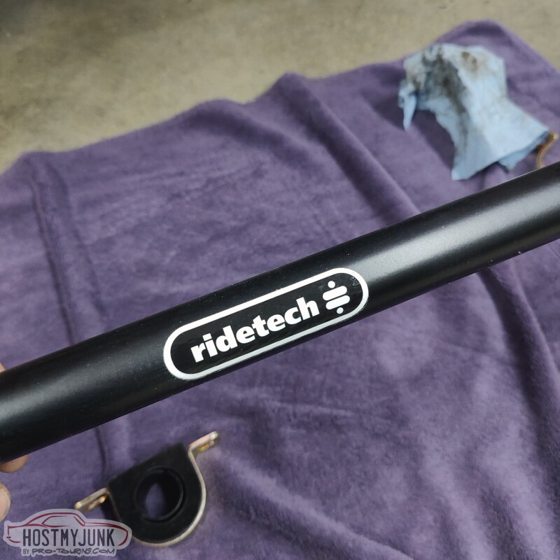
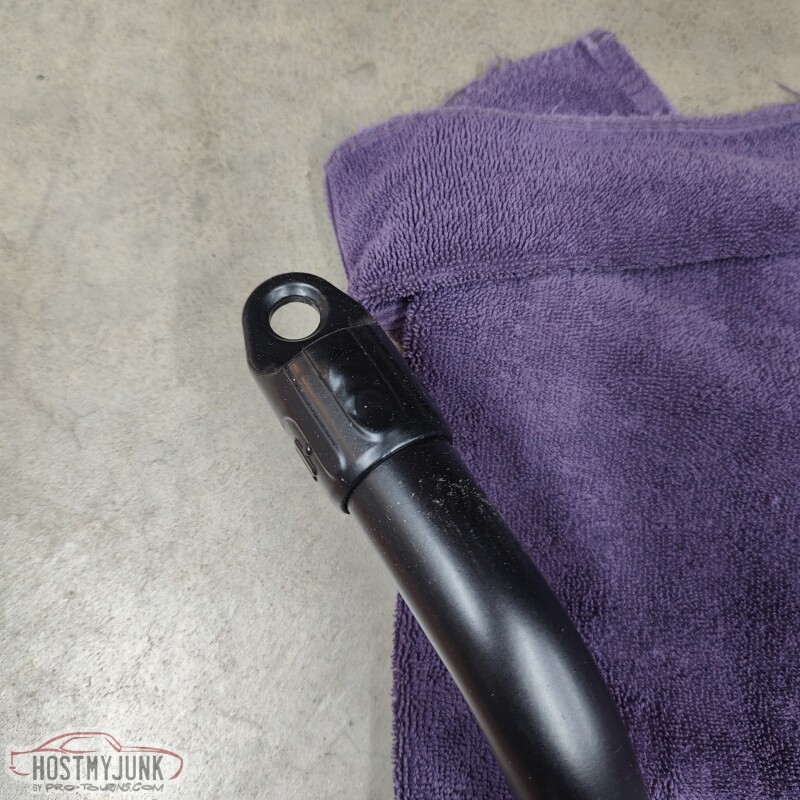
Today I decided to leave the plumbing for a while and tackle one of the last big boxes that I have. As mentioned before, this car now has a complete Ridetech suspension, front and rear, and part of that package are front and rear sway bars. This is the front sway bar.
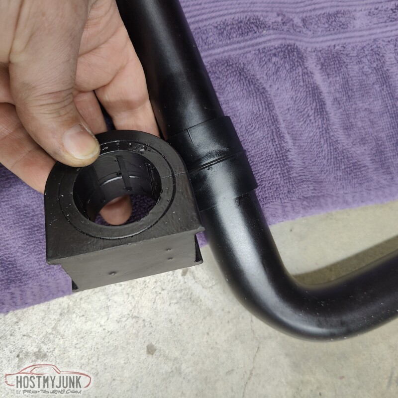
This sway bar kit is very thought out. The bushings are polyurethane, but they also include this slick Delrin bushing, which is supposed to eliminate the need for lube and is supposed to eliminate squeaks, which are so common with polyurethane bushings.
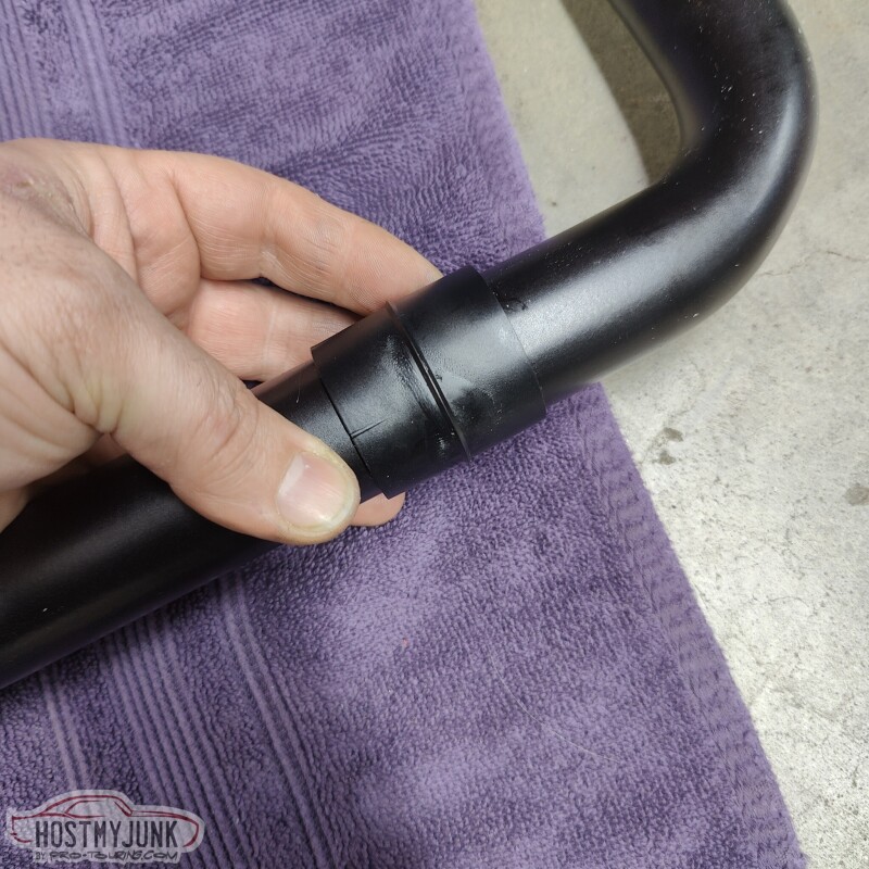
The ridge on the Delrin bushing rides inside a groove in the middle of the bushing, which keeps the bushing from sliding out.
Judging by the weight, the bar is hollow and has there bushing ends welded to both sides.
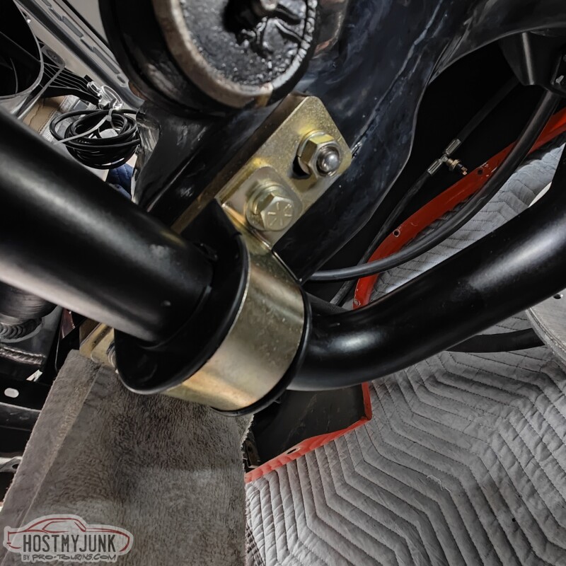
The mounting system includes some plates that move the bar about 1" forward. This is done to clear the pitman arm on the passenger side. My old swaybar used to rub a little bit against the edge of the pitman arm. You can see that now there is a solid inch of clearance.
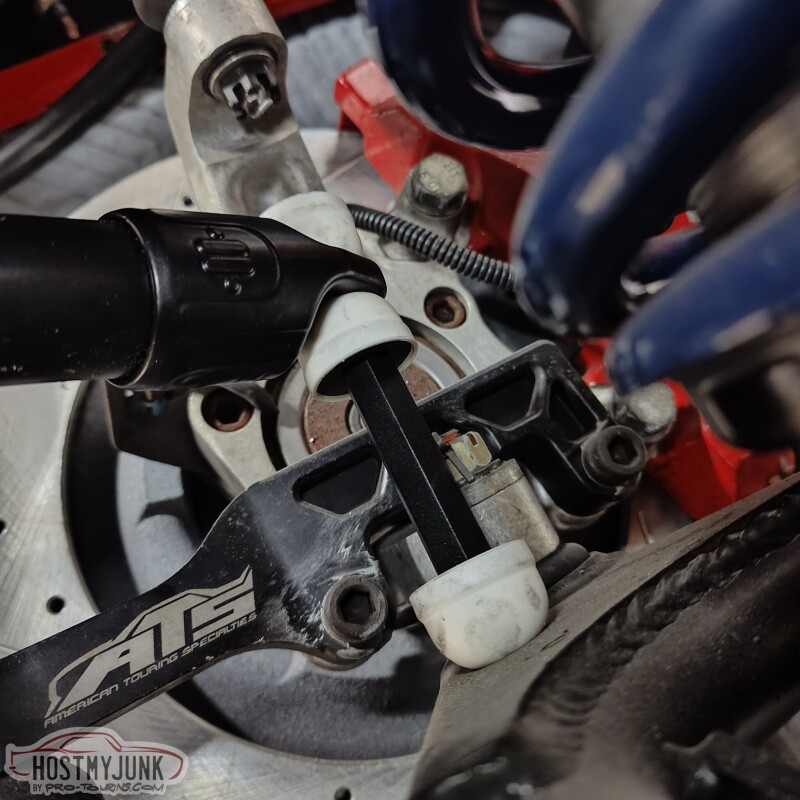
The end links are Moog parts and also did not call for any lube.
Lastly, I also dug out the mating connectors for the bulkhead panel.
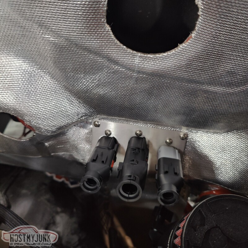
The connectors have the optional "backs" on them, so that I can fully cover the wires. The "backs" also provide added strain relief, which is very important for all connectors.
Andrew
This sway bar kit is very thought out. The bushings are polyurethane, but they also include this slick Delrin bushing, which is supposed to eliminate the need for lube and is supposed to eliminate squeaks, which are so common with polyurethane bushings.
The ridge on the Delrin bushing rides inside a groove in the middle of the bushing, which keeps the bushing from sliding out.
Judging by the weight, the bar is hollow and has there bushing ends welded to both sides.
The mounting system includes some plates that move the bar about 1" forward. This is done to clear the pitman arm on the passenger side. My old swaybar used to rub a little bit against the edge of the pitman arm. You can see that now there is a solid inch of clearance.
The end links are Moog parts and also did not call for any lube.
Lastly, I also dug out the mating connectors for the bulkhead panel.
The connectors have the optional "backs" on them, so that I can fully cover the wires. The "backs" also provide added strain relief, which is very important for all connectors.
Andrew
Last edited by Project GatTagO; 03-03-2023 at 09:20 PM.
The following users liked this post:
C5_Pete (03-01-2023)
03-07-2023 | 06:47 PM
#307
Thread Starter
Joined: Mar 2003
Posts: 10,244
Likes: 1,533
From: The City of Fountains
With spring quickly coming, my tuning business has been picking up steam, which means less time to work on the GTO, but I managed to knock out a couple of tasks.
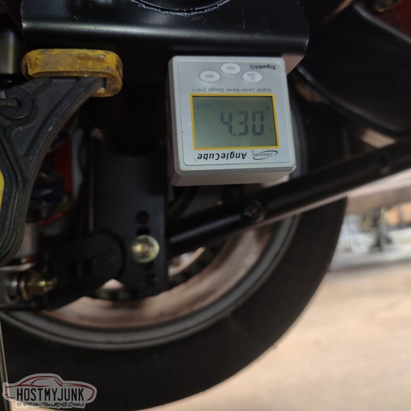
First up is the Ridetech rear sway bar. The kit comes with these brackets that would normally be held in place by a U-bolt. This this rear housing has a back brace, the bracket no longer fits around the axle tube. I trimmed the parts that were interfering and used an angle finder to make sure that both brackets were at the same angle. The actual angle is not critical, but having them be the same seemed pretty important.
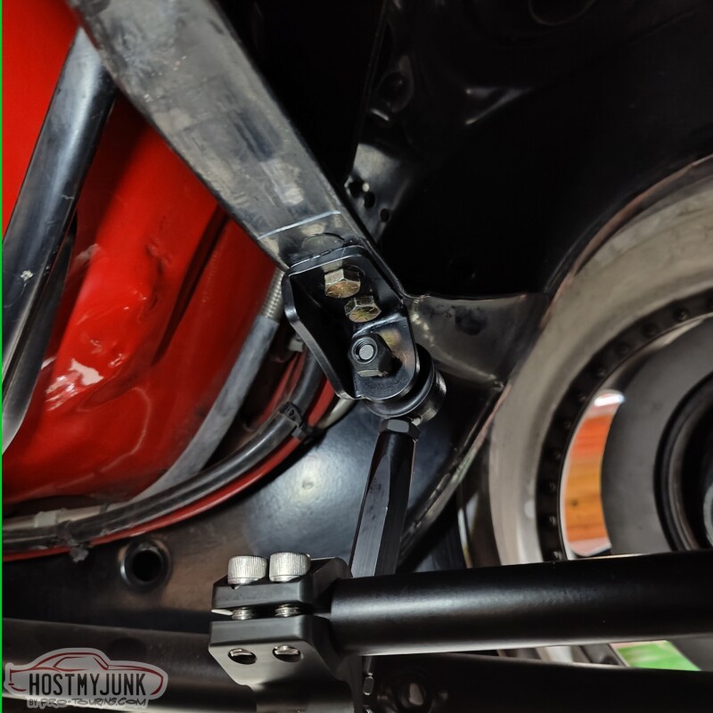
Next, I drilled some holes in the frame for the end link brackets. This is the driver's wide.
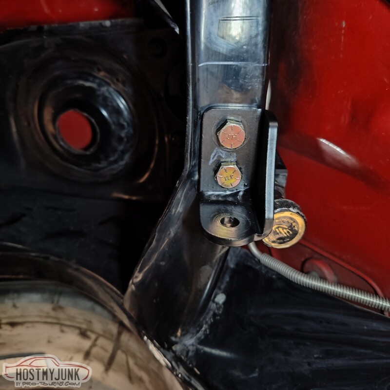
This is the passenger side with the sway bar bracket and the end link installed.
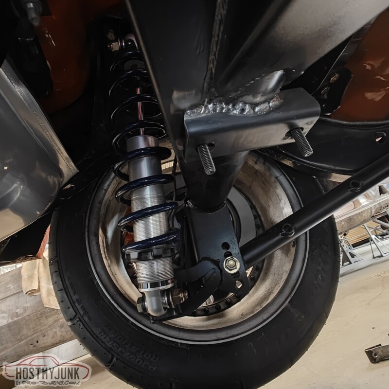
Vic got a new MIG welded and I buggered it in place. The welds are not pretty, but they will be fine.
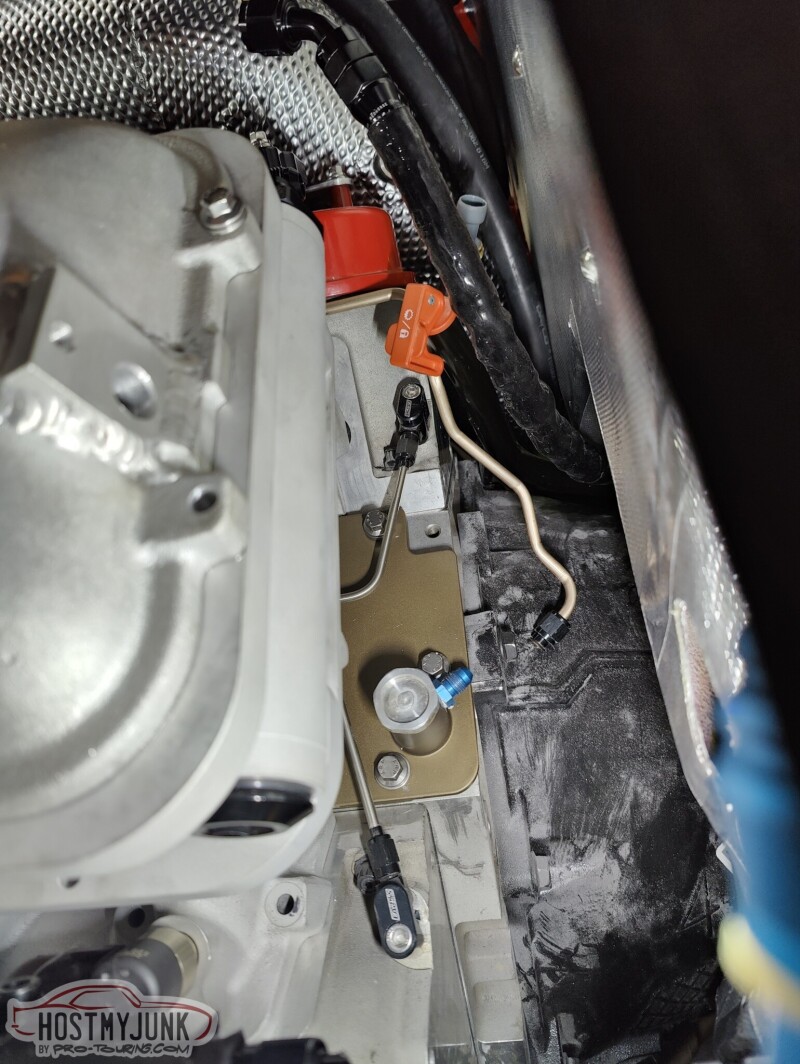
Lastly, fiddled around with the flex fuel sensor holder. I didn't want the sensor to just be hanging by the AN union without any support. I used a large P clamp to support the other side where the fuel line will attach.
Andrew
First up is the Ridetech rear sway bar. The kit comes with these brackets that would normally be held in place by a U-bolt. This this rear housing has a back brace, the bracket no longer fits around the axle tube. I trimmed the parts that were interfering and used an angle finder to make sure that both brackets were at the same angle. The actual angle is not critical, but having them be the same seemed pretty important.
Next, I drilled some holes in the frame for the end link brackets. This is the driver's wide.
This is the passenger side with the sway bar bracket and the end link installed.
Vic got a new MIG welded and I buggered it in place. The welds are not pretty, but they will be fine.
Lastly, fiddled around with the flex fuel sensor holder. I didn't want the sensor to just be hanging by the AN union without any support. I used a large P clamp to support the other side where the fuel line will attach.
Andrew
03-09-2023 | 09:35 PM
#308
Thread Starter
Joined: Mar 2003
Posts: 10,244
Likes: 1,533
From: The City of Fountains
I take inspiration from all kinds of places. A while back I ran across a build on the Rad Rides website. It was the 1961 Brookwood wagon built for George Poteet:
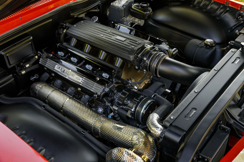
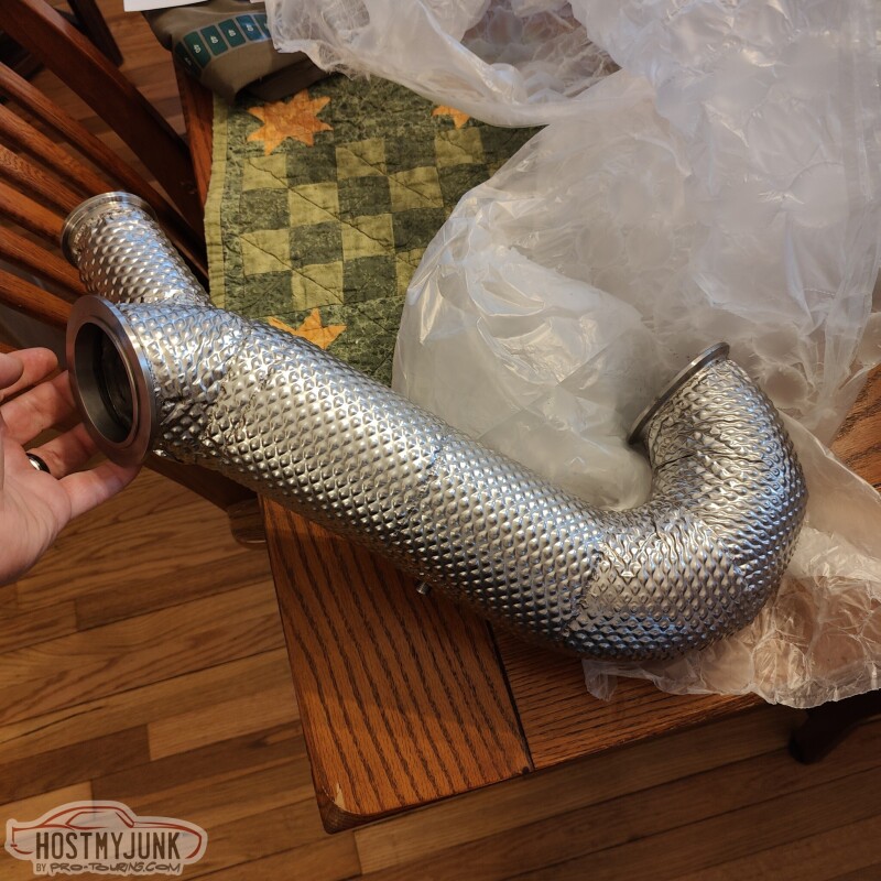
When I was at PRI I went to the booth of the vendor that did the cladding on the downpipe. The company is HeaderShield. I emailed them after the show, sent pictures of my parts, they gave me a quote, I paid it, sent my parts in, and ten weeks later I got them back.
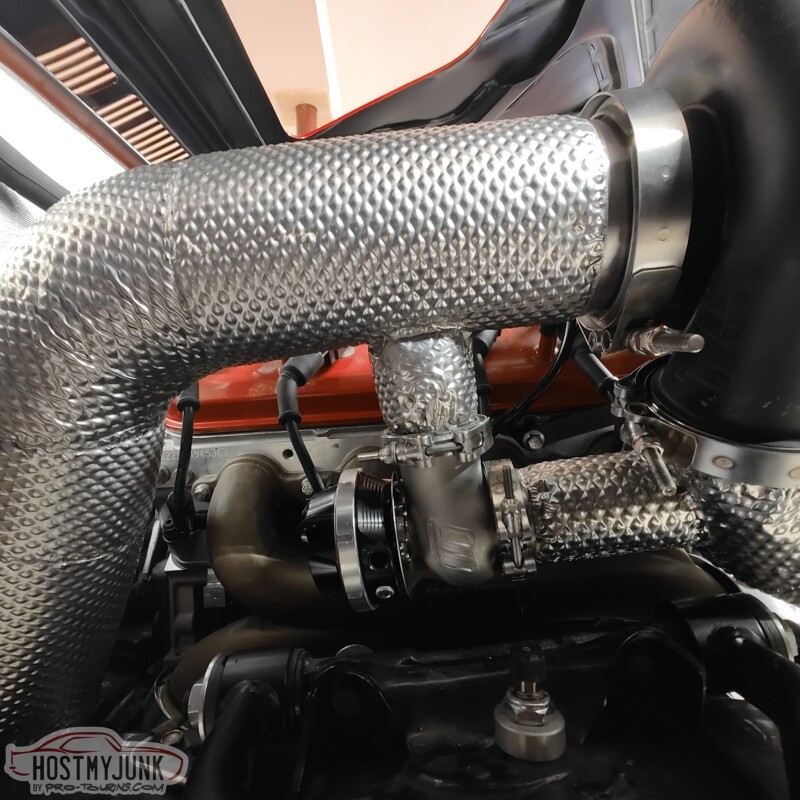
This is the up-pipe that goes from the Holley manifold exit to the turbine inlet.
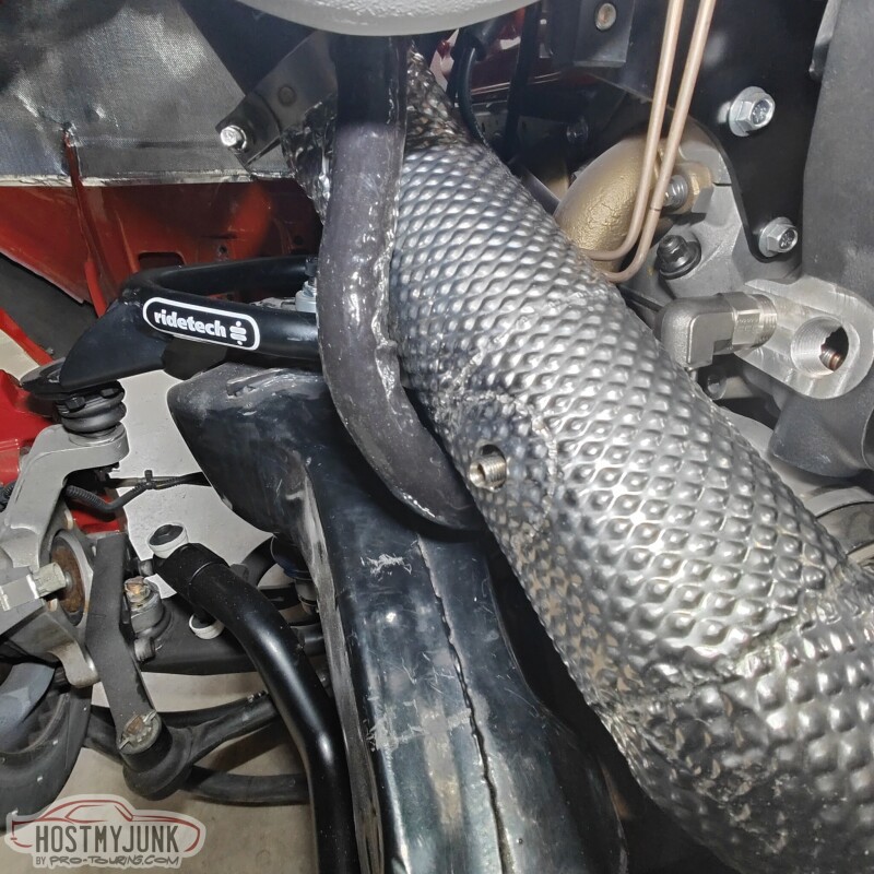
This is the downpipe that feeds the exhaust from the turbine, under the car.
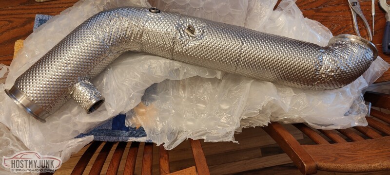
The rest of the exhaust will take off from the downpipe.
Andrew
When I was at PRI I went to the booth of the vendor that did the cladding on the downpipe. The company is HeaderShield. I emailed them after the show, sent pictures of my parts, they gave me a quote, I paid it, sent my parts in, and ten weeks later I got them back.
This is the up-pipe that goes from the Holley manifold exit to the turbine inlet.
This is the downpipe that feeds the exhaust from the turbine, under the car.
The rest of the exhaust will take off from the downpipe.
Andrew

The following users liked this post:
Project GatTagO (03-10-2023)
03-10-2023 | 09:22 AM
#311
Thread Starter
Joined: Mar 2003
Posts: 10,244
Likes: 1,533
From: The City of Fountains
03-10-2023 | 09:34 PM
#312
Thread Starter
Joined: Mar 2003
Posts: 10,244
Likes: 1,533
From: The City of Fountains
I brought the pipes over to Vic's and installed them, hopefully for good. The downpipe fits great, although it is about 1/8 inch away from the frame. I am hoping the cladding will keep the powder coating on the frame from burning off.
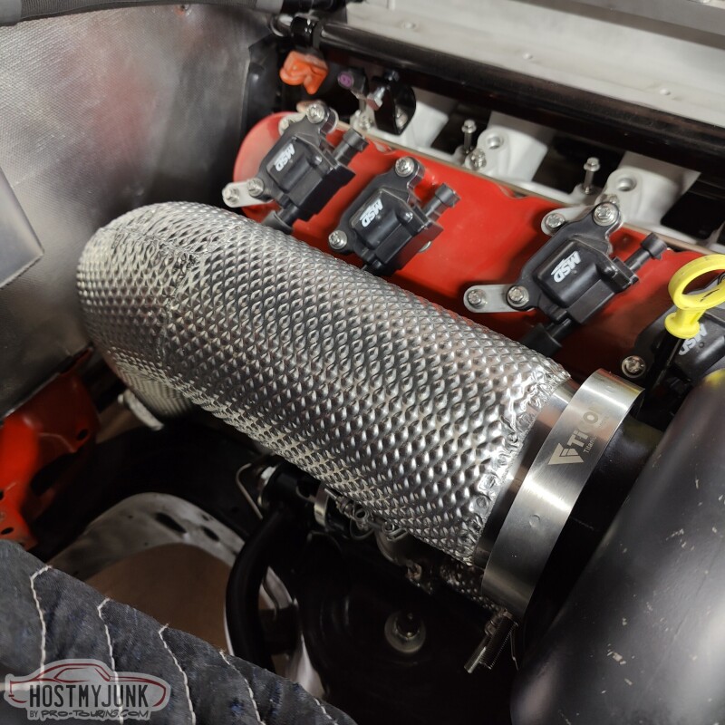
Here is the up-pipe, going from the Hooker exhaust manifold to the turbine inlet. If you look closely, you can see the bung for the EGT probe.
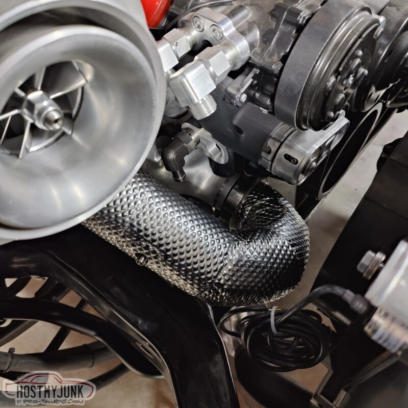
Here is the wastegate plumbing. The wastegate itself will get a little blanket, as will the turbine housing. Both from Funk Motorsports in England.
Here you can see the oil drain. Remember, it is stainless steel, but I also added an insulating sleeve over the top. The EGT bung is also clearly visible.
This is just an overall shot of how things are looking.
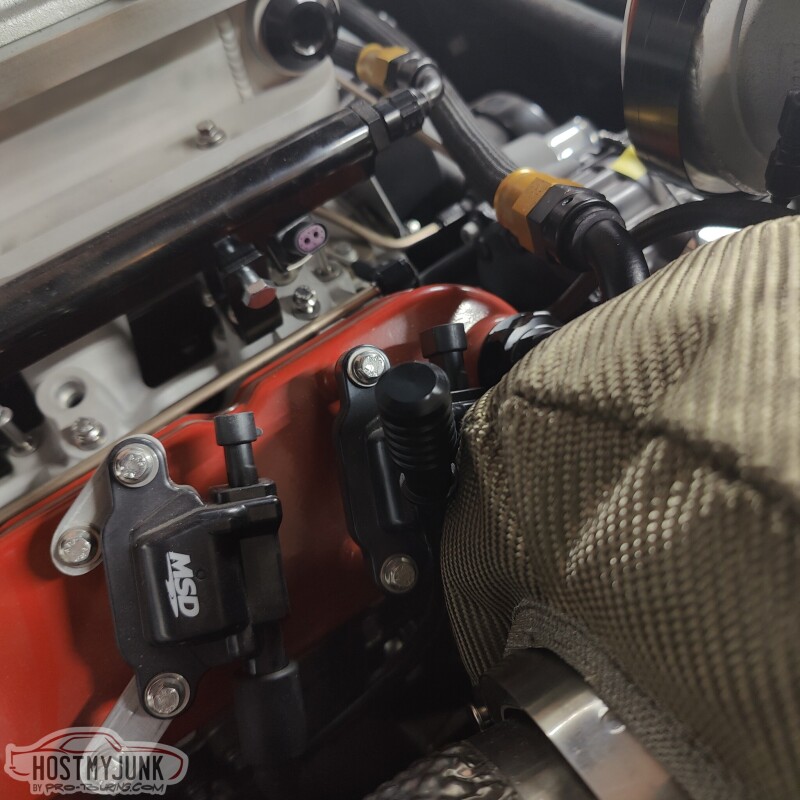
The yellow dipstick handle needs to go...
Andrew
Here is the up-pipe, going from the Hooker exhaust manifold to the turbine inlet. If you look closely, you can see the bung for the EGT probe.
Here is the wastegate plumbing. The wastegate itself will get a little blanket, as will the turbine housing. Both from Funk Motorsports in England.
Here you can see the oil drain. Remember, it is stainless steel, but I also added an insulating sleeve over the top. The EGT bung is also clearly visible.
This is just an overall shot of how things are looking.
The yellow dipstick handle needs to go...
Andrew
The following 2 users liked this post by Project GatTagO:
C5_Pete (03-11-2023), The BallSS (03-15-2023)
03-10-2023 | 09:55 PM
#313

Love the exhaust cladding- very nice.
Not sure I'd wrap the WG. I'd want it to shed as much heat as possible, and it looks like you have the required clearnace to work just fine.
Top notch work, Andrew.
Not sure I'd wrap the WG. I'd want it to shed as much heat as possible, and it looks like you have the required clearnace to work just fine.
Top notch work, Andrew.
The following users liked this post:
Project GatTagO (03-12-2023)
03-14-2023 | 09:11 PM
#314
Thread Starter
Joined: Mar 2003
Posts: 10,244
Likes: 1,533
From: The City of Fountains
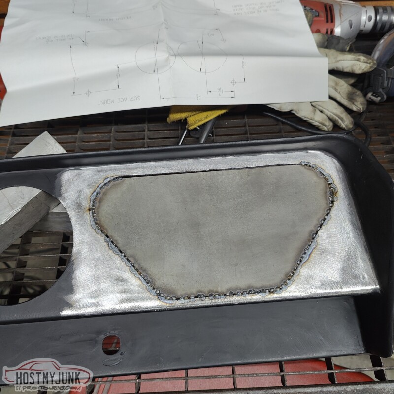
The whole area behind the rear seat was covered with MLV. It was sad to have to cut into it...
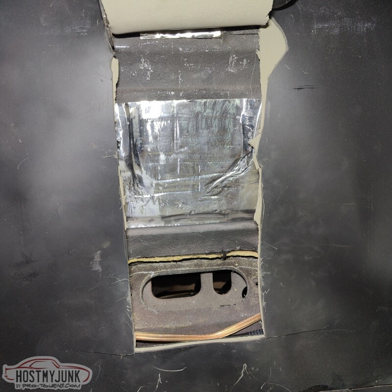
But I needed access so that I could install this...
It is a OEM fuel vapor separator. I plan to vent the tank though this and then into a small charcoal canister. That should keep most of the fuel vapors at bay.
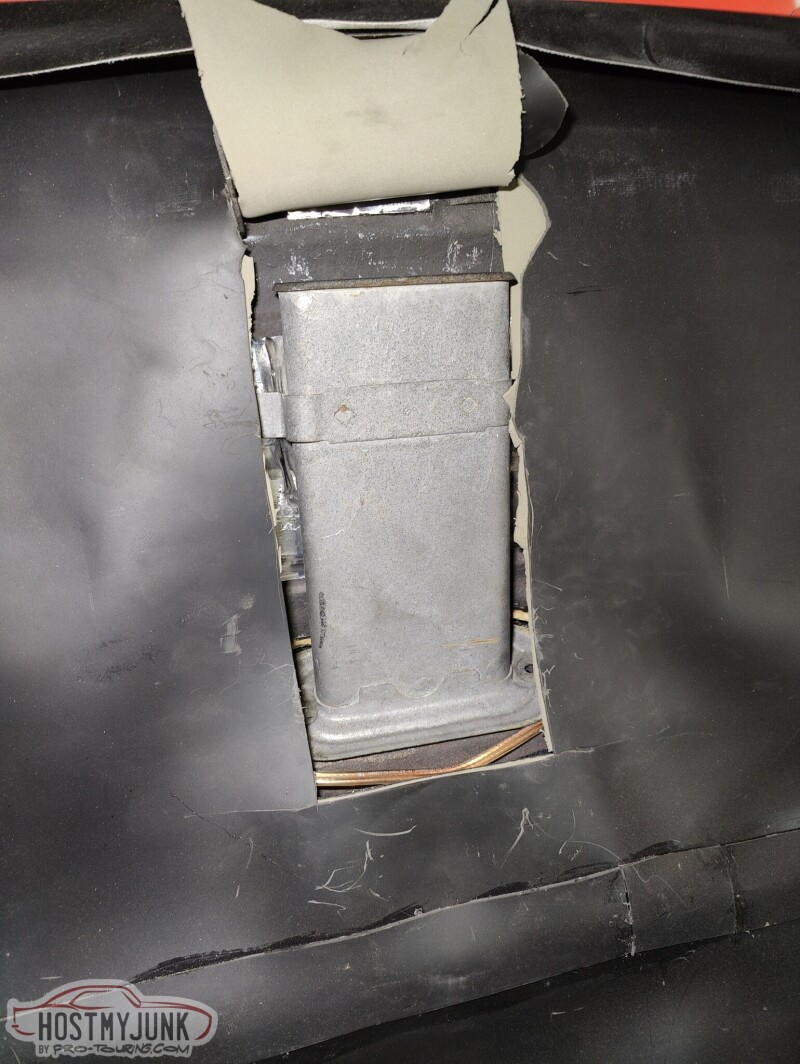
I sealed it against the body with some butyl rope.
Here you can see where the lines exit, just above the rear crossmember.
I also played around with the new gauges.
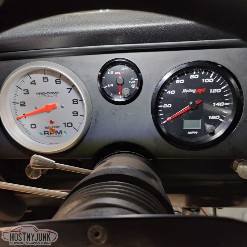
It is a little frustrating that the Holley gauges are 4" instead of 5", so something has to be done about that...The fuel lever gauge fit great into the 2 1/16" hole.
Andrew
But I needed access so that I could install this...
It is a OEM fuel vapor separator. I plan to vent the tank though this and then into a small charcoal canister. That should keep most of the fuel vapors at bay.
I sealed it against the body with some butyl rope.
Here you can see where the lines exit, just above the rear crossmember.
I also played around with the new gauges.
It is a little frustrating that the Holley gauges are 4" instead of 5", so something has to be done about that...The fuel lever gauge fit great into the 2 1/16" hole.
Andrew
The following users liked this post:
C5_Pete (03-16-2023)
03-18-2023 | 09:37 AM
#315
Thread Starter
Joined: Mar 2003
Posts: 10,244
Likes: 1,533
From: The City of Fountains
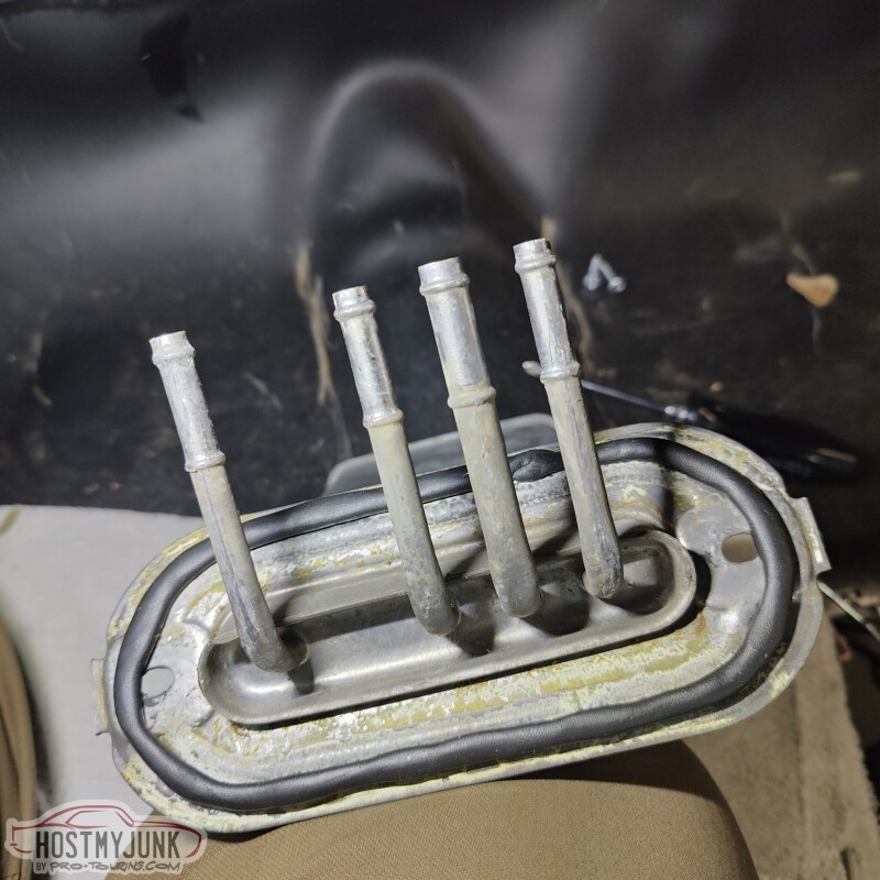
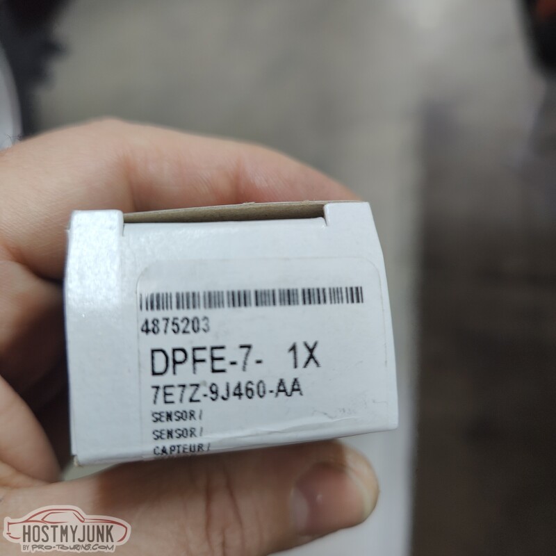
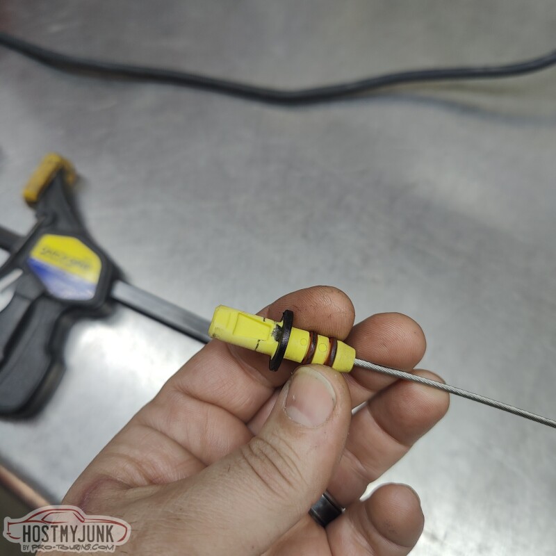
I like to repurpose OEM parts as part of my builds. I am not sure how I ran across this part, but it is from a 2008 Ford F250 with the PowerStroke engine.
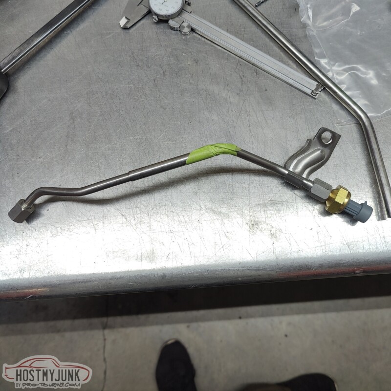
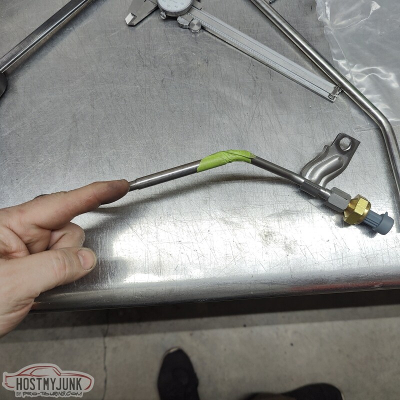
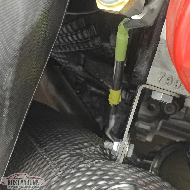
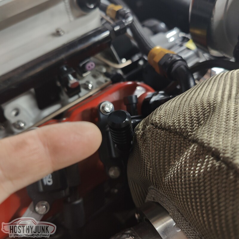
This is what Ford uses for the exhaust pressure sensor, and I figured I can use it for the same purpose. In this picture, the tube has been cut and a sleeve installed over the cut. The sleeve ends where the green tape is and where my finger is pointing.
This is the sensor part number. From what I have been able to gather, it is a 0-54psi sensor.
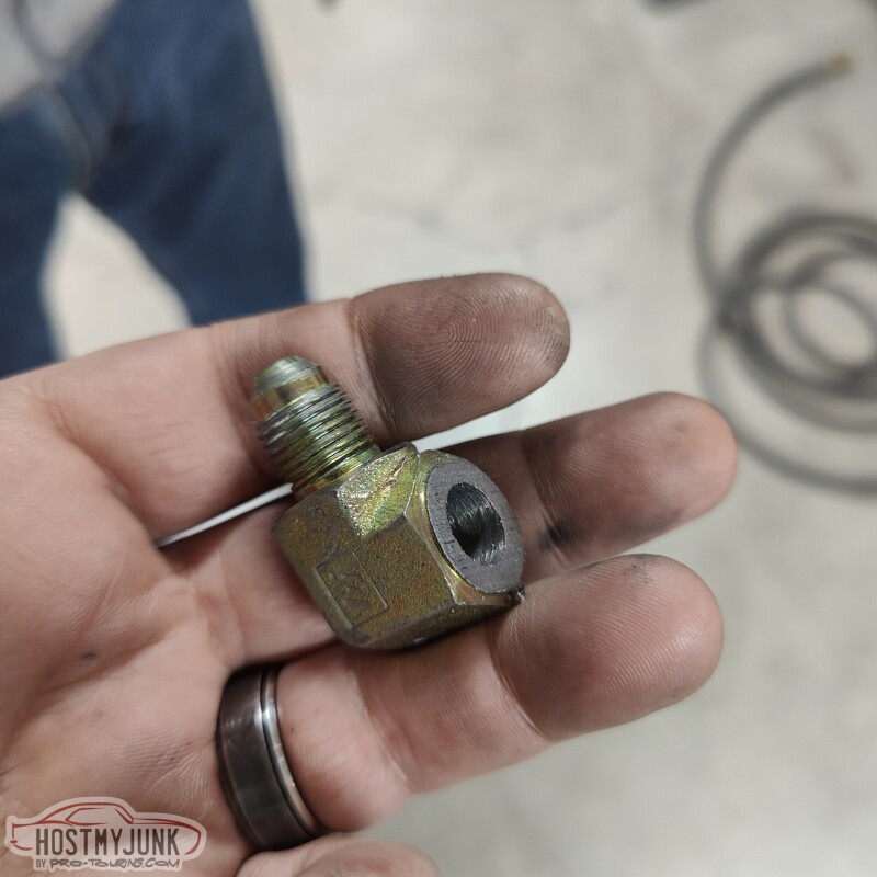
The tube is stainless and 5/16" diameter and it uses 37 degree flares with tube sleeves and nuts at both ends. That size tubing translates to an -AN5, which is not super common. Luckily, I had this 90 degree NPT to -AN5 adapter that I was using on the old tank for the return line. The NPT side has been cut off and Vic turned it down in the lathe to make a -AN5 male weld fitting.
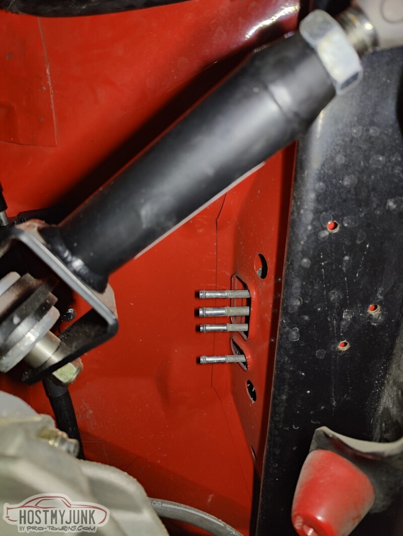
Here you can see where the fitting is going to go. Yes, the first hole was way off...
The whole assembly is bolted to one of the holes on the back of the heads...
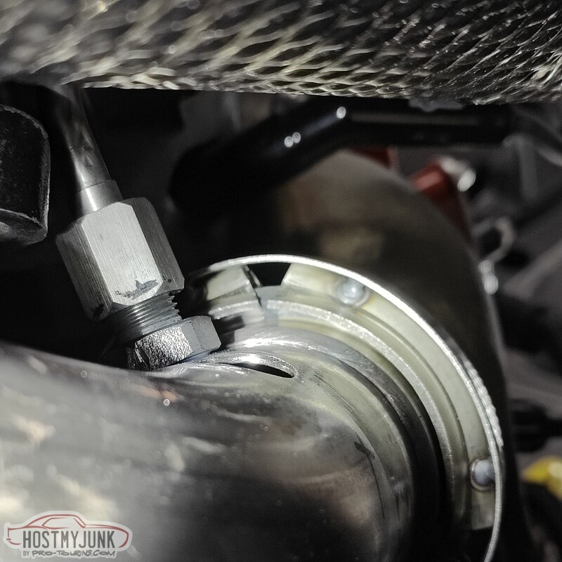
and the tube extends down to the crossover pipe...
Once the tube was the right length and clocked correctly, the sleeve was welded to the tube.
Andrew
This is what Ford uses for the exhaust pressure sensor, and I figured I can use it for the same purpose. In this picture, the tube has been cut and a sleeve installed over the cut. The sleeve ends where the green tape is and where my finger is pointing.
This is the sensor part number. From what I have been able to gather, it is a 0-54psi sensor.
The tube is stainless and 5/16" diameter and it uses 37 degree flares with tube sleeves and nuts at both ends. That size tubing translates to an -AN5, which is not super common. Luckily, I had this 90 degree NPT to -AN5 adapter that I was using on the old tank for the return line. The NPT side has been cut off and Vic turned it down in the lathe to make a -AN5 male weld fitting.
Here you can see where the fitting is going to go. Yes, the first hole was way off...
The whole assembly is bolted to one of the holes on the back of the heads...
and the tube extends down to the crossover pipe...
Once the tube was the right length and clocked correctly, the sleeve was welded to the tube.
Andrew
The following 3 users liked this post by Project GatTagO:
The following users liked this post:
Project GatTagO (03-18-2023)
03-18-2023 | 06:35 PM
#317
Thread Starter
Joined: Mar 2003
Posts: 10,244
Likes: 1,533
From: The City of Fountains
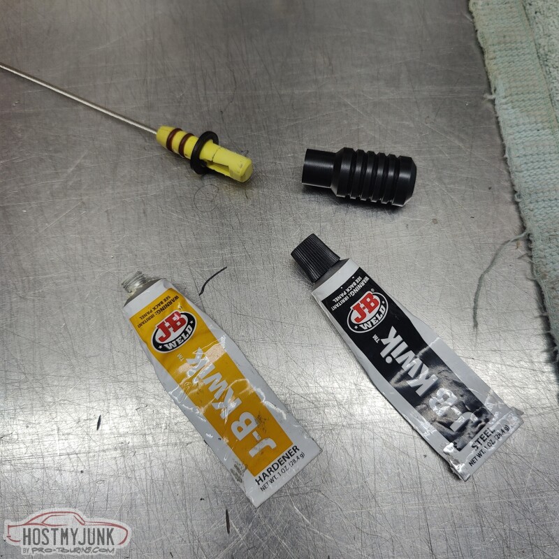
I arrived at Vic's this morning and found that he had already stuck the stock dipstick into the lathe and got rid of the ugly yellow dipstick handle.
He also took a piece of Delrin that he had on hand and made a new new dipstick handle, which is much more appealing.

Once the parts were ready, they were cleaned and mated together with some JB Weld.
Much better...
Here it is, in case you didn't notice it.
I also mounted the AC condenser in its location and removed the protective cardboard from the radiator.
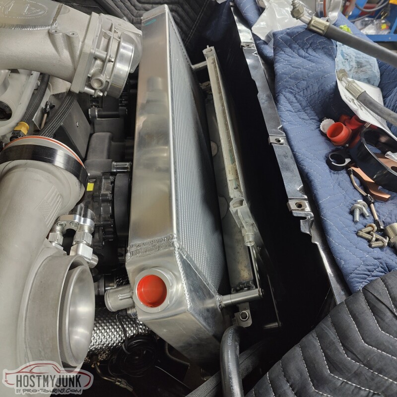
I will have the AC and the heater plumbing sorted pretty soon.
Andrew
He also took a piece of Delrin that he had on hand and made a new new dipstick handle, which is much more appealing.
Once the parts were ready, they were cleaned and mated together with some JB Weld.
Much better...
Here it is, in case you didn't notice it.
I also mounted the AC condenser in its location and removed the protective cardboard from the radiator.
I will have the AC and the heater plumbing sorted pretty soon.
Andrew
The following users liked this post:
C5_Pete (03-19-2023)
03-21-2023 | 09:42 PM
#318
Thread Starter
Joined: Mar 2003
Posts: 10,244
Likes: 1,533
From: The City of Fountains
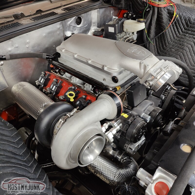
I decided that I wanted to rotate the Holley Lo-Ram front to back, which will put the MAP sensors in the front.
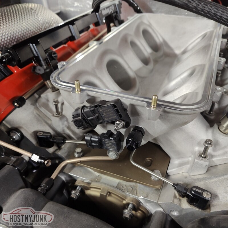
The main purpose for rotating the manifold is to clean up the area behind the intake and have the ability to use the stock oil pressure sensor in the stock location. I should have done this at the beginning...
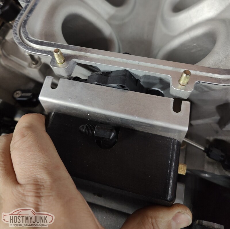
Rotating the manifold involved a bunch of changes. One of them being the plate that holds the boost solenoids. It still fits, but it had to be cut to clear the Bosch TMAP sensor.
I also picked up some AC hose ends locally. The top hose that goes to the condenser is from the compressor.
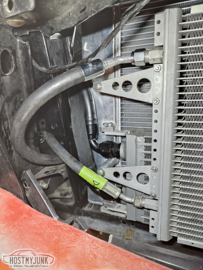
The lower hose goes to the dryer. I have a new dryer on the way along with a AC pressure sensor, which will replace the binary switch. The AC compressor will be controlled by the Dominator ECU and the HardWire PDM.
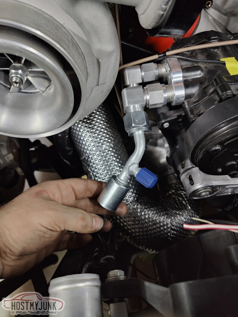
I got a 45 degree fitting for the #10 hose that goes from the evaporator to the front port on the compressor. The rear port on the compressor is a #8, and goes to the top of the condenser.
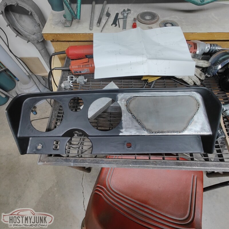
I also took out the dash insert.
With the dash insert out, I will be able to get to all of the wiring and ducting behind the dash, without actually having to pull the dash out. The 3 gauges that are front and center will be the Holley CAN RPM and Speedo, as well as a small fuel level gauge.
The holes on the right will be filled in. The 6.86" Holley Pro-dash will go where the three larger gauges used to be and below that will be two AC vents.
Andrew
The main purpose for rotating the manifold is to clean up the area behind the intake and have the ability to use the stock oil pressure sensor in the stock location. I should have done this at the beginning...
Rotating the manifold involved a bunch of changes. One of them being the plate that holds the boost solenoids. It still fits, but it had to be cut to clear the Bosch TMAP sensor.
I also picked up some AC hose ends locally. The top hose that goes to the condenser is from the compressor.
The lower hose goes to the dryer. I have a new dryer on the way along with a AC pressure sensor, which will replace the binary switch. The AC compressor will be controlled by the Dominator ECU and the HardWire PDM.
I got a 45 degree fitting for the #10 hose that goes from the evaporator to the front port on the compressor. The rear port on the compressor is a #8, and goes to the top of the condenser.
I also took out the dash insert.
With the dash insert out, I will be able to get to all of the wiring and ducting behind the dash, without actually having to pull the dash out. The 3 gauges that are front and center will be the Holley CAN RPM and Speedo, as well as a small fuel level gauge.
The holes on the right will be filled in. The 6.86" Holley Pro-dash will go where the three larger gauges used to be and below that will be two AC vents.
Andrew
The following users liked this post:
C5_Pete (03-22-2023)
03-23-2023 | 09:26 PM
#319
Thread Starter
Joined: Mar 2003
Posts: 10,244
Likes: 1,533
From: The City of Fountains
This is a small update with, hopefully, useful information.
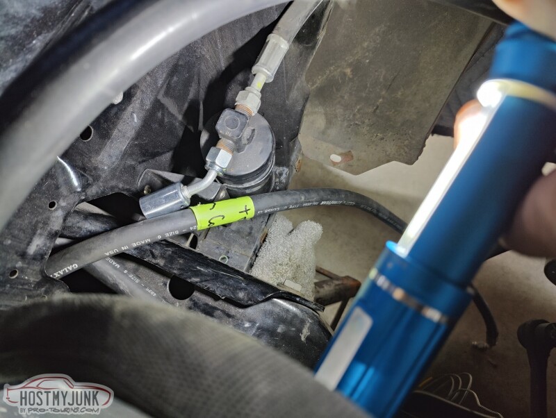
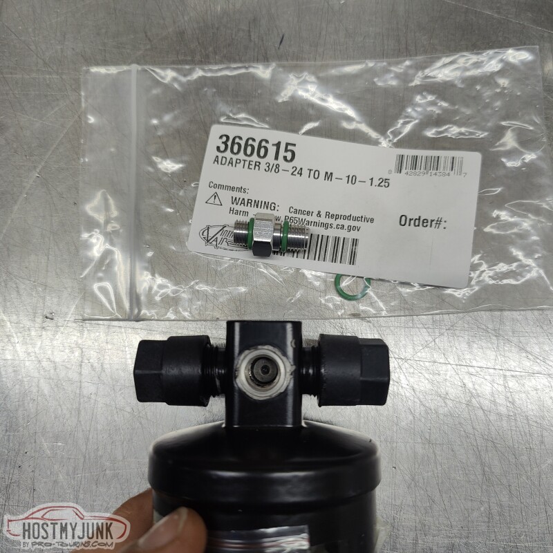
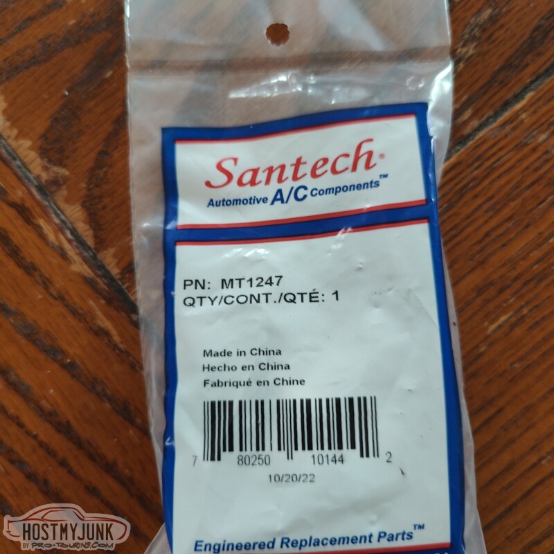
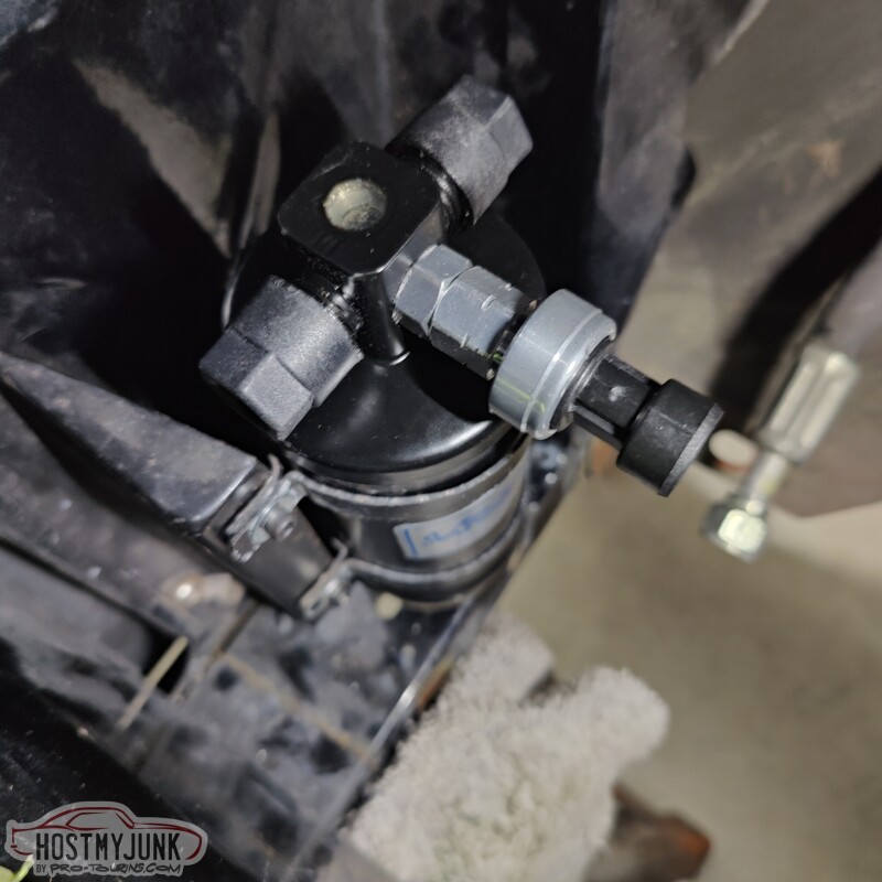
Since the Holley EFI will be controlling the AC compressor, I wanted to use an AC pressure sensor. This is a little adapter that VA sells just for that purpose. Also pictured is a new VA dryer, where the fitting goes.
This is the AC pressure sensor that I am using. The main reason that I picked it is because I have the output configuration for it.
This is the new dryer, installed in its location on the radiator core support.
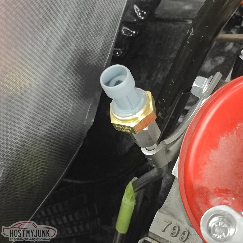
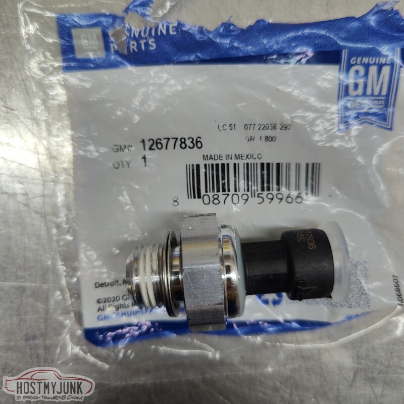
A lot of people ask me which oil pressure sensor I like to use on Gen 4 engines with Holley EFI. This is the one, and the connector on the Holley EFI harness has the correct connector. It is a 135psi sensor.
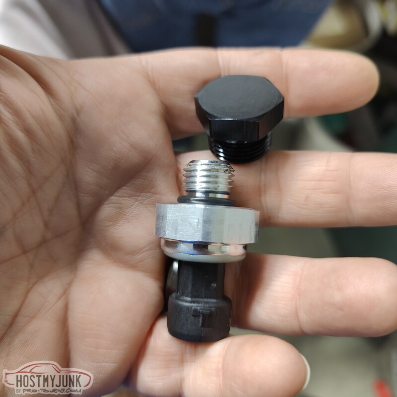
This sensor looks similar, but it has a 12mm thread on it, instead of the 16mm thread on the sensor shown above. I had this end cap for the Holley fuel rail, so I had an idea...
I told my idea to Vic and a little while later my idea was made reality.
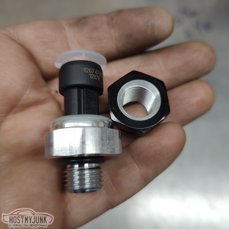
Vic drilled and tapped the cap for the 12mm thread and a groove for the o-ring to seat against.
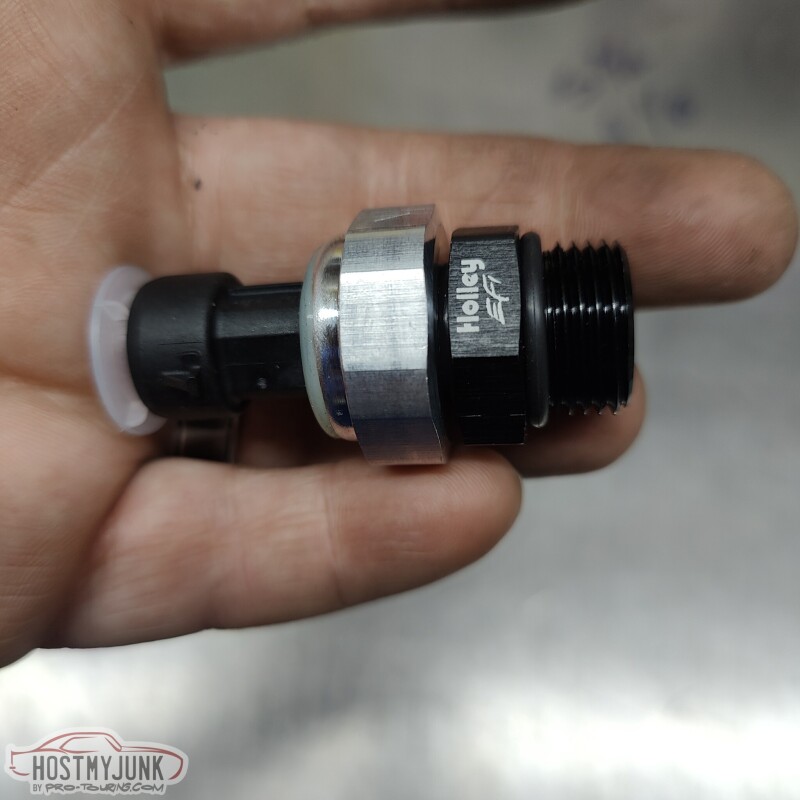
I installed it in the rear of the driver's side fuel rail. So I have a fuel pressure and temperature sensor after the fuel filter and this sensor in the rail, mostly because I can.
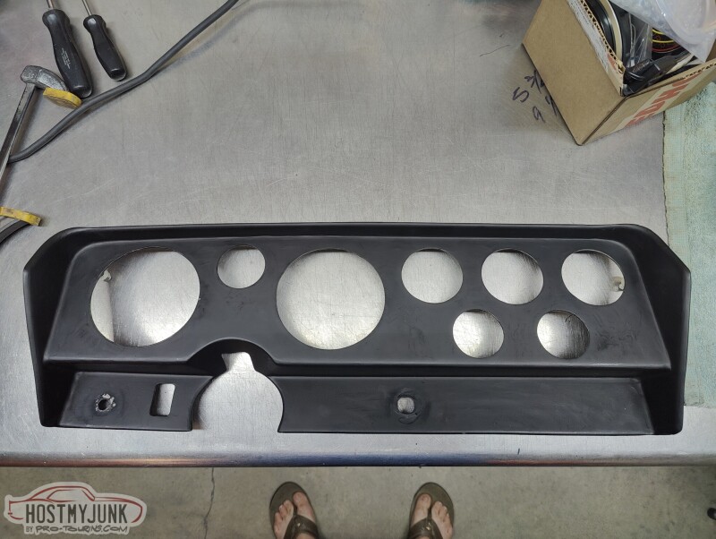
Vic is also making progress on modifying the dash insert to use with the Holley Pro-Dash.
The small hole to the right of the steering column will also get filled.
Andrew
Since the Holley EFI will be controlling the AC compressor, I wanted to use an AC pressure sensor. This is a little adapter that VA sells just for that purpose. Also pictured is a new VA dryer, where the fitting goes.
This is the AC pressure sensor that I am using. The main reason that I picked it is because I have the output configuration for it.
This is the new dryer, installed in its location on the radiator core support.
A lot of people ask me which oil pressure sensor I like to use on Gen 4 engines with Holley EFI. This is the one, and the connector on the Holley EFI harness has the correct connector. It is a 135psi sensor.
This sensor looks similar, but it has a 12mm thread on it, instead of the 16mm thread on the sensor shown above. I had this end cap for the Holley fuel rail, so I had an idea...
I told my idea to Vic and a little while later my idea was made reality.
Vic drilled and tapped the cap for the 12mm thread and a groove for the o-ring to seat against.
I installed it in the rear of the driver's side fuel rail. So I have a fuel pressure and temperature sensor after the fuel filter and this sensor in the rail, mostly because I can.
Vic is also making progress on modifying the dash insert to use with the Holley Pro-Dash.
The small hole to the right of the steering column will also get filled.
Andrew
03-24-2023 | 08:38 PM
#320
Thread Starter
Joined: Mar 2003
Posts: 10,244
Likes: 1,533
From: The City of Fountains
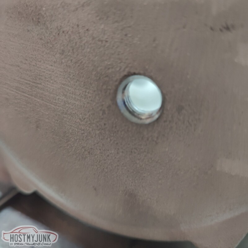
Since I decided to rotate the Holley Lo-Ram base front to back, I needed to add a fitting for the catch can. Instead of using the typical NPT to AN adapter, I used this straight thread ORB adapter.
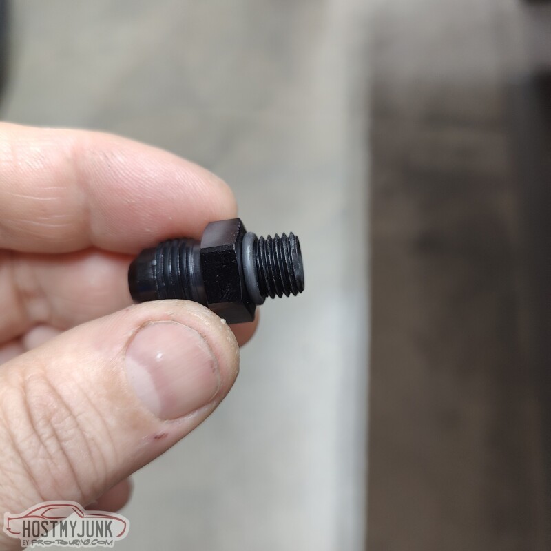
All that is needed is a little counter-sink for the o-ring to seal against. Sorted...
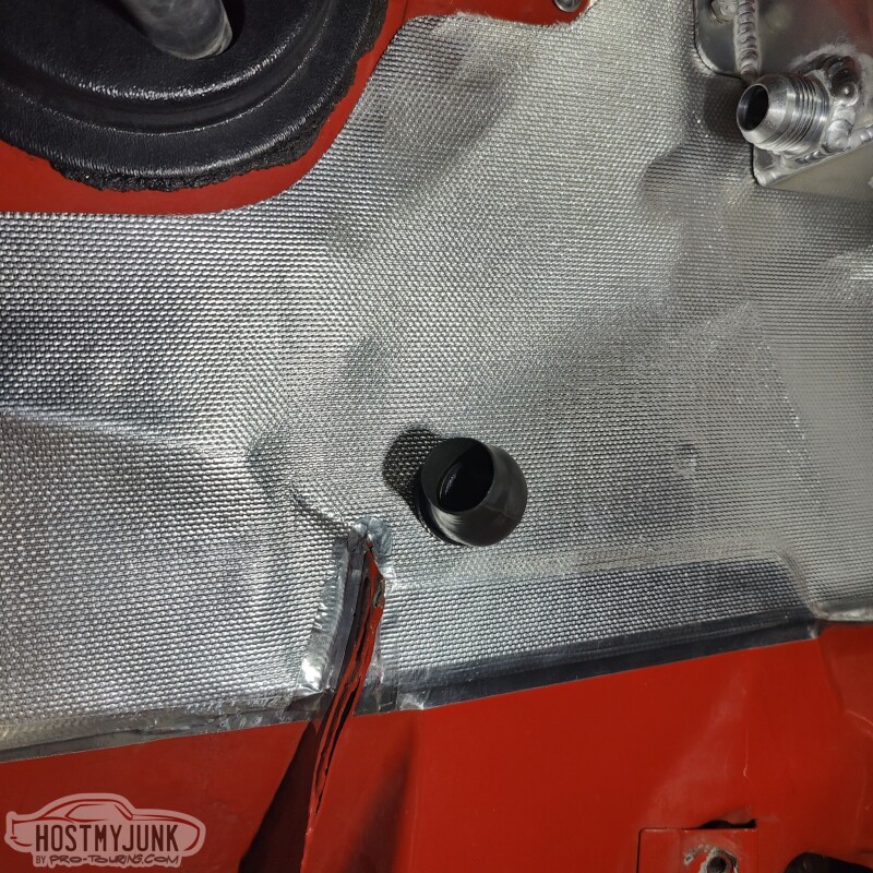
I needed a pass through for some wires to come through the firewall, low on the passenger side. This pass through is for wiring the heater control valve, fan speed signal, AC pressure sensor, EGT probe, and the dome pressure sensor.
I enlarged an existing hole to 1" using a step drill and...
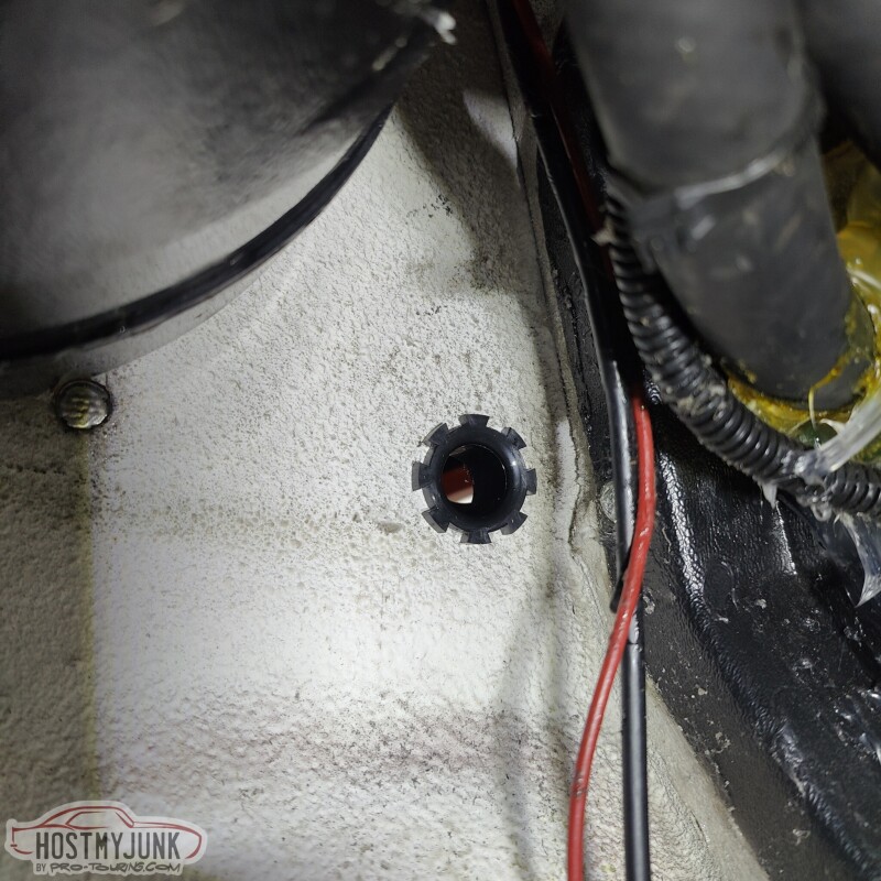
used a TE Connectivity 90 degree heat shrink boot passthrough.
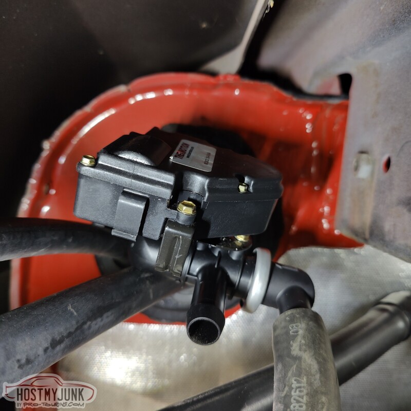
This is the 4 port, electronic heater control valve that I am using. It is sold by Thermotion. This will allow the coolant to flow through the heater core circuit when the valve is closed to shut the coolant flow through the heater core, when the AC is being used.
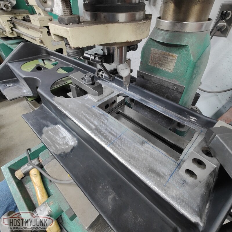
Vic also finished filling the holes in the dash. He then fixtures the dash in the mill to make the opening for the Holley 6.86" Pro-Dash.
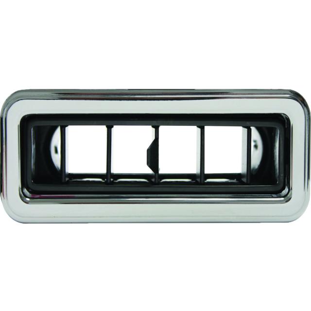
Below the dash will be two of these VA dash vents:
Andrew
All that is needed is a little counter-sink for the o-ring to seal against. Sorted...
I needed a pass through for some wires to come through the firewall, low on the passenger side. This pass through is for wiring the heater control valve, fan speed signal, AC pressure sensor, EGT probe, and the dome pressure sensor.
I enlarged an existing hole to 1" using a step drill and...
used a TE Connectivity 90 degree heat shrink boot passthrough.
This is the 4 port, electronic heater control valve that I am using. It is sold by Thermotion. This will allow the coolant to flow through the heater core circuit when the valve is closed to shut the coolant flow through the heater core, when the AC is being used.
Vic also finished filling the holes in the dash. He then fixtures the dash in the mill to make the opening for the Holley 6.86" Pro-Dash.
Below the dash will be two of these VA dash vents:
Andrew