
First turbo build, 70 GTO...
 05-02-2023 | 12:58 PM
#341

The following users liked this post:
Project GatTagO (05-02-2023)
05-02-2023 | 03:22 PM
#342
Thread Starter

Joined: Mar 2003
Posts: 10,244
Likes: 1,531
From: The City of Fountains
Andrew
05-02-2023 | 04:25 PM
#343
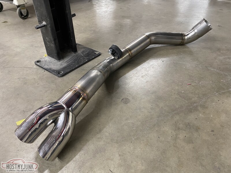
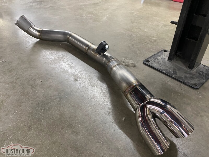
There are many ways to plumb that exhaust valve. This is what made the most sense to me and my purposes. I want it quiet when both sides are open and quieter when one side is shut off. Whether this works or not remains to be seen. I admit that this might be a complete waste of time and money.
Andrew
Andrew
05-02-2023 | 04:34 PM
#344
Thread Starter
Joined: Mar 2003
Posts: 10,244
Likes: 1,531
From: The City of Fountains
I'm pretty sure it'll make zero difference. Mine is pretty quiet just straight piped all the way to the tailpipe bypassing the muffler. I can barely hear a difference with it open and closed. I think yours will not even be perceivable. just my .02 from having just finished doing mine.
I'm not doubting you. When it is running I'll be able to do some sound level testing and I'll be happy to post the results. Even if it makes -3db difference, that'll be huge.
Andrew
The following users liked this post:
Kfxguy (05-03-2023)
05-02-2023 | 05:07 PM
#345


The following users liked this post:
Project GatTagO (05-02-2023)
05-02-2023 | 05:14 PM
#346
Thread Starter
Joined: Mar 2003
Posts: 10,244
Likes: 1,531
From: The City of Fountains
I see a dual inlet muffler but you have a single pipe splitting off at the Y pipe with the valve in place.
How's the exhaust path different when the cutout is closed, besides having to make two extra turns?
Andrew
05-02-2023 | 06:05 PM
#347
I don't know what kind of muffler that is, but I don't see why yours should or would sound different. I don't even understand what makes your set up dual mode...
I see a dual inlet muffler but you have a single pipe splitting off at the Y pipe with the valve in place.
How's the exhaust path different when the cutout is closed, besides having to make two extra turns?
Andrew
I see a dual inlet muffler but you have a single pipe splitting off at the Y pipe with the valve in place.
How's the exhaust path different when the cutout is closed, besides having to make two extra turns?
Andrew
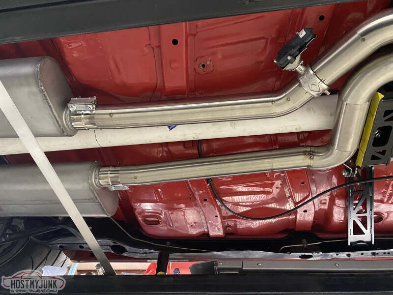
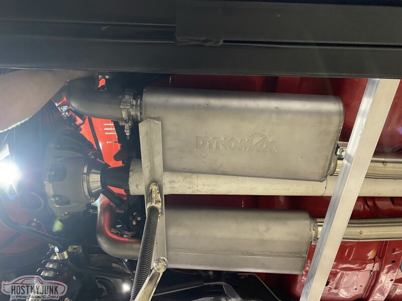
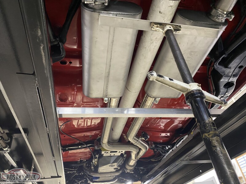
I built that muffler. Single 3.5� in. One side is muffled. The other straight through. Valve closed blocks the straight through side.


The following 2 users liked this post by Kfxguy:
Jimbo1367 (05-03-2023), Project GatTagO (05-02-2023)
The following 2 users liked this post by Project GatTagO:
02redchevy (05-04-2023), The BallSS (05-03-2023)
05-05-2023 | 08:44 PM
#349
Thread Starter
Joined: Mar 2003
Posts: 10,244
Likes: 1,531
From: The City of Fountains
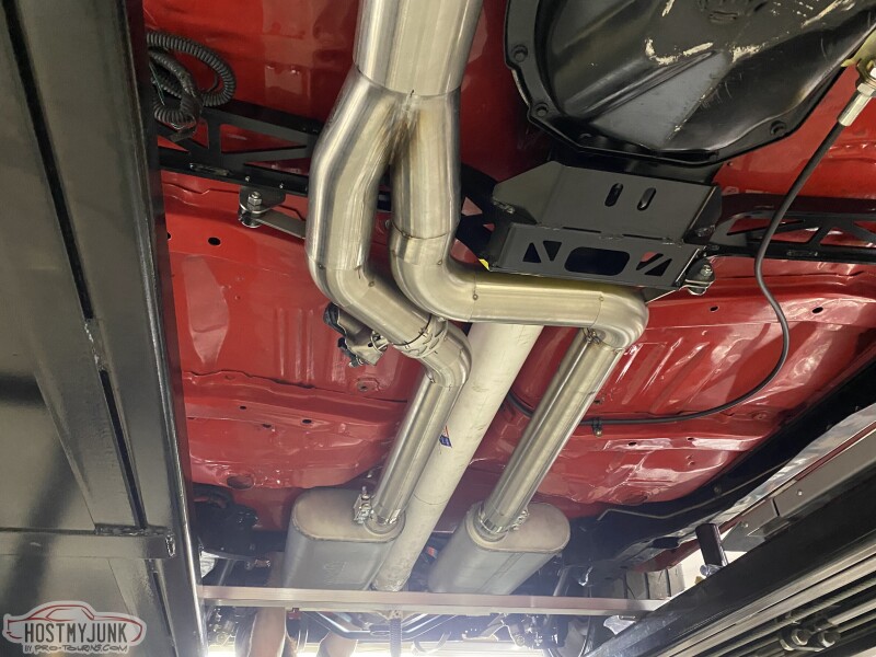
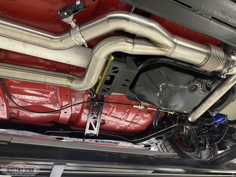
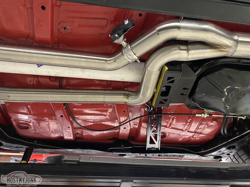
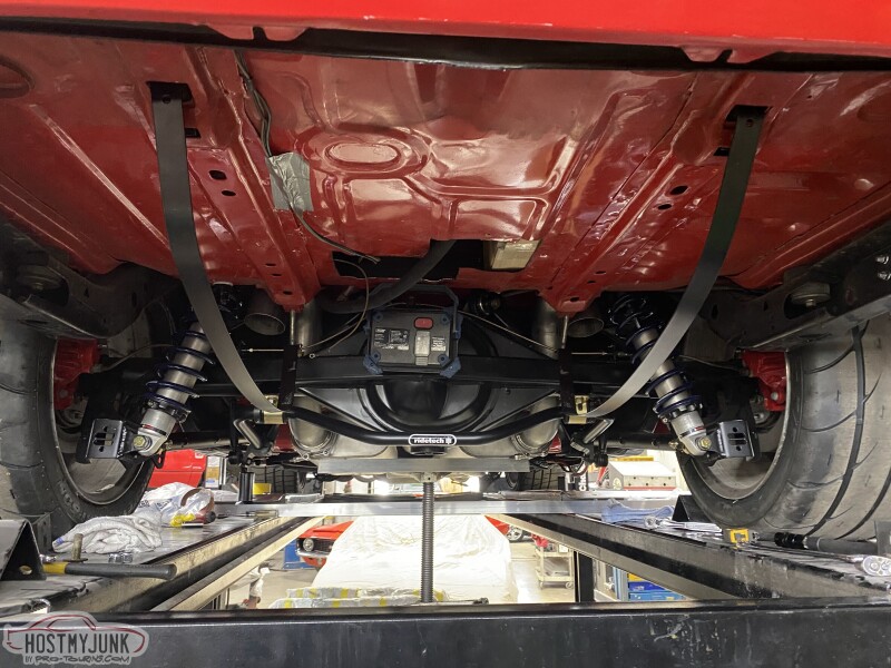
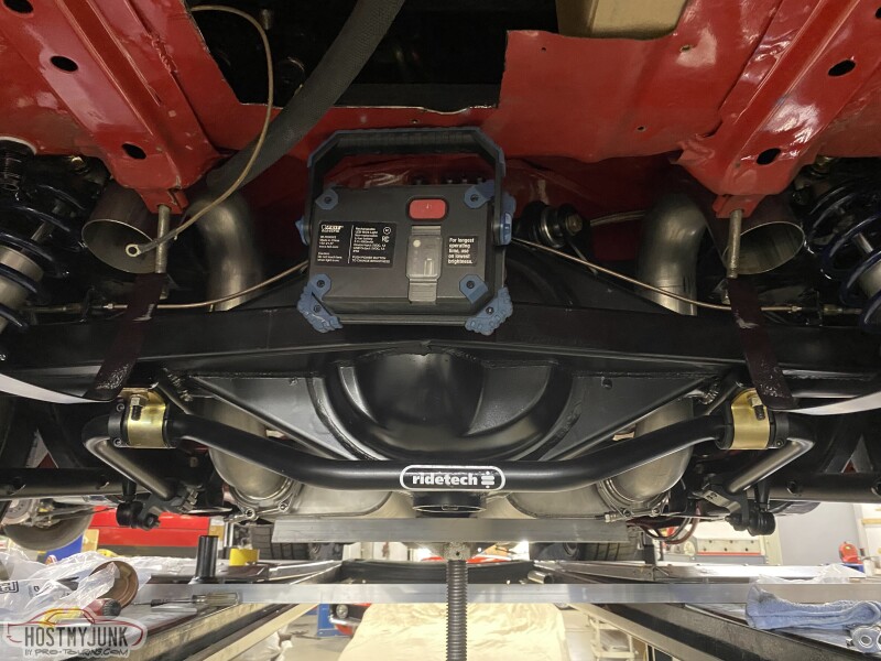
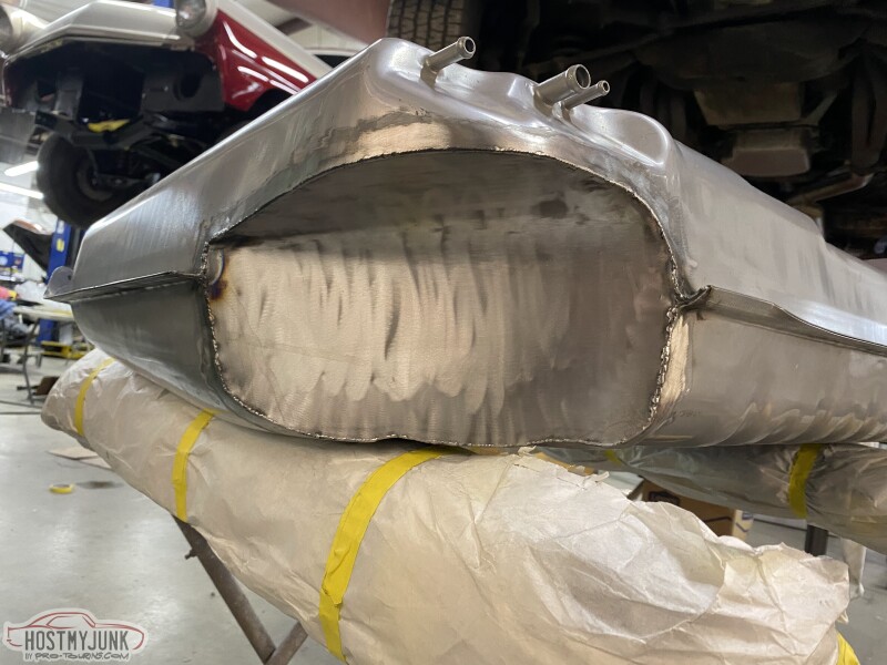
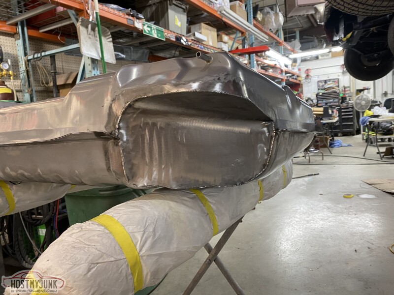
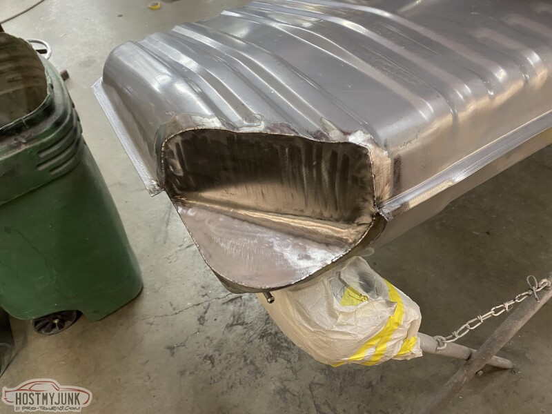
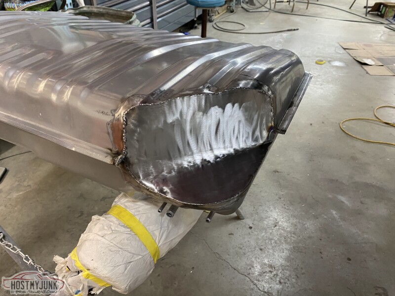
The exhaust and the gas tank are done. Here are the final pictures:
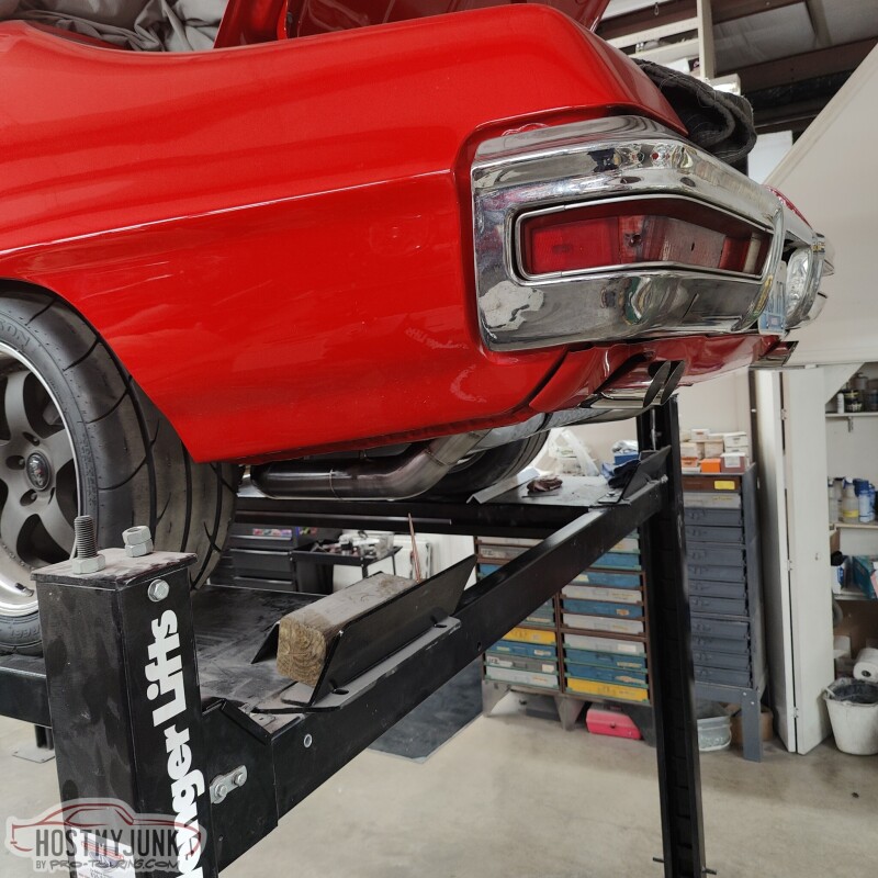
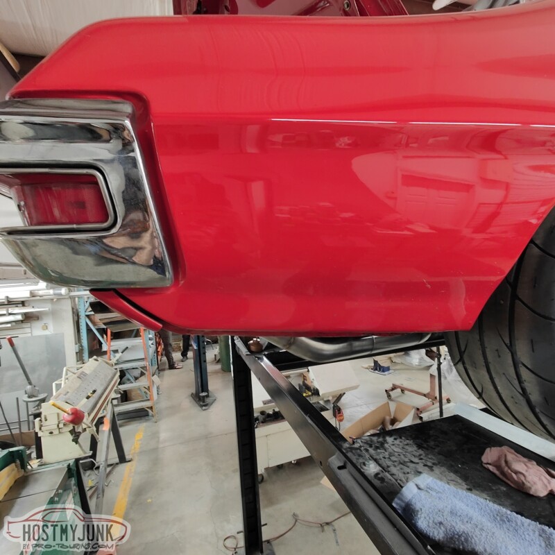
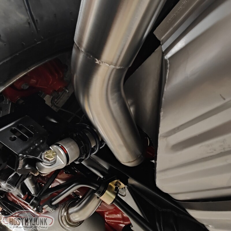
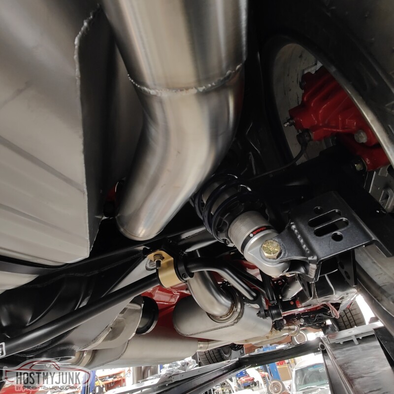
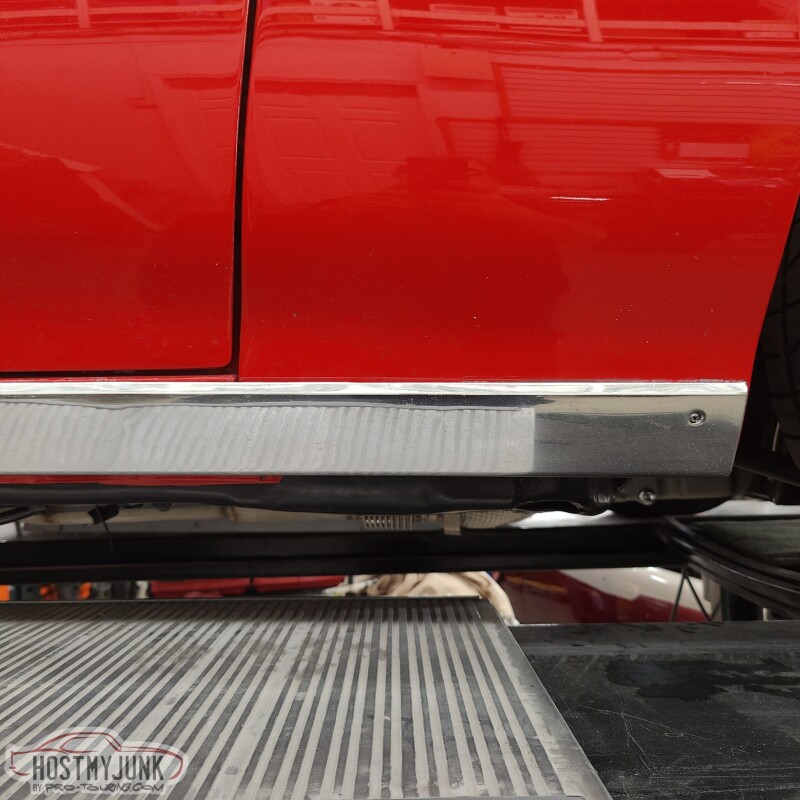
Rick from Hotrod Express also delivered the car to me this morning. Big thanks to my friend Tom, who came out to visit me. He helped to clean up and organize the garage so that I have a fighting chance of having the car drivable to LS Fest in September.
Andrew
Rick from Hotrod Express also delivered the car to me this morning. Big thanks to my friend Tom, who came out to visit me. He helped to clean up and organize the garage so that I have a fighting chance of having the car drivable to LS Fest in September.
Andrew
The following 3 users liked this post by Project GatTagO:
05-07-2023 | 12:02 PM
#350
Thread Starter
Joined: Mar 2003
Posts: 10,244
Likes: 1,531
From: The City of Fountains
Now that the car is back, I felt the need to go out there and do something, even if it is something small. Keeping in mind that I will be doing a lot of wiring under the dash, a removable steering wheel hub seemed like a good idea. My friend Tom had a NRG steering wheel hub on his 70 GTO and I really liked it.
I started by removing the horn button and removing the Momo steering wheel from the Momo hub.
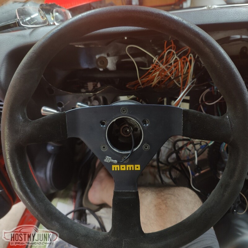
Then I removed the nut that was holding the hub in place.
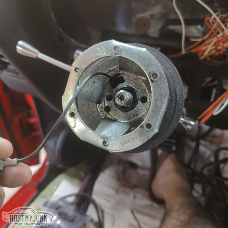
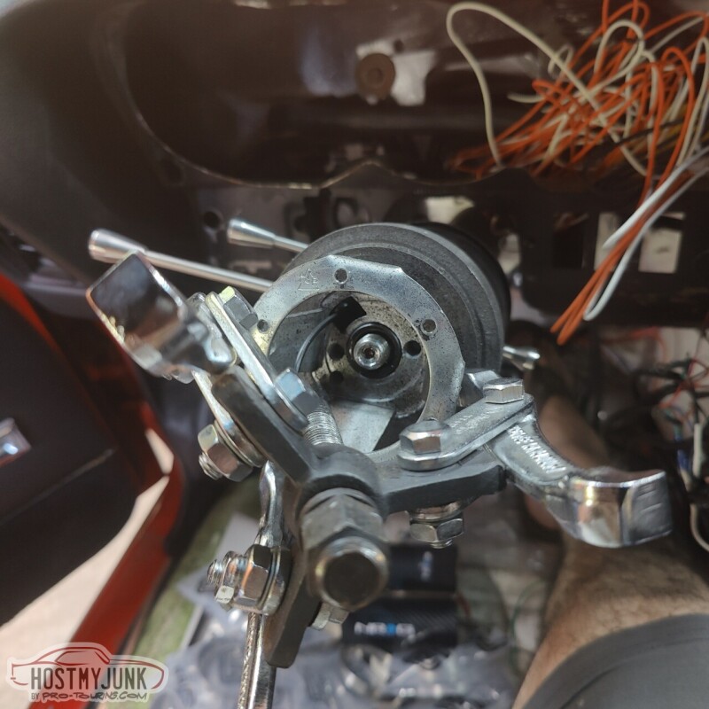
I had to use a 3 jaw puller to get the hub off the steering shaft.
This is the Momo adapter hub for a GM steering column. If anyone needs it, PM me.
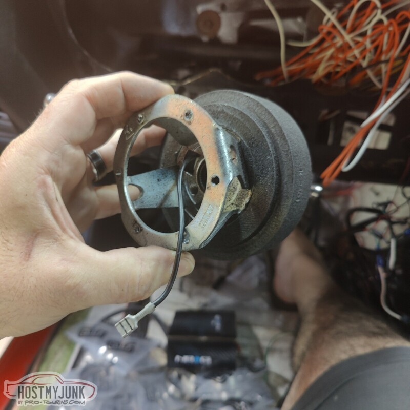
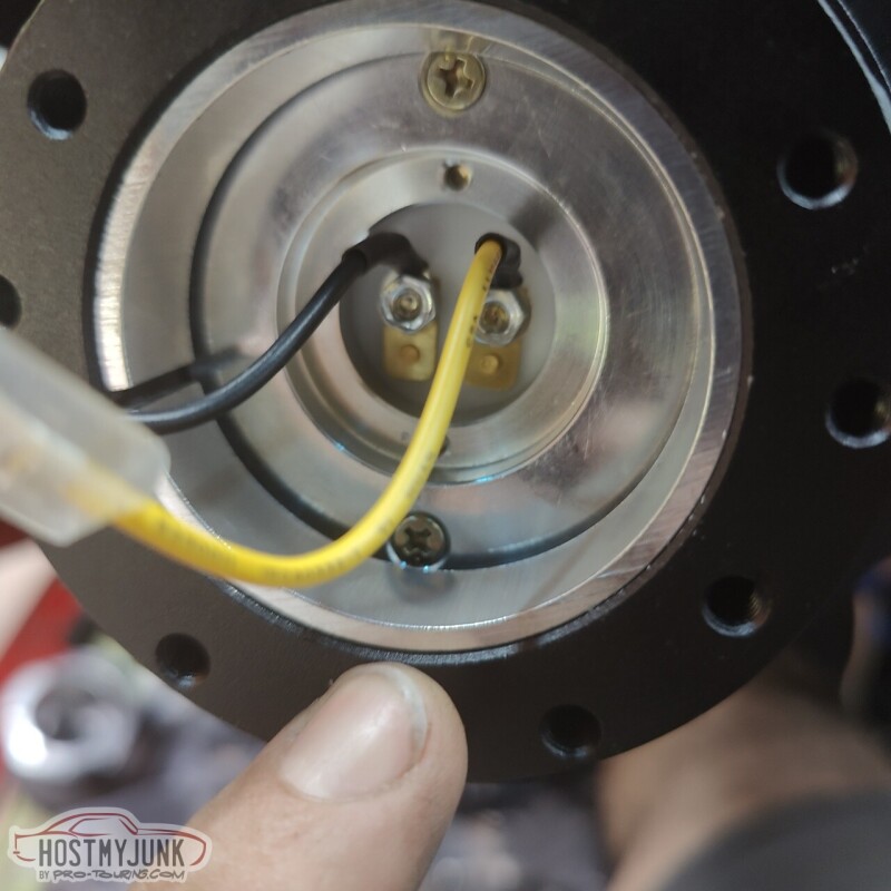
This is the new NRG hub. None of these parts came with any instructions. I am not exactly sure why the hub has a ground wire on it...
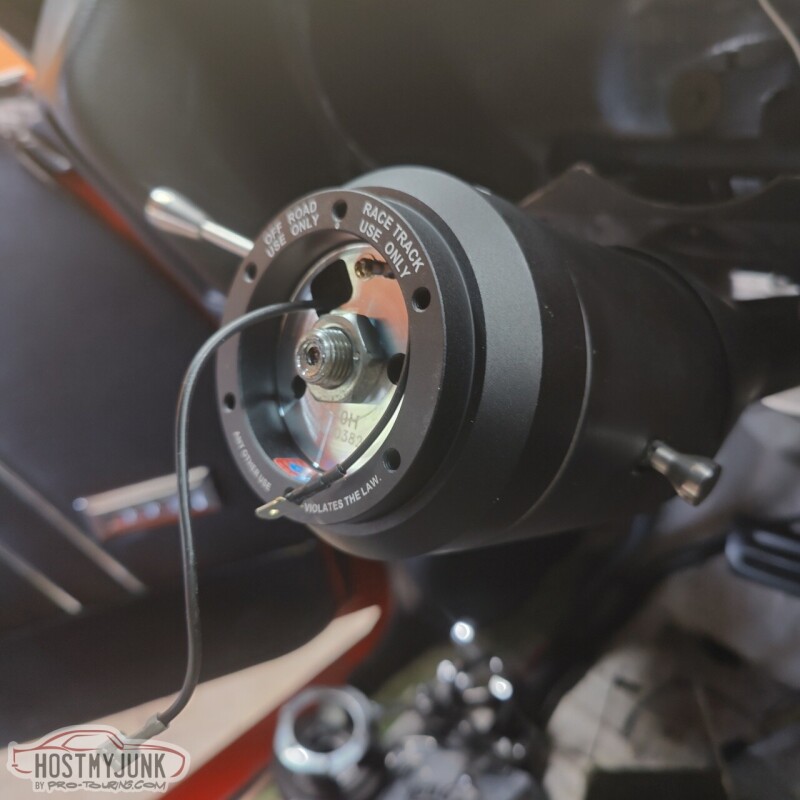
This is the hub that bolts to the steering wheel and snaps on the receiver that is bolted to the steering shaft.
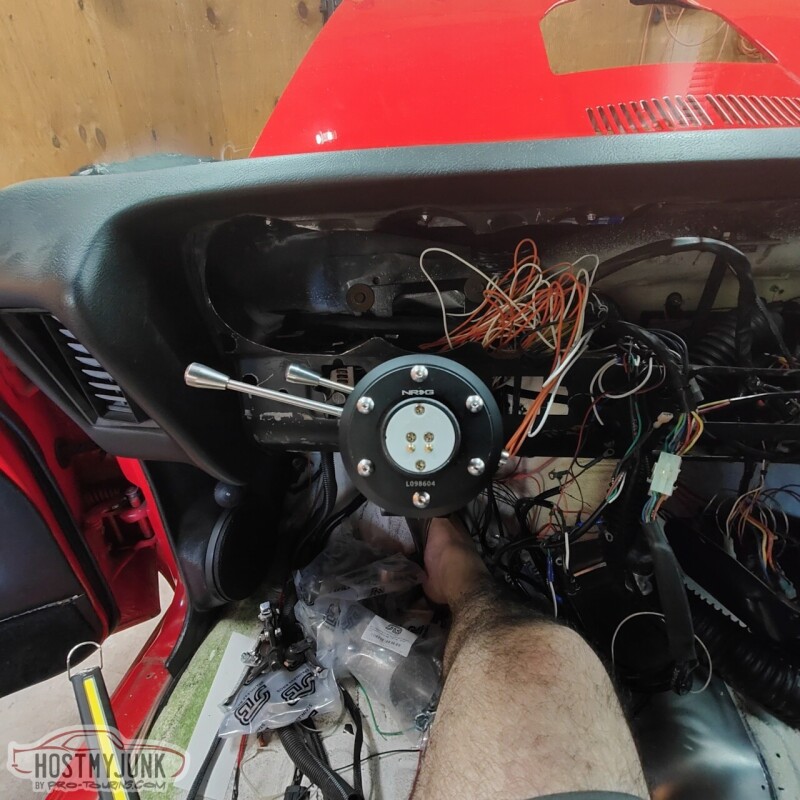
This is the finishd column with the receiver hub bolted to it.
To release the steering wheel from the column, the ring under the steering wheel is pulled back...
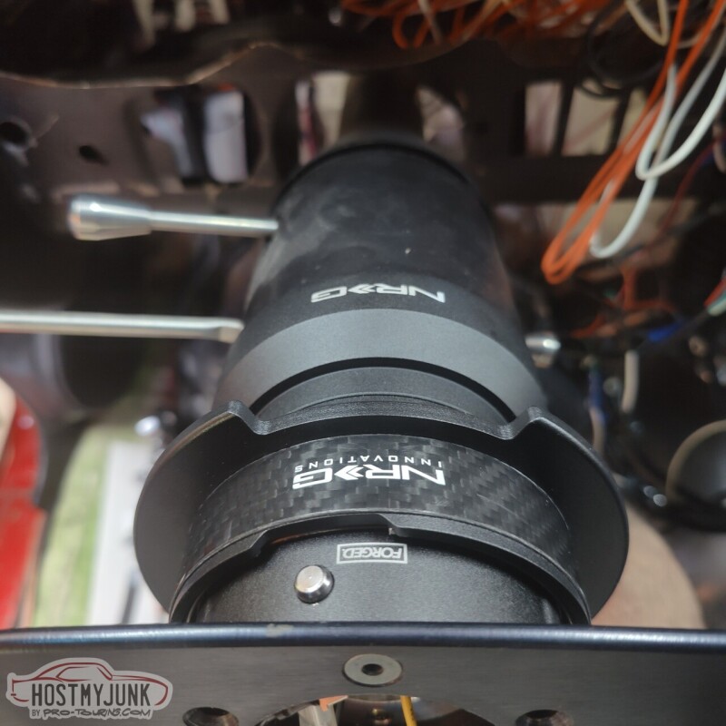
and the steering wheel comes off, along with the hub.
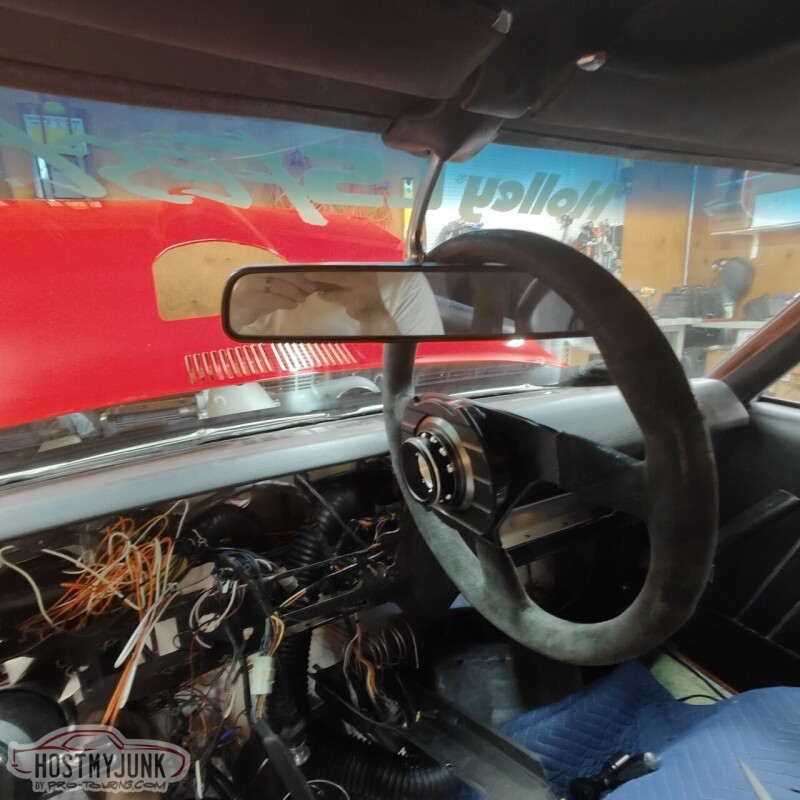
It will be a lot easier to work under the dash without the steering wheel in the way and it adds a small level of theft protection to the whole car.
Andrew
I started by removing the horn button and removing the Momo steering wheel from the Momo hub.
Then I removed the nut that was holding the hub in place.
I had to use a 3 jaw puller to get the hub off the steering shaft.
This is the Momo adapter hub for a GM steering column. If anyone needs it, PM me.
This is the new NRG hub. None of these parts came with any instructions. I am not exactly sure why the hub has a ground wire on it...
This is the hub that bolts to the steering wheel and snaps on the receiver that is bolted to the steering shaft.
This is the finishd column with the receiver hub bolted to it.
To release the steering wheel from the column, the ring under the steering wheel is pulled back...
and the steering wheel comes off, along with the hub.
It will be a lot easier to work under the dash without the steering wheel in the way and it adds a small level of theft protection to the whole car.
Andrew
05-12-2023 | 09:19 PM
#351
Thread Starter
Joined: Mar 2003
Posts: 10,244
Likes: 1,531
From: The City of Fountains
With the car now in my home garage I am able to spend a hour or two here and there and knock out little projects. Just like the old saying about how one might eat an elephant...
This picture is at a little bit of an odd angle, but it shows the finished turbo drain. While the car was at Hotrod Express, I asked Josh to put a bead in the 5/8" stainless tube that we used to extend the drain pipe. There is also a little section of 5/8" oil safe rubber hose that goes from the tube to the oil drain on the side of the oil pan. I used Gates heat shrink clamps on the hose. The stainless tube also has a silicone/fiberglass fire shield over it.
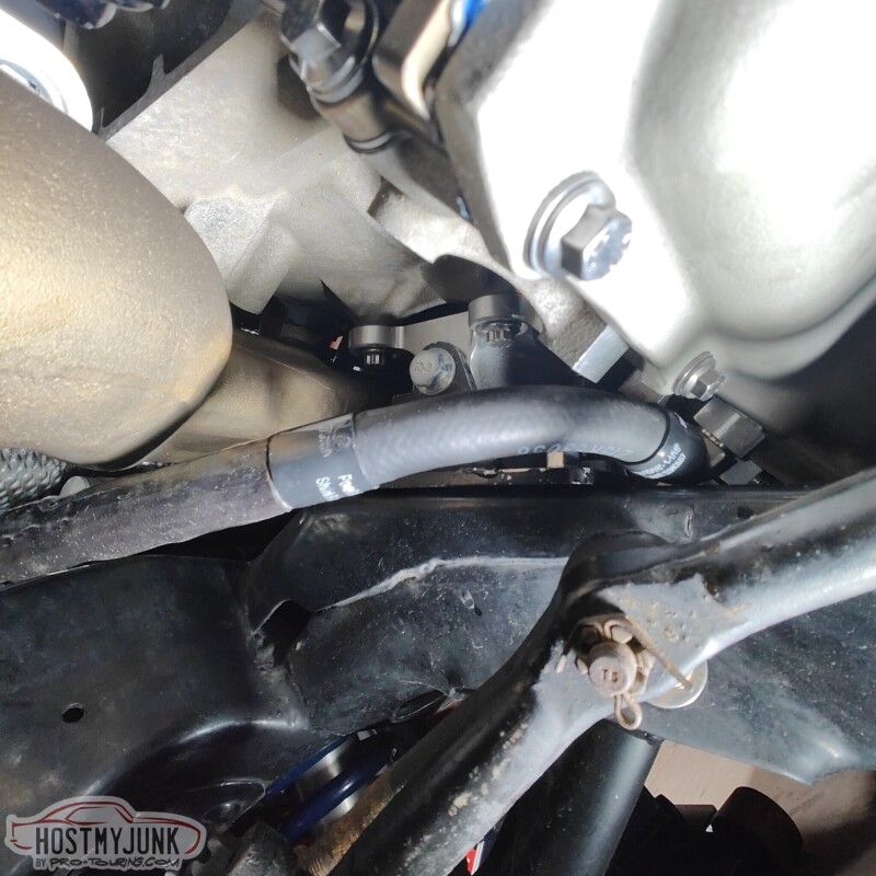
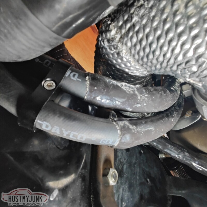
This picture is also at a bit of an odd angle, but it shows how the heater hoses come down from the water pump and under the up-pipe. There is fire sleeving over the top of the hose where it passes closest to the up-pipe.
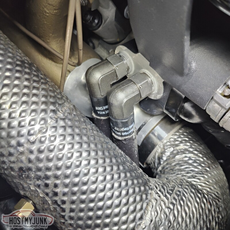
Here is the view from the top. Everything fits very closely together, but there is just enough room to turn fasteners and fittings. I also used the Gates heat shrink clamps on the heater hoses.
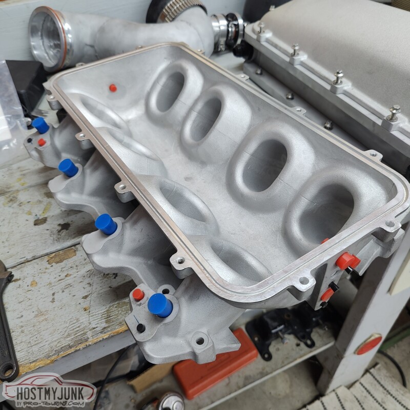
I took the intake off again so that I can clean everything and get it ready for Cerakote. Here I am mocking up the little silicone plugs that I will use to seal off machined and tapped holes.
She is looking more apart than before, but progress is being made.
Andrew
This picture is at a little bit of an odd angle, but it shows the finished turbo drain. While the car was at Hotrod Express, I asked Josh to put a bead in the 5/8" stainless tube that we used to extend the drain pipe. There is also a little section of 5/8" oil safe rubber hose that goes from the tube to the oil drain on the side of the oil pan. I used Gates heat shrink clamps on the hose. The stainless tube also has a silicone/fiberglass fire shield over it.
This picture is also at a bit of an odd angle, but it shows how the heater hoses come down from the water pump and under the up-pipe. There is fire sleeving over the top of the hose where it passes closest to the up-pipe.
Here is the view from the top. Everything fits very closely together, but there is just enough room to turn fasteners and fittings. I also used the Gates heat shrink clamps on the heater hoses.
I took the intake off again so that I can clean everything and get it ready for Cerakote. Here I am mocking up the little silicone plugs that I will use to seal off machined and tapped holes.
She is looking more apart than before, but progress is being made.
Andrew
05-13-2023 | 09:46 PM
#352
Thread Starter
Joined: Mar 2003
Posts: 10,244
Likes: 1,531
From: The City of Fountains
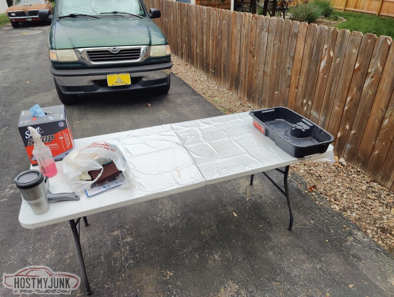
I have been watching the weather forecast, looking for a partly sunny day, with low wind and no rain. Well, today was that perfect day. I got started in the morning and started my Cerakote shop.
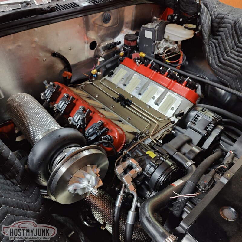
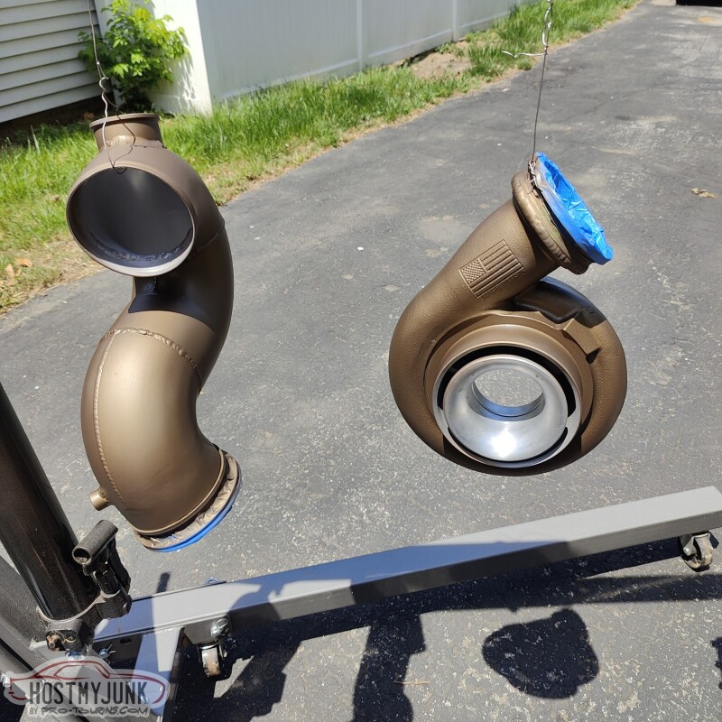
I had 4 parts to coat: compressor housing, charge pipe, intake lid and intake base (not pictured).
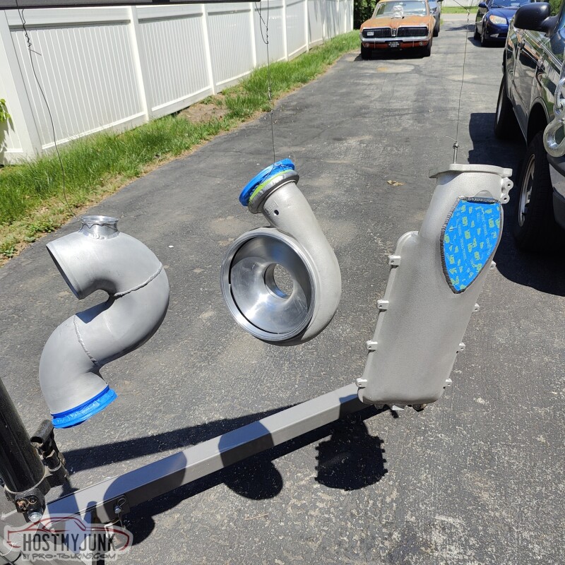
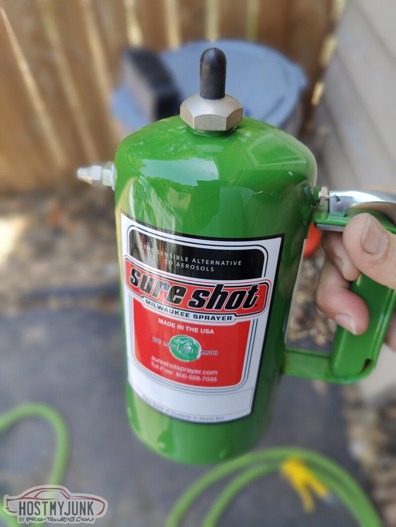
This guy was super helpful for cleaning. I filled it up with acetone, pressurized the can, and it sprayed a beautiful, fine mist that cleaned the parts well. Everything was already bead blasted before hand. I just sprayed everything down, used a red 3M pad to clean, and sprayed again. Then I used a MAP gas torch to heat the parts and evaporate all of the acetone.
I am using the Cerakite C coating, in the same burnt bronze color that I used on the valley cover and the front cover. You put down a light coat and immediately go over it with a heavier coat. It looks amazing in the sun, because the burnt bronze has a ton of gold and copper flakes in it.
I decided to leave the intercooler in raw aluminum, but I went over all of the surfaces with the red 3M pad to give it a brushed look.
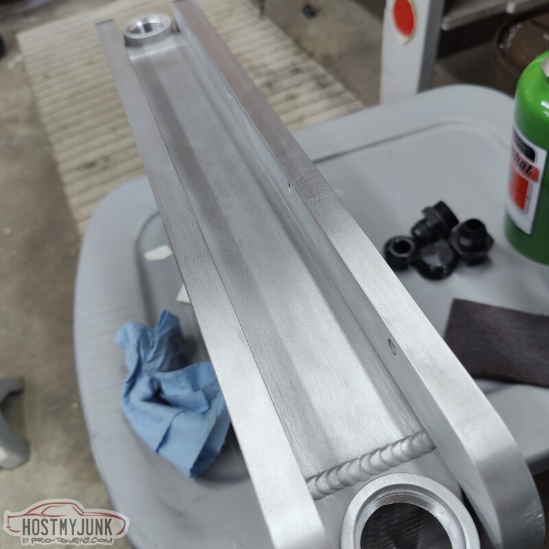
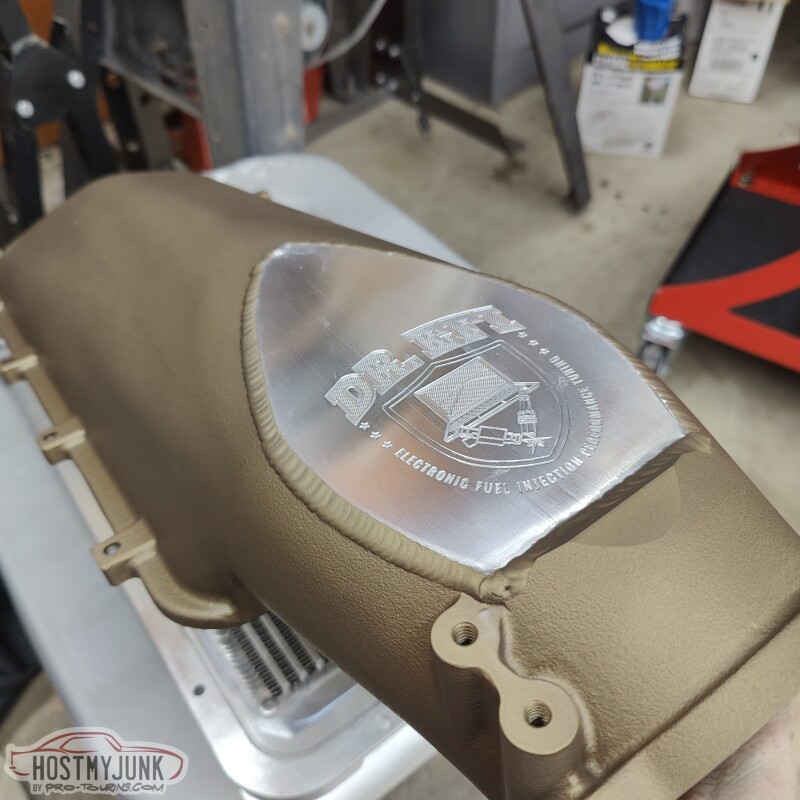
I taped off the plate with my business logo, so it would stay natural. The engraving would lose all the detail if I was to paint it.
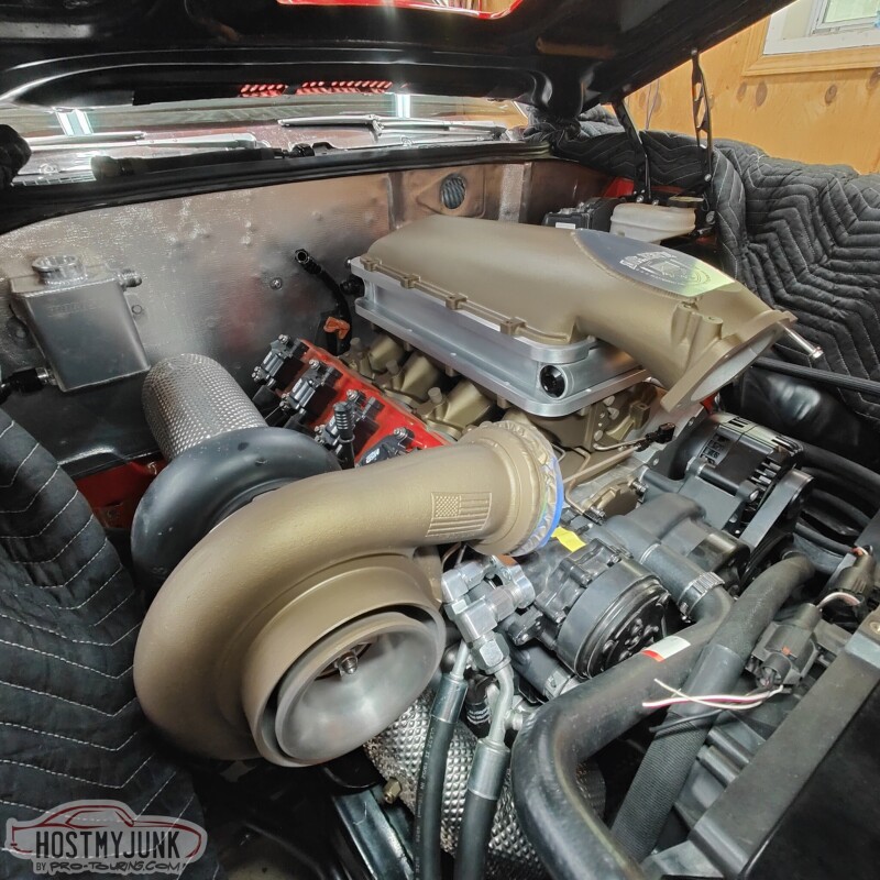
I set everything back on the engine so that the Cerakote can fully cure.
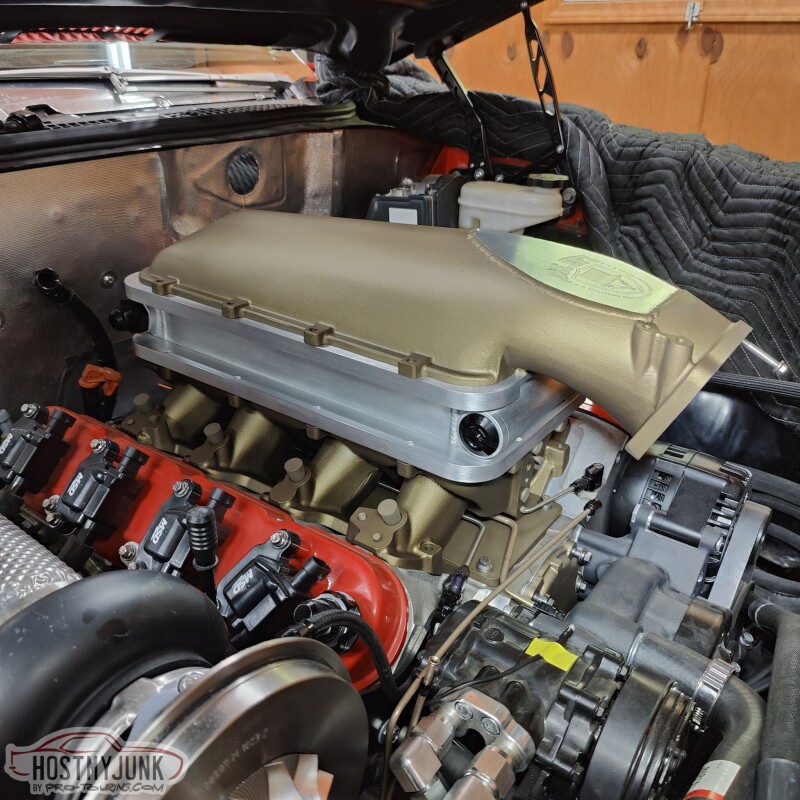
Different angle...
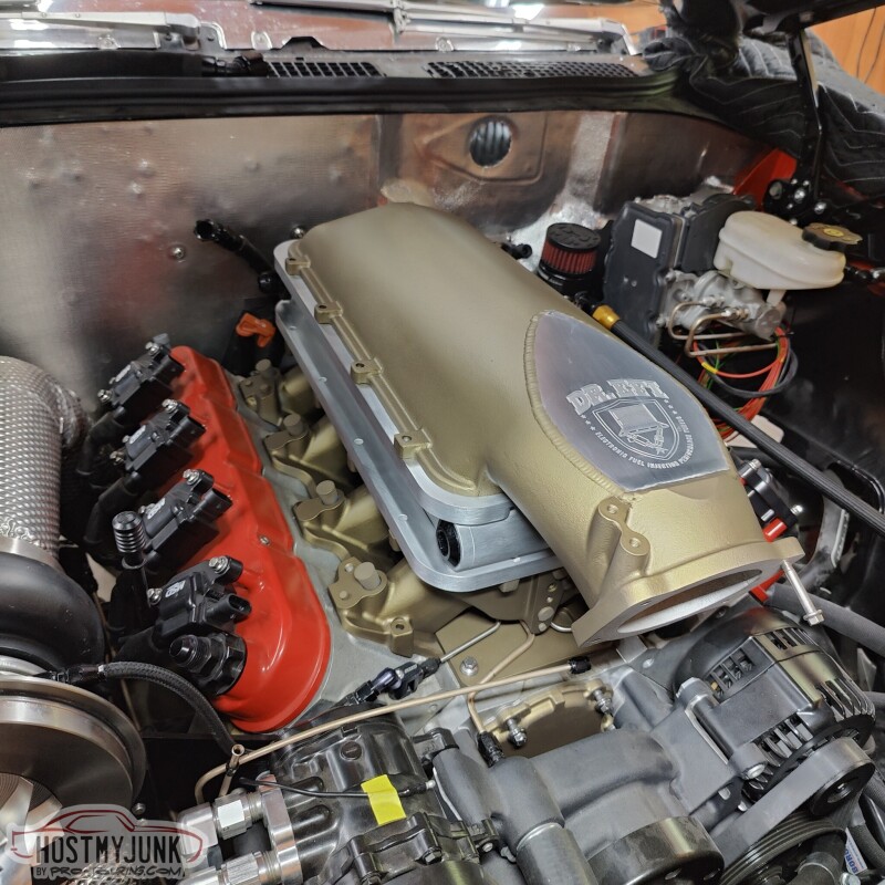
Here is a shot showing the compressor housing.
I did not mess around with the charge pipe because I want it to fully cure. Now, if I can only find all of the o-rings that I need to finally assemble everything....
Andrew
I had 4 parts to coat: compressor housing, charge pipe, intake lid and intake base (not pictured).
This guy was super helpful for cleaning. I filled it up with acetone, pressurized the can, and it sprayed a beautiful, fine mist that cleaned the parts well. Everything was already bead blasted before hand. I just sprayed everything down, used a red 3M pad to clean, and sprayed again. Then I used a MAP gas torch to heat the parts and evaporate all of the acetone.
I am using the Cerakite C coating, in the same burnt bronze color that I used on the valley cover and the front cover. You put down a light coat and immediately go over it with a heavier coat. It looks amazing in the sun, because the burnt bronze has a ton of gold and copper flakes in it.
I decided to leave the intercooler in raw aluminum, but I went over all of the surfaces with the red 3M pad to give it a brushed look.
I taped off the plate with my business logo, so it would stay natural. The engraving would lose all the detail if I was to paint it.
I set everything back on the engine so that the Cerakote can fully cure.
Different angle...
Here is a shot showing the compressor housing.
I did not mess around with the charge pipe because I want it to fully cure. Now, if I can only find all of the o-rings that I need to finally assemble everything....
Andrew

The following users liked this post:
Project GatTagO (05-14-2023)
05-24-2023 | 09:39 PM
#355
Thread Starter
Joined: Mar 2003
Posts: 10,244
Likes: 1,531
From: The City of Fountains
I have ben working with The DriveShaft Shop for about 15 years on various projects. They were the ones that made the custom axles for my RX7 when installed a Ford Cobra Mustang rear diff in it. They were also the ones that made the single CV driveshaft for my GTO back in 2013 and also the dual CV driveshaft in the Cougar.
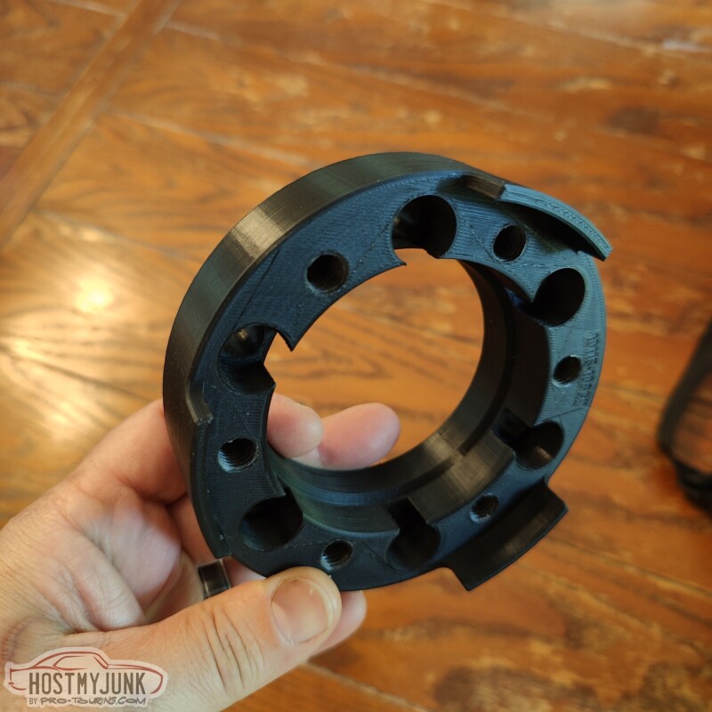
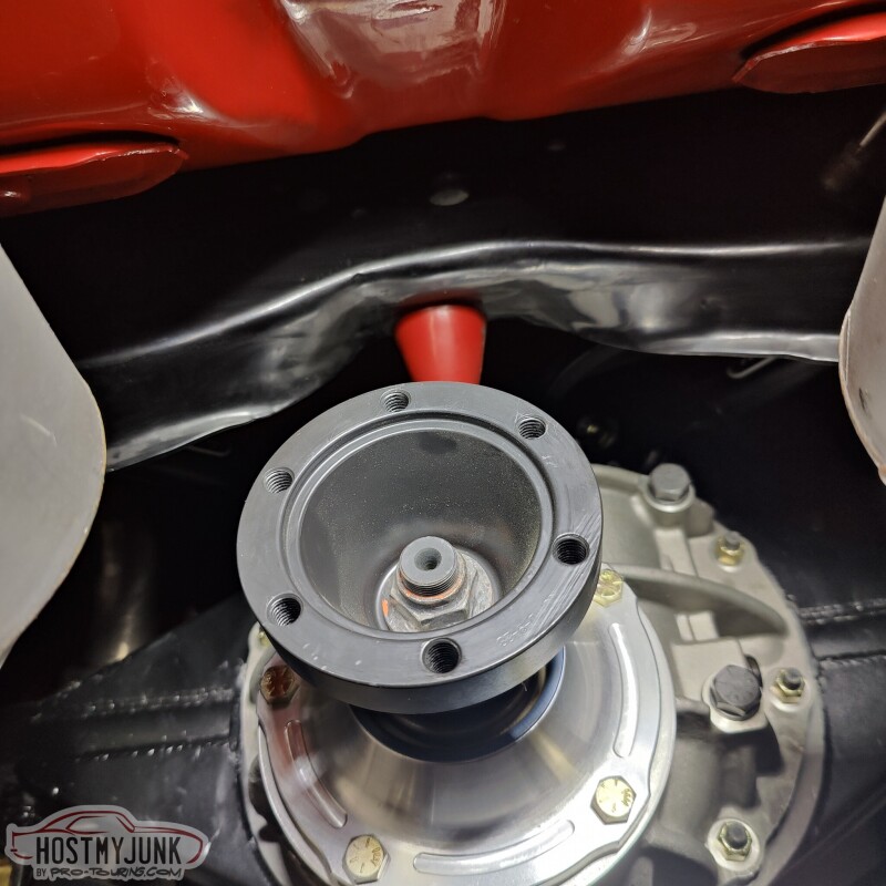
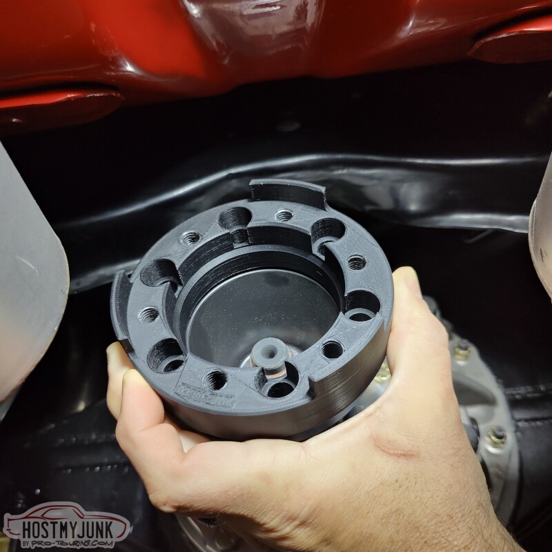
This time around they will be building a dual CV driveshaft for the GTO, but with a twist. They have some new, super strong CVs that they want to use on this project. The front slip yoke is already configured for it, but the rear needs an adapter, because the CV pinion yoke was made for the smaller CV. That said, they designed an adapter for me and sent me a 3D printed prototype for test fitting.
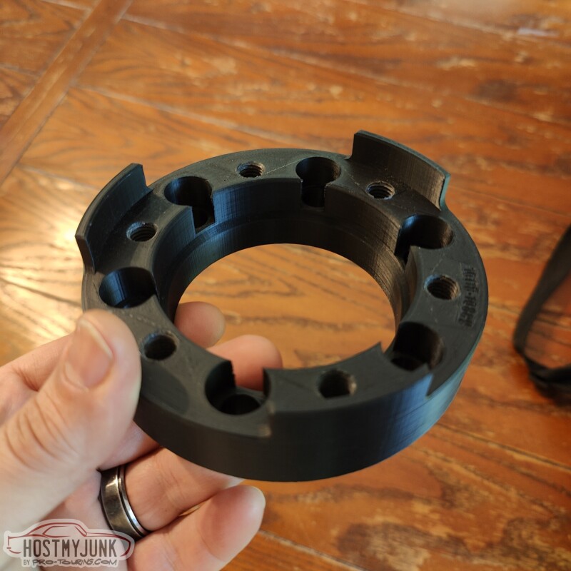
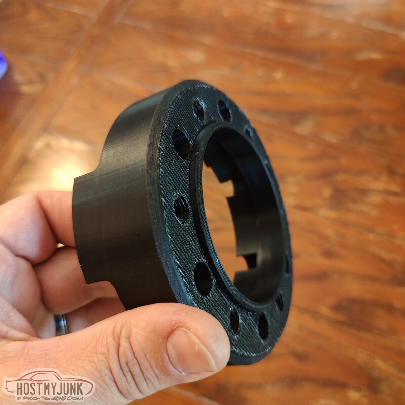
We live in truly amazing times. As Vic likes to say "That's some Buck Rogers S**t!"
Andrew
This time around they will be building a dual CV driveshaft for the GTO, but with a twist. They have some new, super strong CVs that they want to use on this project. The front slip yoke is already configured for it, but the rear needs an adapter, because the CV pinion yoke was made for the smaller CV. That said, they designed an adapter for me and sent me a 3D printed prototype for test fitting.
We live in truly amazing times. As Vic likes to say "That's some Buck Rogers S**t!"
Andrew
The following users liked this post:
C5_Pete (05-26-2023)
05-24-2023 | 11:01 PM
#356

TECH Regular

Joined: Mar 2013
Posts: 493
Likes: 34
"We live in truly amazing times. As Vic likes to say "That's some Buck Rogers S**t!""
No kidding. Not only are you able to do all that you are doing but are able to share it almost instantly with others. Thanks.
No kidding. Not only are you able to do all that you are doing but are able to share it almost instantly with others. Thanks.
The following users liked this post:
Project GatTagO (05-25-2023)
06-03-2023 | 09:53 PM
#357
Thread Starter
Joined: Mar 2003
Posts: 10,244
Likes: 1,531
From: The City of Fountains
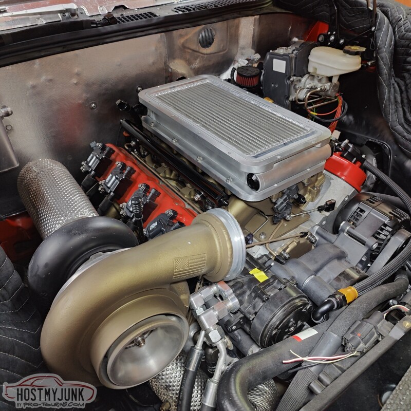
Today I had the opportunity to go work i the garage. I decided to tackle the intake manifold assembly and final installation.
The first step was to install the o-ring that seals the base with the intercooler. It is a single viton string that gets inserted into the machined groove, the ends are butted together, trimmed flush, and the a drop of super glue is used to hold it together.
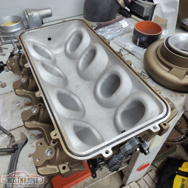
The intercooler is bolted into place.
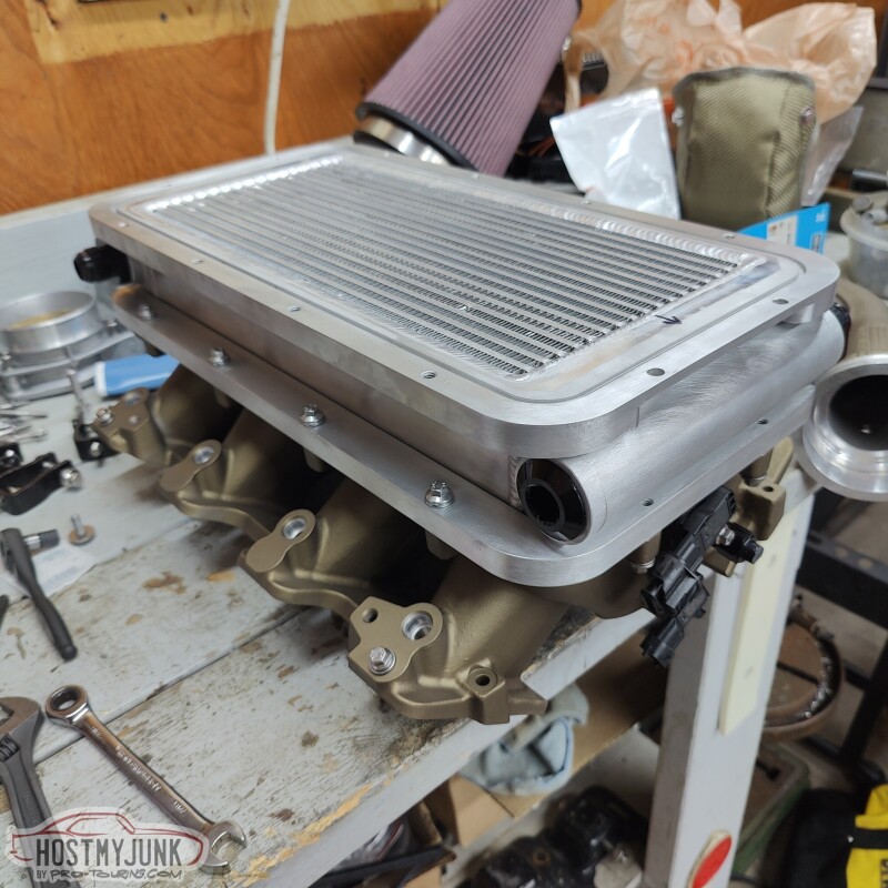
Followed by the lid.
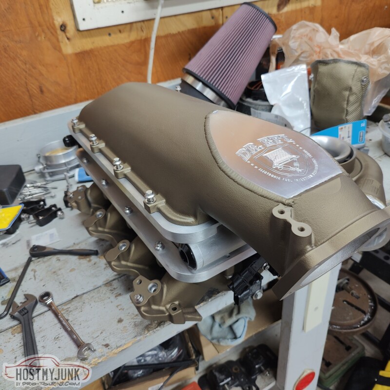
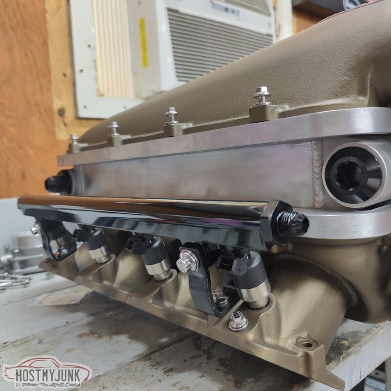
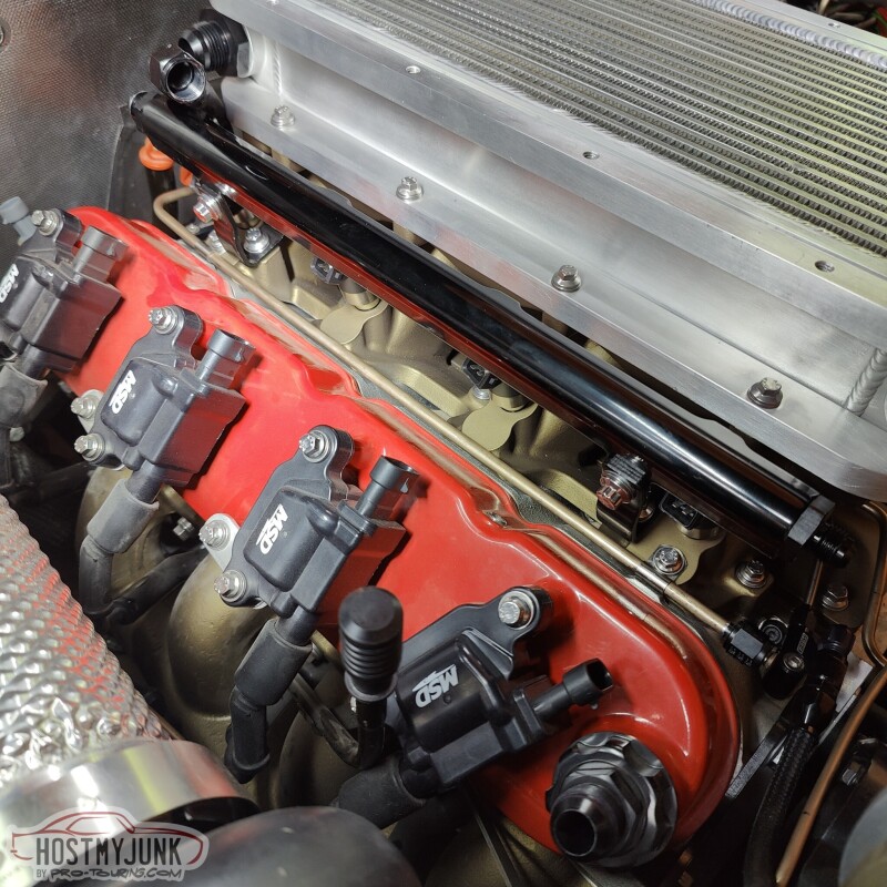
I also installed the all of the fuel injectors and rails. I used the rail brackets that came with the intake manifold, but I replaced all the hardware with ARP stainless fasters. I really like this combination of black and silver against the bronze intake manifold.
I took the masking take off the heads and cleaned everything with acetone.
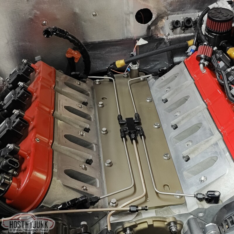
Then I installed the intake manifold assembly on the engine. The intake manifold has o-rings that seal it against the heads. I also lubricated the mating surface so the intake can easily slide around and find a happy spot as it is being torqued down.
I used these stainless p-clamps for the oil feed line, again with the ARP bolts. Vic added these holes to the intake manifold months ago.
Here is a broader view that shows all the details of the stainless hardware, with black, against the bronze intake, with a pop of red on the valve covers to keep it interesting.
Slowly, but surely...
Andrew
The first step was to install the o-ring that seals the base with the intercooler. It is a single viton string that gets inserted into the machined groove, the ends are butted together, trimmed flush, and the a drop of super glue is used to hold it together.
The intercooler is bolted into place.
Followed by the lid.
I also installed the all of the fuel injectors and rails. I used the rail brackets that came with the intake manifold, but I replaced all the hardware with ARP stainless fasters. I really like this combination of black and silver against the bronze intake manifold.
I took the masking take off the heads and cleaned everything with acetone.
Then I installed the intake manifold assembly on the engine. The intake manifold has o-rings that seal it against the heads. I also lubricated the mating surface so the intake can easily slide around and find a happy spot as it is being torqued down.
I used these stainless p-clamps for the oil feed line, again with the ARP bolts. Vic added these holes to the intake manifold months ago.
Here is a broader view that shows all the details of the stainless hardware, with black, against the bronze intake, with a pop of red on the valve covers to keep it interesting.
Slowly, but surely...
Andrew
06-27-2023 | 05:50 PM
#358
Thread Starter
Joined: Mar 2003
Posts: 10,244
Likes: 1,531
From: The City of Fountains
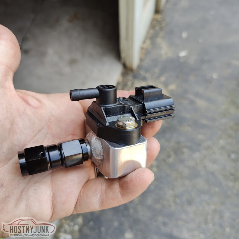
Progress has stalled a bit on the GTO, although I managed to take an interesting and useful detour. I was working with a local customer a couple of weeks ago and I noticed that his 5.4L Mustang GT500 engine had a very interesting looking sensor on the fuel rail. After some digging around I figured out that it is Bosch 0 261 230 093. What caught my eye is that one side of the sensor was in the rail while the other side had a vacuum nipple on it.
As I suspected this is a differential pressure (Delta P) sensor. It outputs the difference between rail pressure and manifold pressure (positive or negative).
You may wonder why we should care. I am glad you asked, because differential fuel pressure is actually what we really care about, not rail pressure. Another way to think of the differential pressure is the pressure across the injector discharge. Let's do an example:
Let's say you have a fuel system that is set to 60psi at the rail and there is no vacuum or boost reference on the regulator, or the regulator is not adjustable. This is a fairly common scenario with a LS swap, simple in-tank pump, and a Corvette style regulator. Let's also say that you have a moderate performance cam and the engine idle around 50kPa, which is about 15in/Hg, which is also about -7psi. Note that the units are all different, but they are describing the same thing, which is the amount of vacuum in the intake manifold when the engine is running.
In this scenario the rail pressure doesn't change, but what happens to the pressure across the injector discharge when the engine is running? Because of the vacuum that is generated by the engine, the differential pressure across the injectors is actually 67psi. In other words, the injectors act as if they flowed more. That is exactly what this sensor will read, because it measures differential pressure directly.
Consider a different scenario. Turbocharged engine, adjustable regulator with a vacuum line hooked up to it. Let's assume the same base pressure of 60psi. When the engine is running under the same conditions, a normal pressure sensor would show 53psi at the rail, but this sensor will still read true differential pressure, which in this case is 60psi. Take the same scenario under boost. Engine is making 10psi, rail pressure sensor will be reading 70psi, and this sensor will still read 60psi. The purpose of having a vacuum/boost referenced fuel system is in fact to maintain consistent differential fuel pressure.
This is a fun topic and if anyone has any questions, please post them.
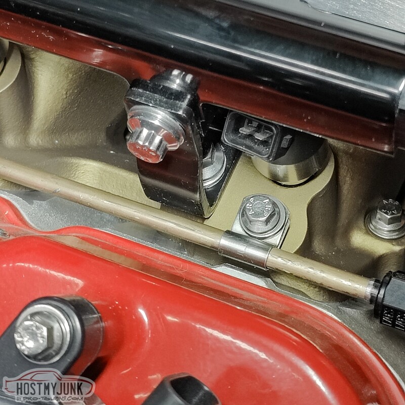
Here is sensor mount that Vic machined.
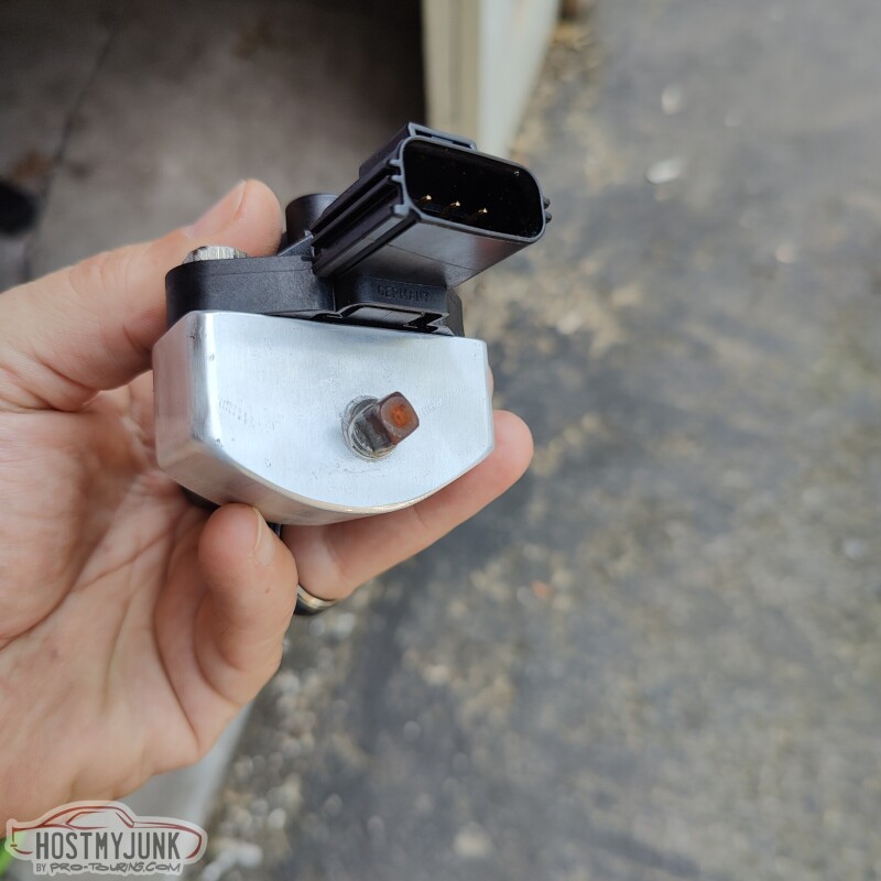
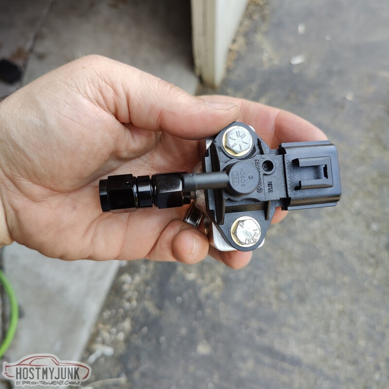
It attaches right to the back of the rail with the AN-6 female to female union.
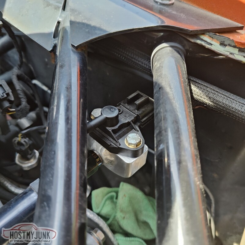
The eagle eyed will notice that it is mounted to the Cougar. I am using the Cougar to do the testing for the sensor.
Andrew
As I suspected this is a differential pressure (Delta P) sensor. It outputs the difference between rail pressure and manifold pressure (positive or negative).
You may wonder why we should care. I am glad you asked, because differential fuel pressure is actually what we really care about, not rail pressure. Another way to think of the differential pressure is the pressure across the injector discharge. Let's do an example:
Let's say you have a fuel system that is set to 60psi at the rail and there is no vacuum or boost reference on the regulator, or the regulator is not adjustable. This is a fairly common scenario with a LS swap, simple in-tank pump, and a Corvette style regulator. Let's also say that you have a moderate performance cam and the engine idle around 50kPa, which is about 15in/Hg, which is also about -7psi. Note that the units are all different, but they are describing the same thing, which is the amount of vacuum in the intake manifold when the engine is running.
In this scenario the rail pressure doesn't change, but what happens to the pressure across the injector discharge when the engine is running? Because of the vacuum that is generated by the engine, the differential pressure across the injectors is actually 67psi. In other words, the injectors act as if they flowed more. That is exactly what this sensor will read, because it measures differential pressure directly.
Consider a different scenario. Turbocharged engine, adjustable regulator with a vacuum line hooked up to it. Let's assume the same base pressure of 60psi. When the engine is running under the same conditions, a normal pressure sensor would show 53psi at the rail, but this sensor will still read true differential pressure, which in this case is 60psi. Take the same scenario under boost. Engine is making 10psi, rail pressure sensor will be reading 70psi, and this sensor will still read 60psi. The purpose of having a vacuum/boost referenced fuel system is in fact to maintain consistent differential fuel pressure.
This is a fun topic and if anyone has any questions, please post them.
Here is sensor mount that Vic machined.
It attaches right to the back of the rail with the AN-6 female to female union.
The eagle eyed will notice that it is mounted to the Cougar. I am using the Cougar to do the testing for the sensor.
Andrew
The following 2 users liked this post by Project GatTagO:
Full Power (11-17-2023), The BallSS (06-28-2023)
 07-20-2023 | 10:22 PM
#360
Thread Starter
Joined: Mar 2003
Posts: 10,244
Likes: 1,531
From: The City of Fountains
Progress on the GTO is a little slow, but moving along. I need to thank my friends at The DriveShaft Shop for making me a bullet proof, dual CV, carbon fiber driveshaft.
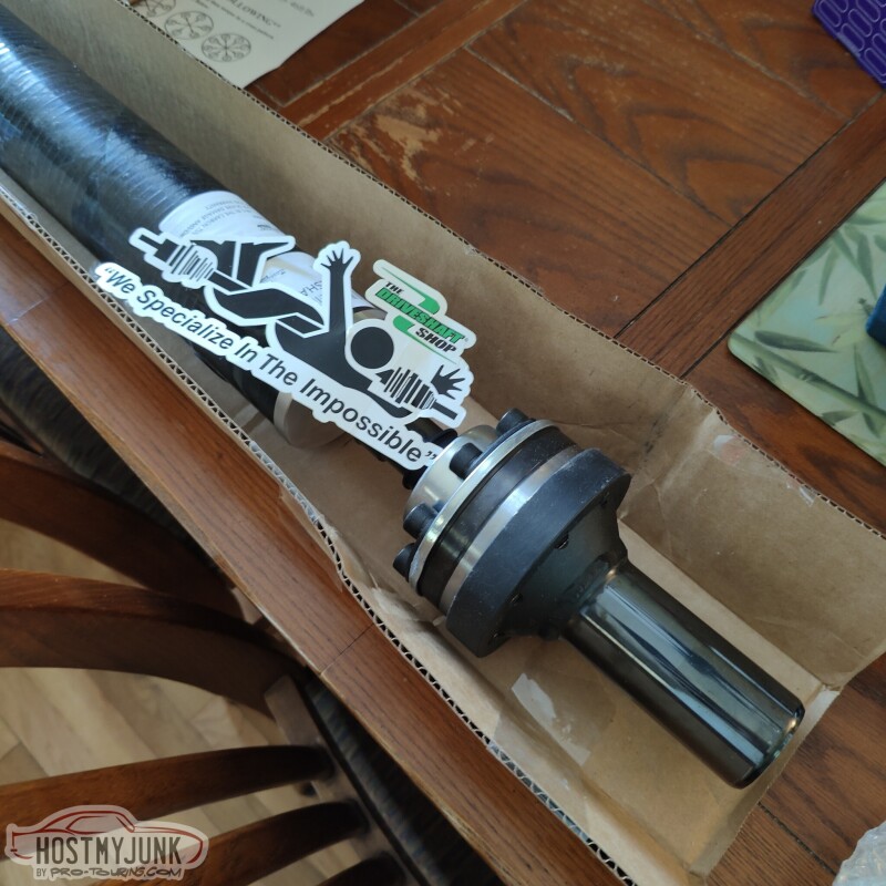
Here you can see the details of the 108mm non plunging CV and the carbon fiber tube.
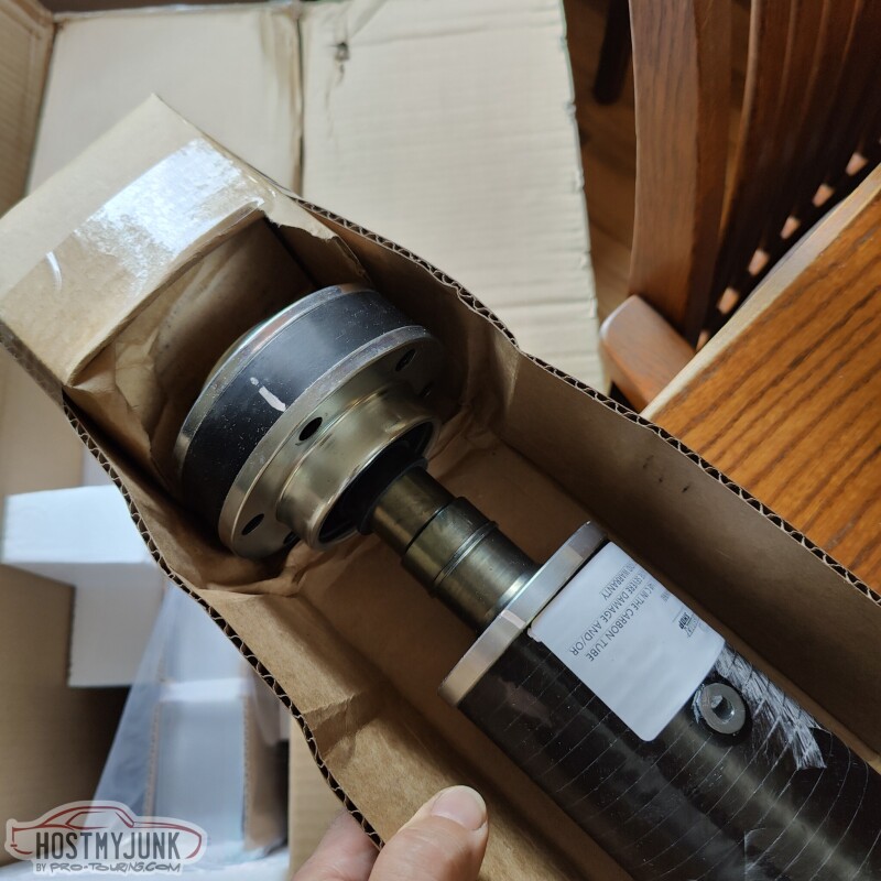
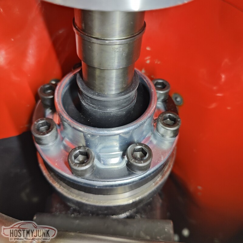
This is their new design 8 bolt non-plunging CV. These are used on the Nissan GTR 2500+hp driveshafts. Good enough for this pile...
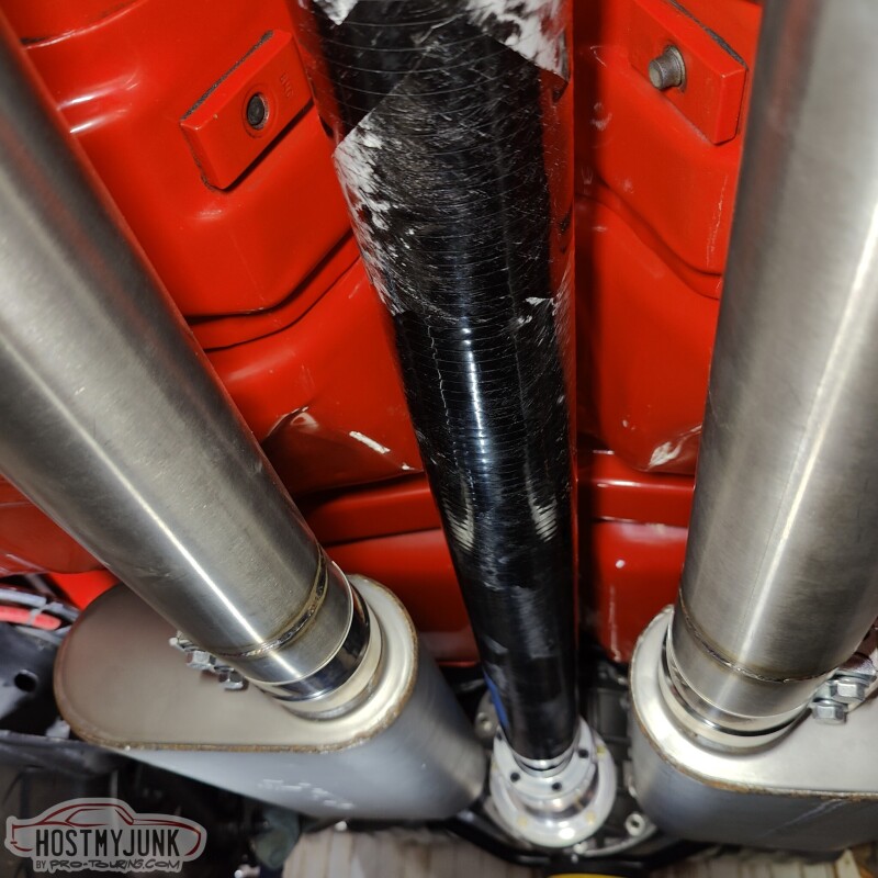
Here you can see how it fits between the exhaust. There is plenty of clearance, so heat should not be a concern. Besides, there is a constant stream of air passing under the car while it is moving, which cools the exhaust.
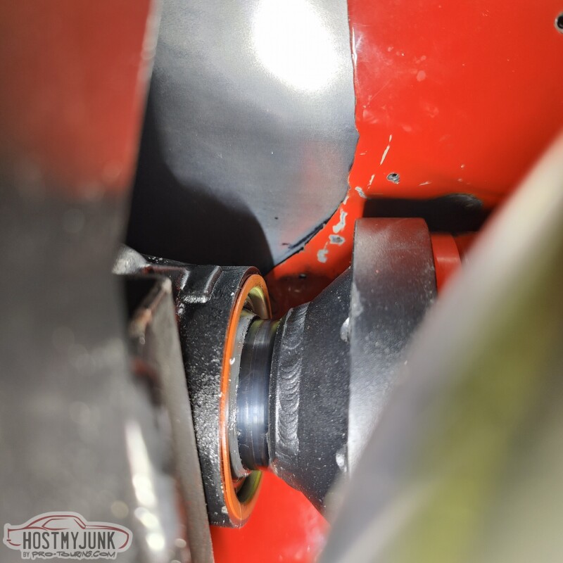
Plenty of stick-out for any little movement from the rear end articulation and deflection.
Andrew
Here you can see the details of the 108mm non plunging CV and the carbon fiber tube.
This is their new design 8 bolt non-plunging CV. These are used on the Nissan GTR 2500+hp driveshafts. Good enough for this pile...
Here you can see how it fits between the exhaust. There is plenty of clearance, so heat should not be a concern. Besides, there is a constant stream of air passing under the car while it is moving, which cools the exhaust.
Plenty of stick-out for any little movement from the rear end articulation and deflection.
Andrew
The following users liked this post:
C5_Pete (07-30-2023)