
First turbo build, 70 GTO...
 02-27-2022 | 05:00 PM
#101
Thread Starter

Joined: Mar 2003
Posts: 10,244
Likes: 1,533
From: The City of Fountains
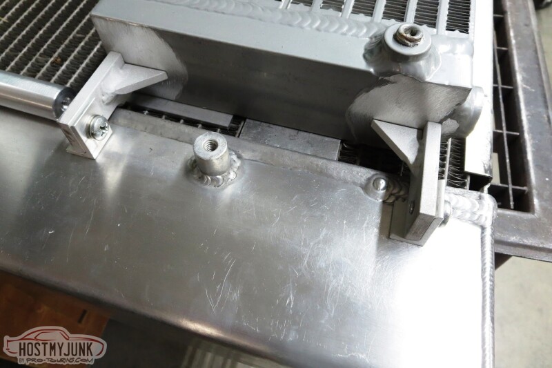
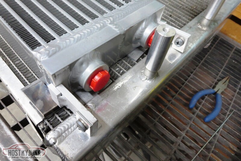
Vic has been making progress on getting the heat exchanger, fans, and condenser mounted to the radiator.
I also mocked up the CWA150 pump against the fan shroud and it looks like it will fit nicely in the location where the Volt used to have a similar pump.
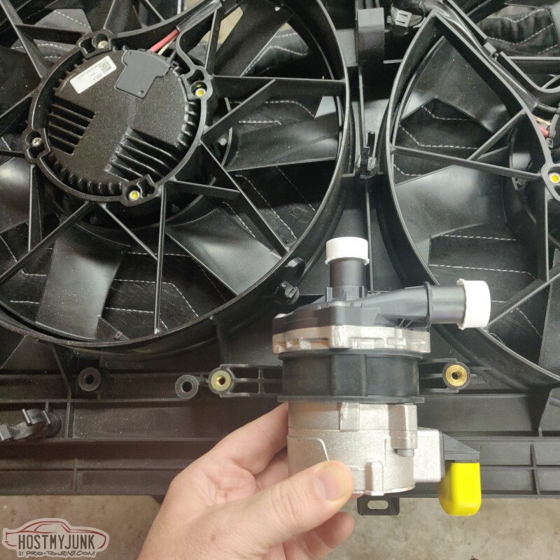
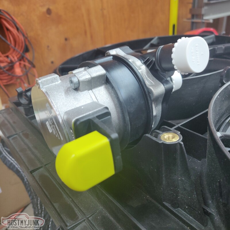
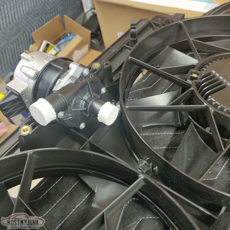
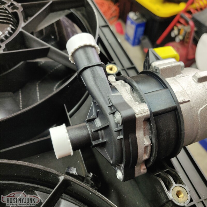
The CWA150 pump is a little smaller in diameter than the cradle, but I think a little 3D printed cradle will make up the difference nicely and will allow me to offset the pump off to the side a little.
Andrew
I also mocked up the CWA150 pump against the fan shroud and it looks like it will fit nicely in the location where the Volt used to have a similar pump.
The CWA150 pump is a little smaller in diameter than the cradle, but I think a little 3D printed cradle will make up the difference nicely and will allow me to offset the pump off to the side a little.
Andrew
The following users liked this post:
spray280 (03-01-2022)
The following users liked this post:
Project GatTagO (02-27-2022)
03-01-2022 | 08:59 AM
#103
Thread Starter
Joined: Mar 2003
Posts: 10,244
Likes: 1,533
From: The City of Fountains
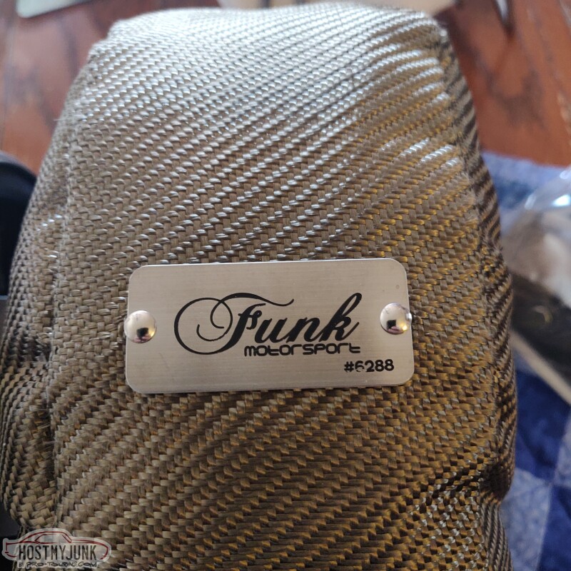
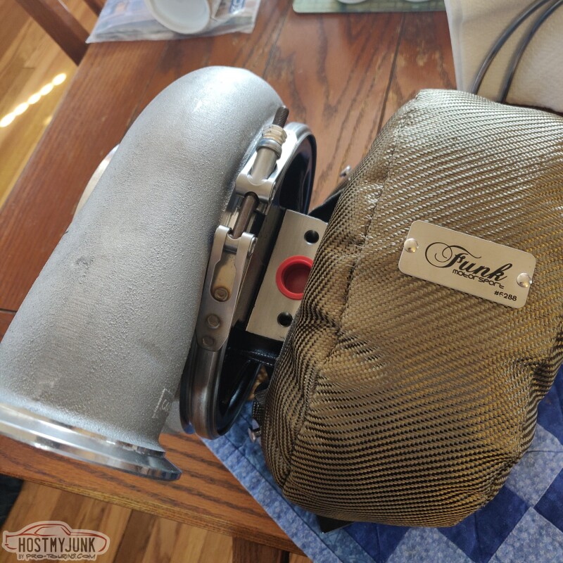
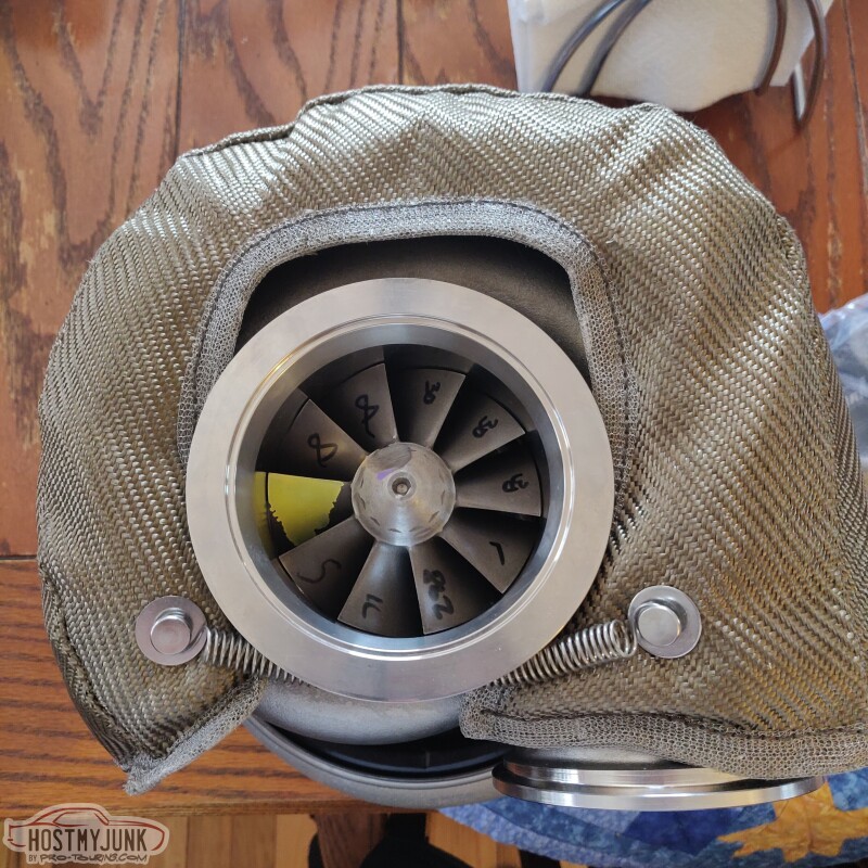
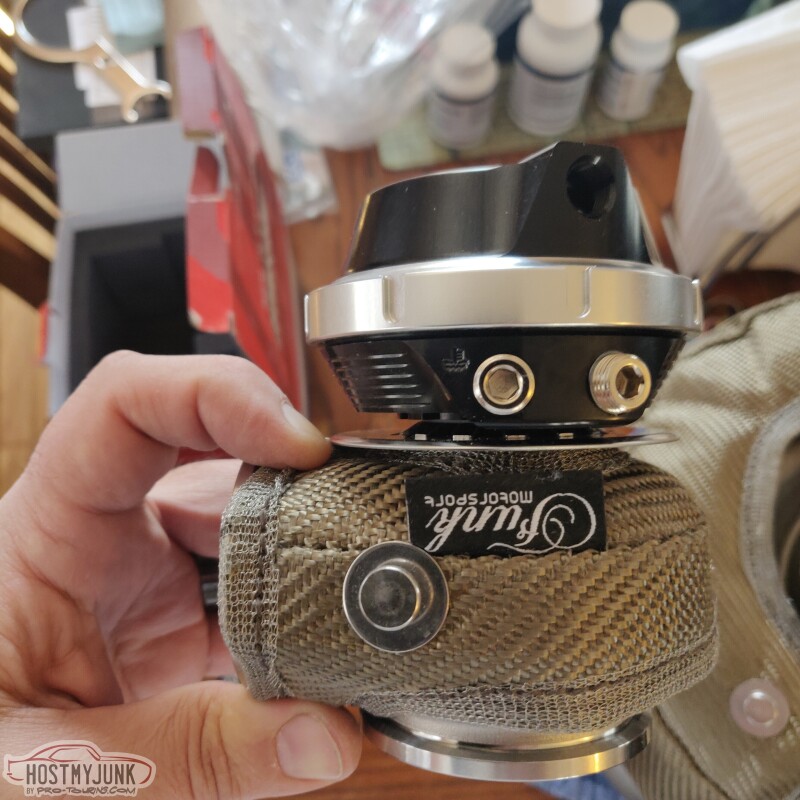
To keep engine bay temperatures down and to help the turbo retain heat, I got these turbo and waste gate blankets from Funk Motorsports in the UK. They look great and fit very well.
Andrew
Andrew
The following users liked this post:
spray280 (03-01-2022)
03-01-2022 | 10:12 PM
#104
Thread Starter
Joined: Mar 2003
Posts: 10,244
Likes: 1,533
From: The City of Fountains
Today was almost 70 degrees and I couldn't let this day pass by. This project isn't going to get done by itself. So I went to Harbor Freight and got a new air compressor after realizing that my old one has seized up. Got a new hose, some fittings, and a few odds and ends and went work. I asked if they had "bailing wire" and the girl looked at me like I was crazy. Then I described what it was and she said, we have this...Apparently now days bailing wire is called "mechanics wire" and it is stainless. Who knew...:hand:
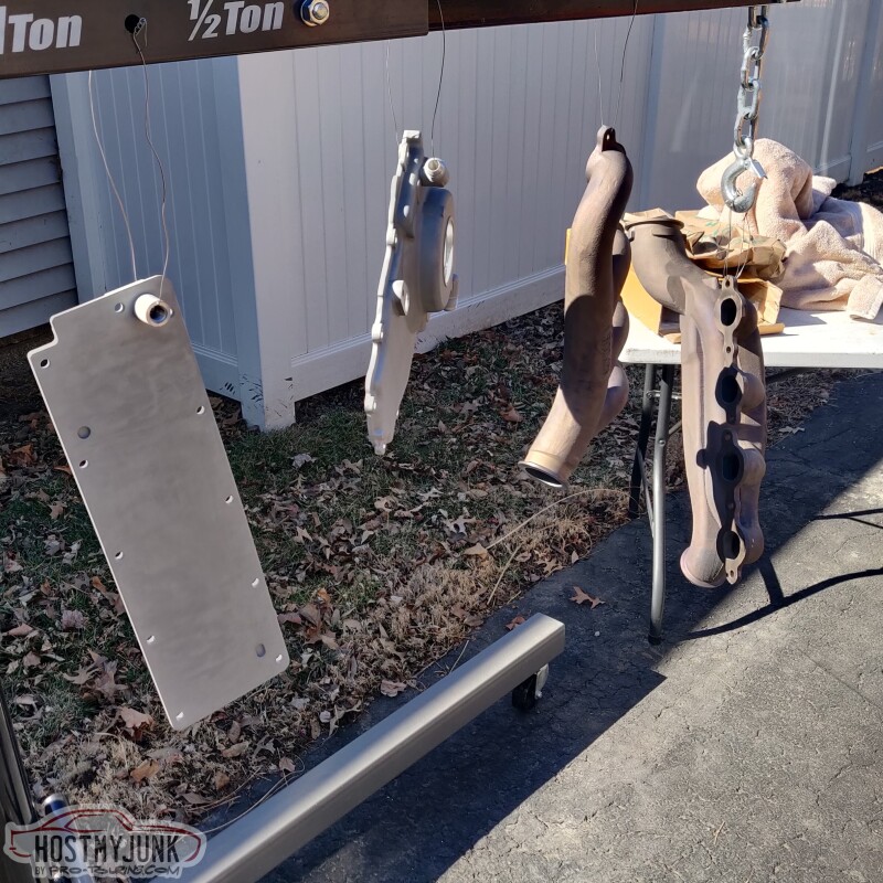
The in between pictures didn't turn out so good because of the bright sunshine, but here are the pictures after 6 hours when I brought them into the house.
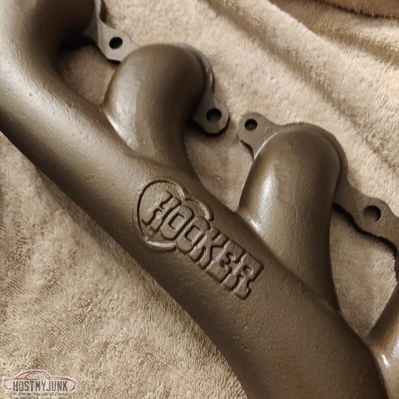
I am really happy with how everything turned out. Like, really happy!
Andrew
The in between pictures didn't turn out so good because of the bright sunshine, but here are the pictures after 6 hours when I brought them into the house.
I am really happy with how everything turned out. Like, really happy!
Andrew
03-02-2022 | 05:56 AM
#105

Didn't realize they had a wastegate blanket. I have used the Eastwood header paint, seems to last pretty good.
I wrap the manifolds anyway, but might take them this time to where they "cook" the header coating.
You are def. going to have a detailed build, should look killer.
I wrap the manifolds anyway, but might take them this time to where they "cook" the header coating.
You are def. going to have a detailed build, should look killer.
The following users liked this post:
Project GatTagO (03-02-2022)
03-02-2022 | 02:06 PM
#106
Thread Starter
Joined: Mar 2003
Posts: 10,244
Likes: 1,533
From: The City of Fountains
Didn't realize they had a wastegate blanket. I have used the Eastwood header paint, seems to last pretty good.
I wrap the manifolds anyway, but might take them this time to where they "cook" the header coating.
You are def. going to have a detailed build, should look killer.
I wrap the manifolds anyway, but might take them this time to where they "cook" the header coating.
You are def. going to have a detailed build, should look killer.
Andrew
03-02-2022 | 09:18 PM
#107
Thread Starter
Joined: Mar 2003
Posts: 10,244
Likes: 1,533
From: The City of Fountains
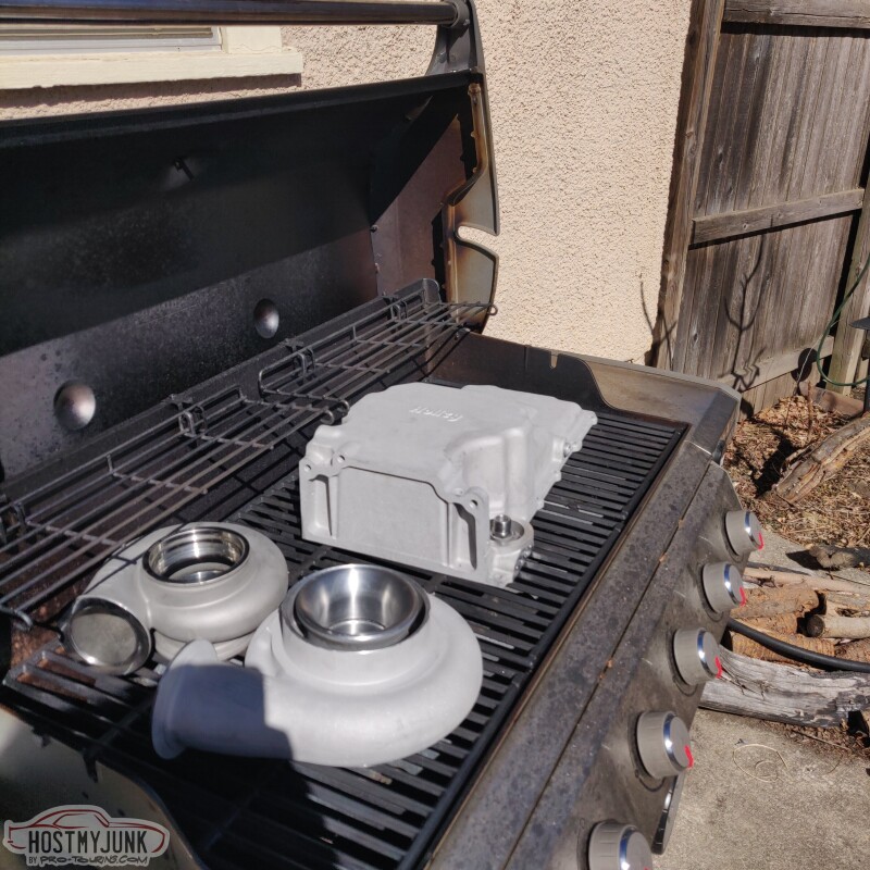
I couldn't let this string of warm days go to waste, so this morning I went to Vic's house again. He was once again kind enough to let me use his blast cabinet to prep the oil pan, turbine housing, and the compressor cover.
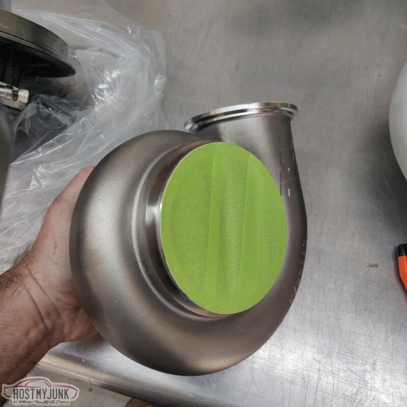
Both the turbine housing and the compressor cover have machined surfaces that needed to be masked off. Here is the exhaust housing before blasting.
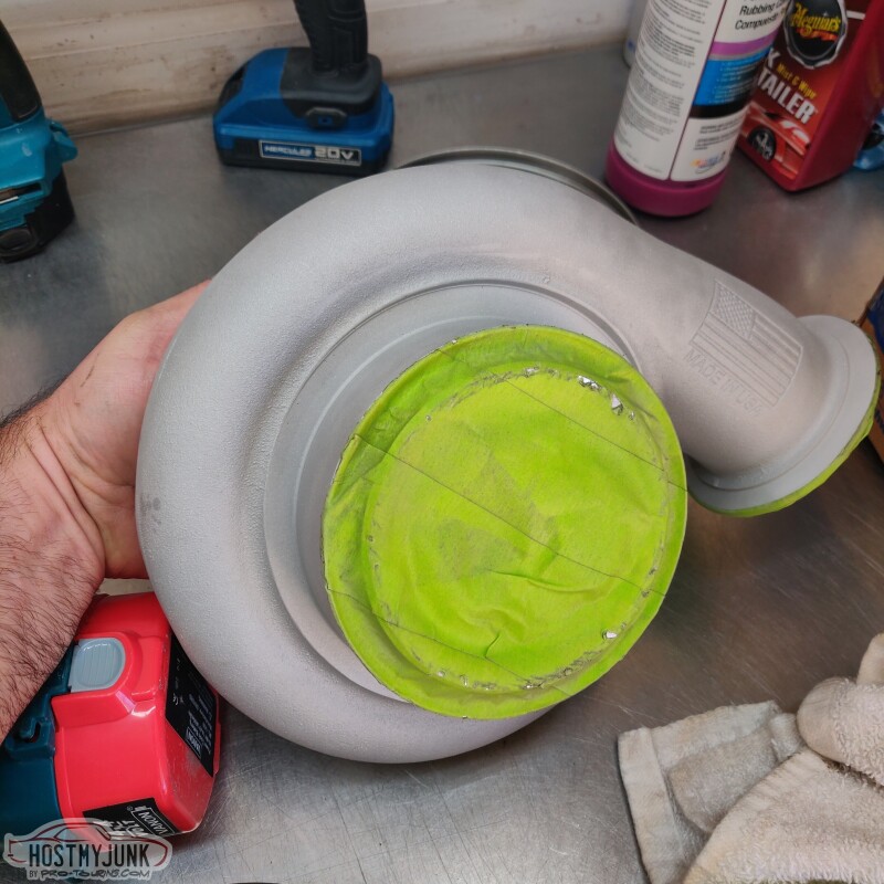
This is the compressor housing after blasting. I also blasted the oil pan and then washed it in his solvent tank.
Then into the Weber they went for an hour at 500 degrees.
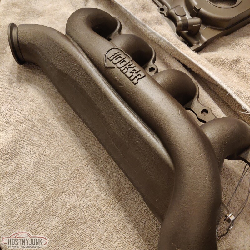
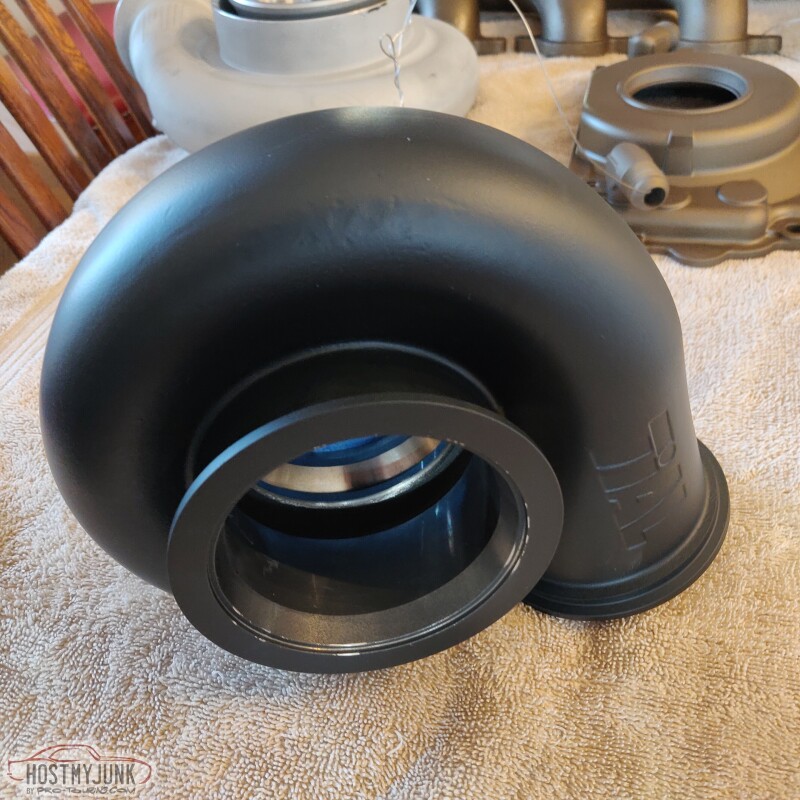
When I ordered the sample pack from Cerakote, I got burnt bronze, glacier black and glacier titanium. So I wanted to try those colors. I chose glacier black for the turbine housing. Here is it right after I sprayed it.
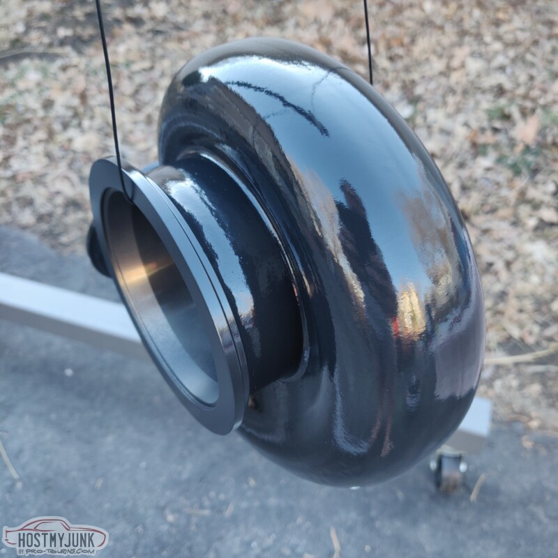
After having some time to dry, it is settling into a very nice, rich black with an eggshell sheen.
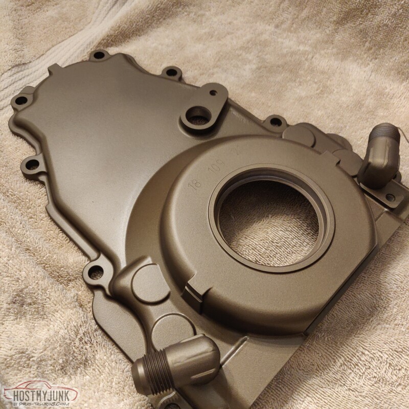
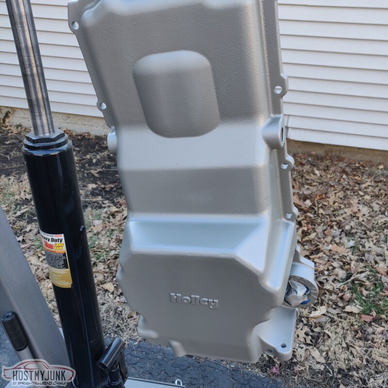
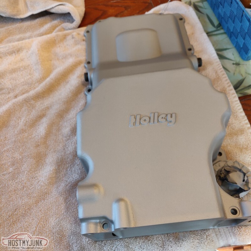
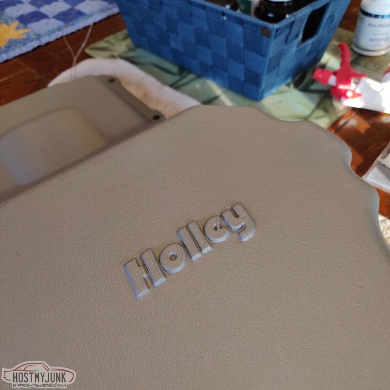
This is the glacier titanium. It is a little boring and I don't think I would use it on anything else. The main reason for doing the pan was so that it wouldn't instantly get dirty as base aluminum castings tend to do.
I have more burnt bronze and glacier black on order. The compressor housing will be burnt bronze as will the lower and upper parts of the Holley intake manifold. The Tick intercooler in between the upper and lower will be glacier black.
Andrew
Both the turbine housing and the compressor cover have machined surfaces that needed to be masked off. Here is the exhaust housing before blasting.
This is the compressor housing after blasting. I also blasted the oil pan and then washed it in his solvent tank.
Then into the Weber they went for an hour at 500 degrees.
When I ordered the sample pack from Cerakote, I got burnt bronze, glacier black and glacier titanium. So I wanted to try those colors. I chose glacier black for the turbine housing. Here is it right after I sprayed it.
After having some time to dry, it is settling into a very nice, rich black with an eggshell sheen.
This is the glacier titanium. It is a little boring and I don't think I would use it on anything else. The main reason for doing the pan was so that it wouldn't instantly get dirty as base aluminum castings tend to do.
I have more burnt bronze and glacier black on order. The compressor housing will be burnt bronze as will the lower and upper parts of the Holley intake manifold. The Tick intercooler in between the upper and lower will be glacier black.
Andrew
The following users liked this post:
forcd ind (03-03-2022)
03-03-2022 | 05:42 AM
#108

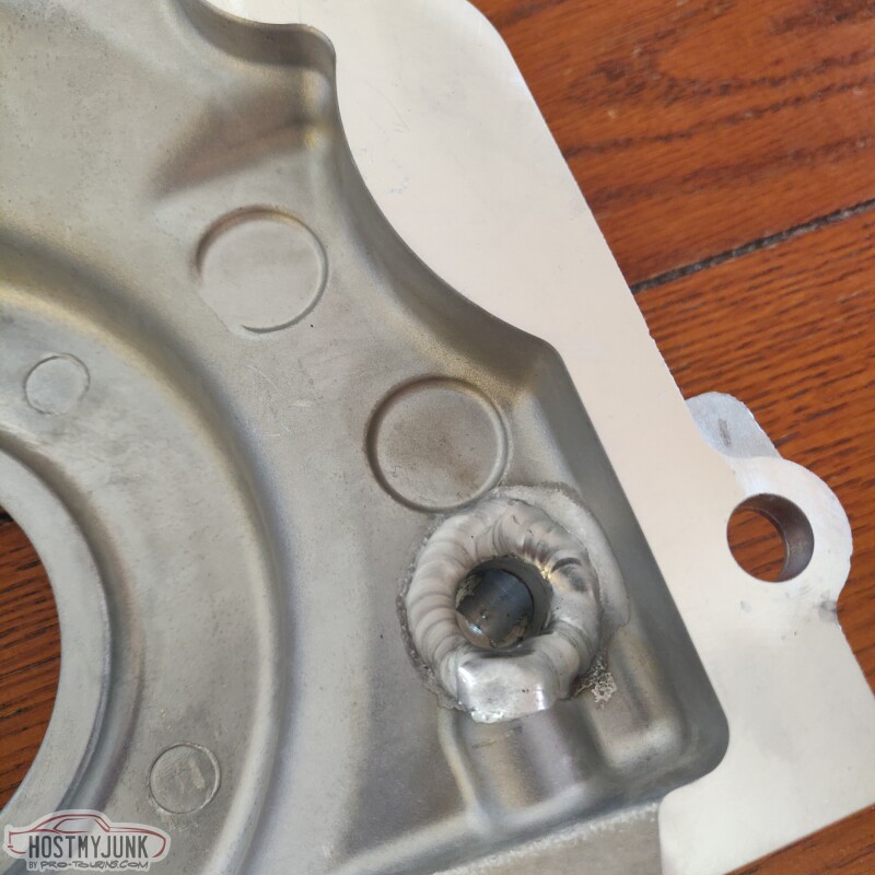
I've been using this same Timing cover for both my Twin GT35's and my current VSRS480 (One is capped off) and it works great. The only caveat is that, unlike the stock cover, there isn't any water pump bolt head reliefs in it (I'm using the F-body water pump though , so it may not matter for other water pumps). I had to take a grinder and grind the bolt heads on the back of my water pump flat in order to let the water pump seat when I assembled the WP on the engine.
The following 2 users liked this post by mightyquickz28:
Project GatTagO (03-03-2022), ryeguy2006a (03-04-2022)
03-04-2022 | 03:30 PM
#109
Thread Starter
Joined: Mar 2003
Posts: 10,244
Likes: 1,533
From: The City of Fountains
Here is the turbine housing after it had dried overnight. I really like the sheen. This is the Glacier Black.
This is the glacier titanium after it has dried. It basically looks like cast aluminum
Today I also received the Circle D converter. It is the triple disk, billet converter.
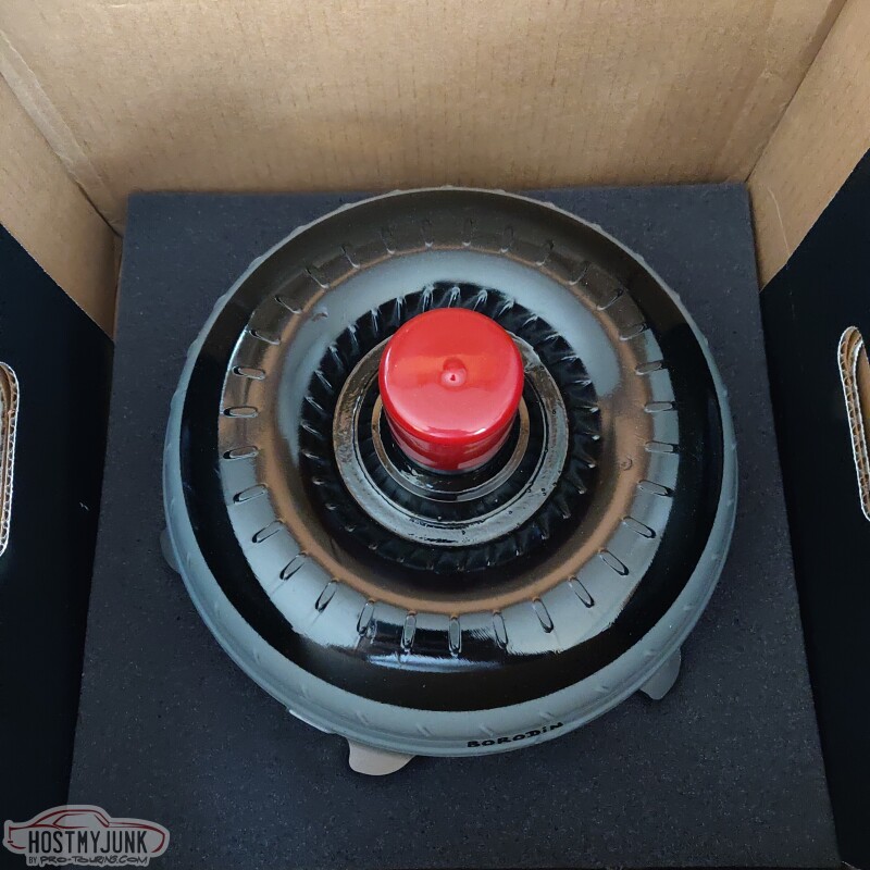
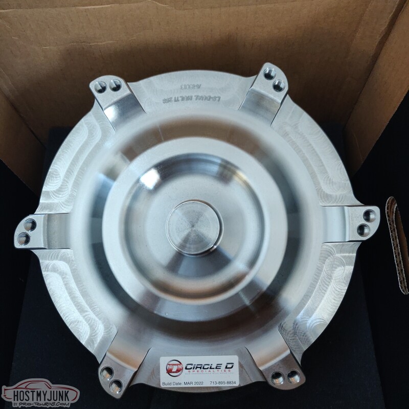
I also got their billet steel flex plate, just to make sure.
Andrew
This is the glacier titanium after it has dried. It basically looks like cast aluminum
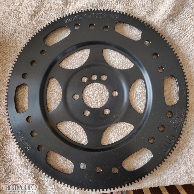
Today I also received the Circle D converter. It is the triple disk, billet converter.
I also got their billet steel flex plate, just to make sure.
Andrew
03-08-2022 | 10:55 PM
#110
Thread Starter
Joined: Mar 2003
Posts: 10,244
Likes: 1,533
From: The City of Fountains
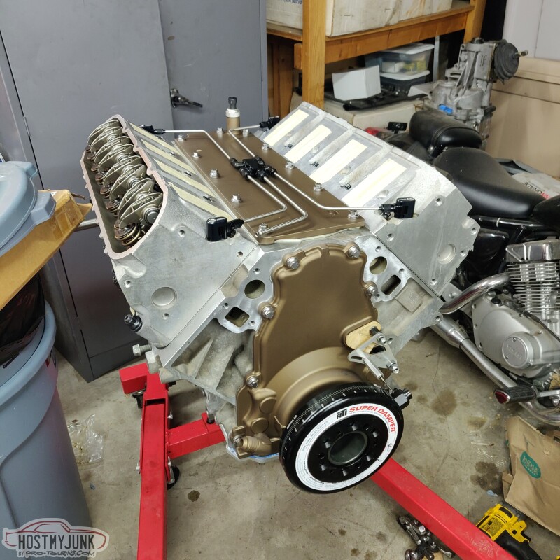
Despite the weather being a little chilly today, I decided to go out to the garage and make some progress on the engine. Besides, my wife is tired of all the car parts banging around the house.
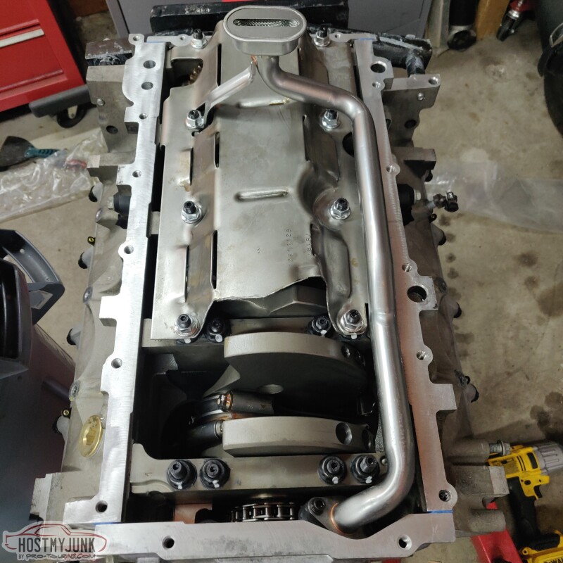
I needed to get the bottom of the block buttoned up, so the first order of business was to get the windage tray and the oil pick-up installed. Since this engine now had ARP main studs, I had to open up a couple of oval shaped holes on the windage tray. A step drill made really fast work of it.
The ARP main stud kit came with new nuts for the windage tray.
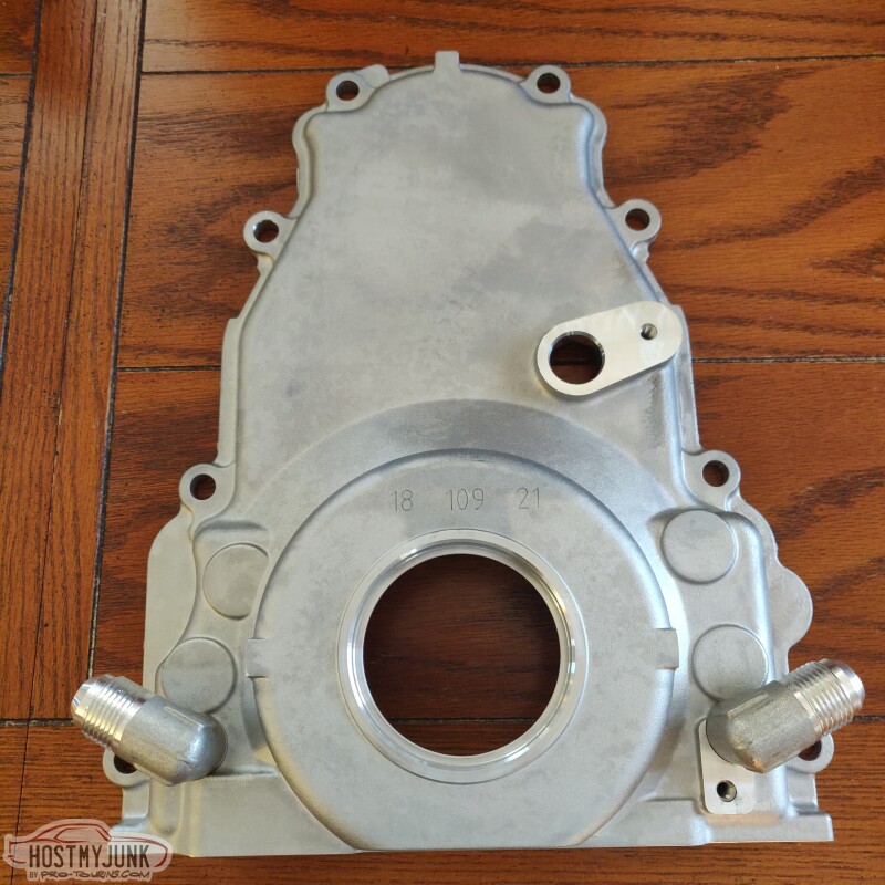
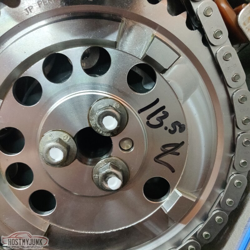
Took the old front cover off and saw marks from when the engine builder degreed the cam.
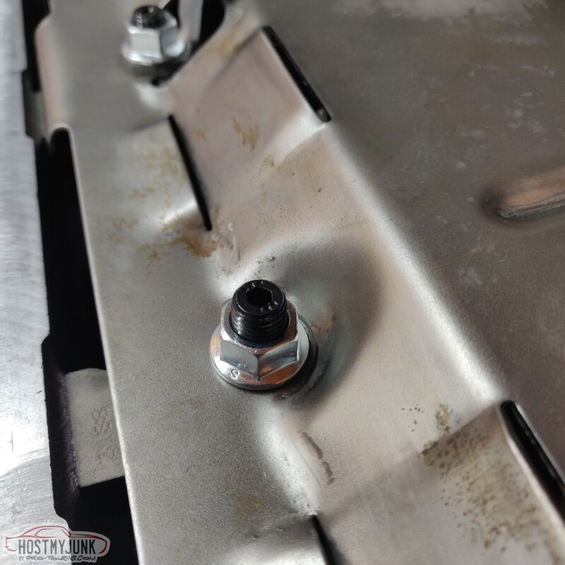
I started to install the oil pan, and the very first bolt was cross threading...Had to make a trip to Napa for a tap, but thankfully I managed to fix it.
Installed a new crank seal.
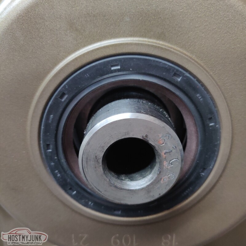
Then I took a break and baked the balancer hub in the oven for an hour, and just like last time, it slid right on.
Then the pan was installed, hopefully for the last time!
More to come...
I needed to get the bottom of the block buttoned up, so the first order of business was to get the windage tray and the oil pick-up installed. Since this engine now had ARP main studs, I had to open up a couple of oval shaped holes on the windage tray. A step drill made really fast work of it.
The ARP main stud kit came with new nuts for the windage tray.
Took the old front cover off and saw marks from when the engine builder degreed the cam.
I started to install the oil pan, and the very first bolt was cross threading...Had to make a trip to Napa for a tap, but thankfully I managed to fix it.
Installed a new crank seal.
Then I took a break and baked the balancer hub in the oven for an hour, and just like last time, it slid right on.
Then the pan was installed, hopefully for the last time!
More to come...
03-08-2022 | 10:55 PM
#111
Thread Starter
Joined: Mar 2003
Posts: 10,244
Likes: 1,533
From: The City of Fountains
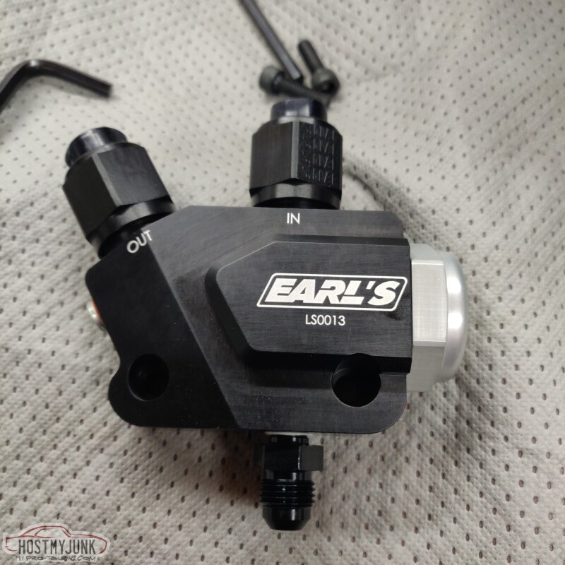
I knew that I needed to plumb oil to the turbo, so I chose this adapter from Earl's. This one is also set-up for an oil cooler and has a build in thermostat. I haven't decided if I am going to use an oil cooler, but I will be using the bottom port for turbo oil feed.
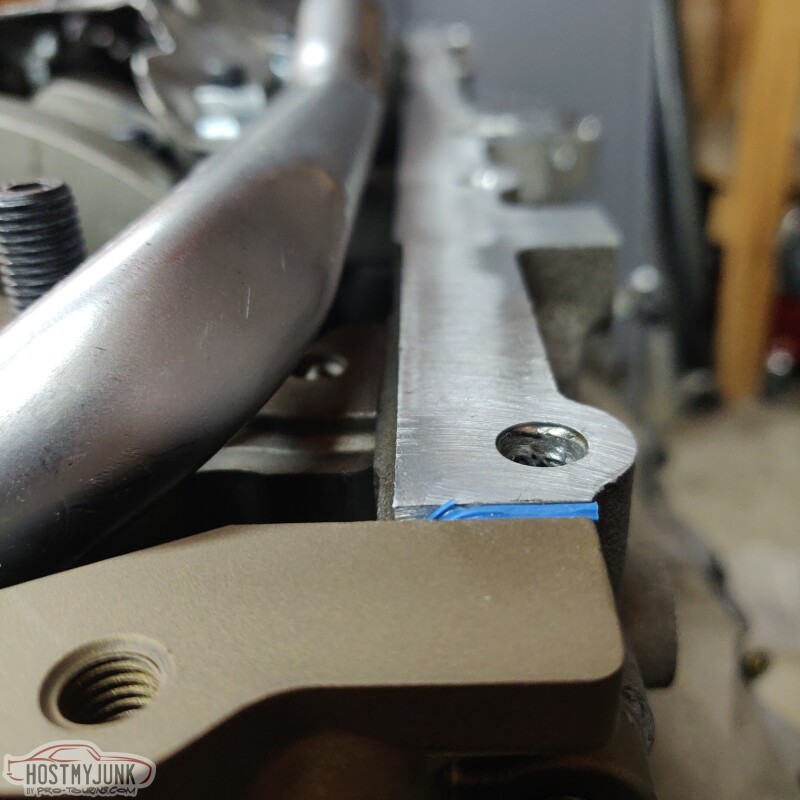
There is a lot of debate as to whether having rear steam ports help in boosted applications. I decided that it can't hurt, so I drilled out the little rivets that were installed in the rear of the heads.
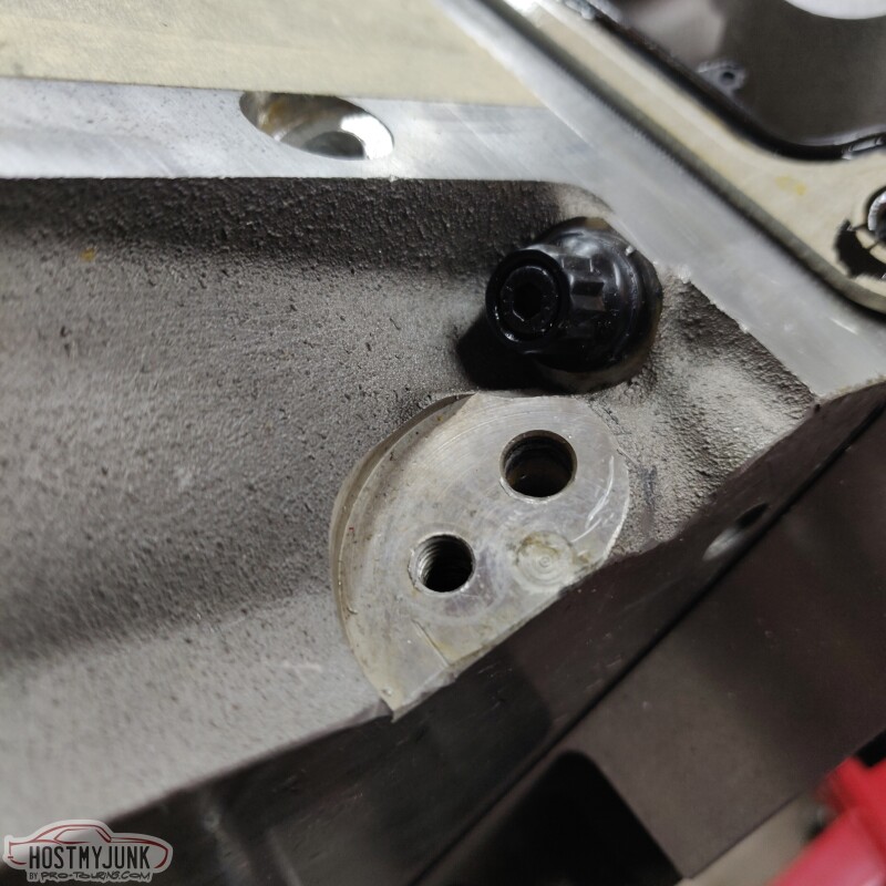
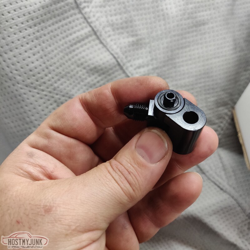
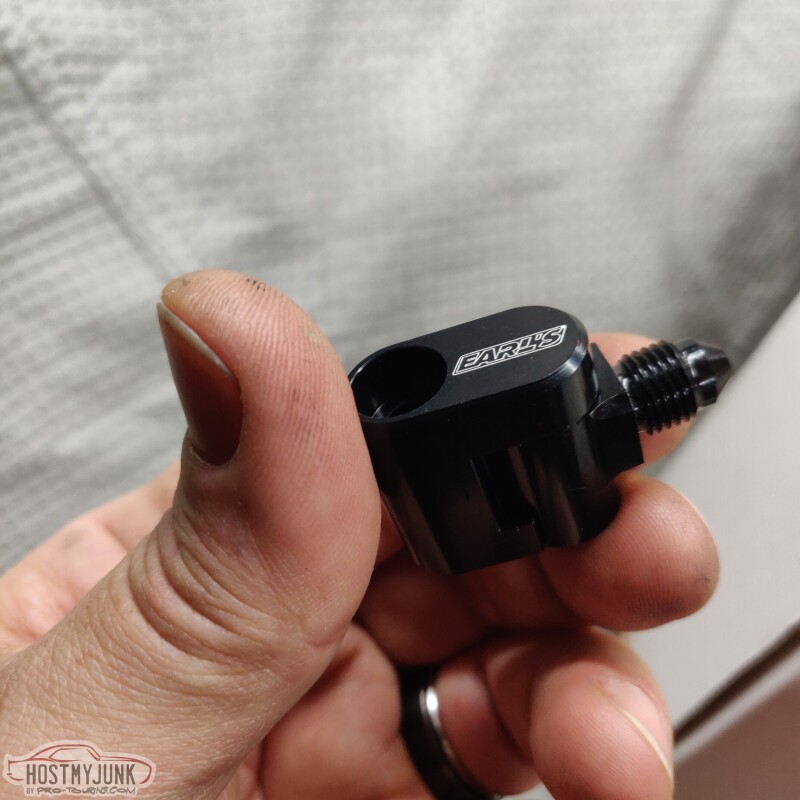
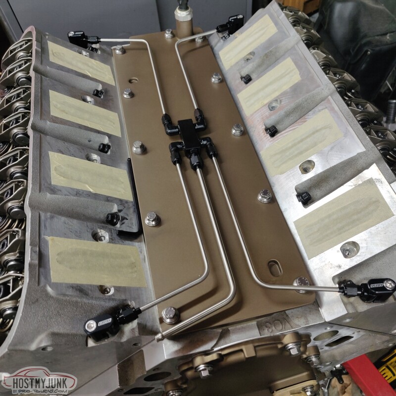
These are the steam vent adapters that are part of the Earl's 4 port steam vent kit. I really like this design because they use o-rings and they swivel.
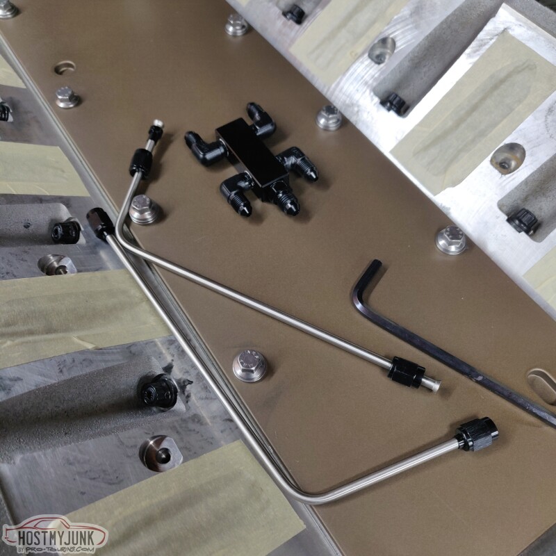
The kit included an assembled central manifold and 5 pre-bent lines.
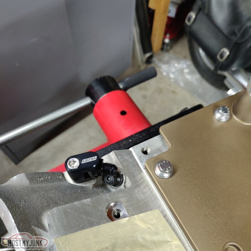
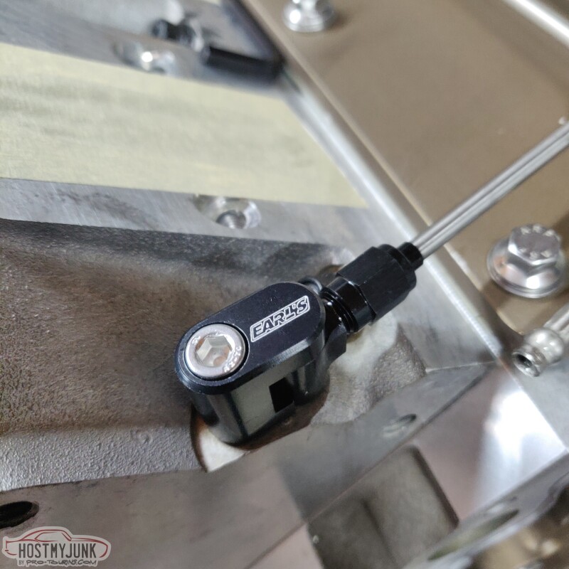
Here is the adapter installed in the rear of the head. The picture makes it look like they are hitting one of the head studs, but it's not even close.
More to come...
There is a lot of debate as to whether having rear steam ports help in boosted applications. I decided that it can't hurt, so I drilled out the little rivets that were installed in the rear of the heads.
These are the steam vent adapters that are part of the Earl's 4 port steam vent kit. I really like this design because they use o-rings and they swivel.
The kit included an assembled central manifold and 5 pre-bent lines.
Here is the adapter installed in the rear of the head. The picture makes it look like they are hitting one of the head studs, but it's not even close.
More to come...
03-08-2022 | 10:57 PM
#112
Thread Starter
Joined: Mar 2003
Posts: 10,244
Likes: 1,533
From: The City of Fountains
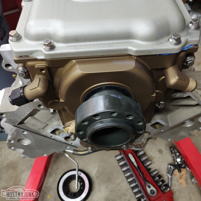
This is the whole kit, fully assembled. The center tube is the outlet and will be plumbed to an existing hole on the mid-mount water pump casting. I don't particularly like the way that the steam manifold just sort of hangs in mid air. I am contemplating mounting it somehow to the valley cover so it has some support.
I love the little details, like the laser etched Earl's logo.
Since this is a turbo build, I felt like having the ability to confirm ignition timing was critical. The Holley mid-mount kit that I got included a fully marked ATI balancer. The balancer hub also has a key that mates with the key on the Molnar crank. This made everything pretty simple to add a timing pointer.
I chose one from Mighty Mouse solutions. It is a simple design and is inexpensive. The kit includes two studs that replace one of the front cover bolts and the cam sensor bolt.
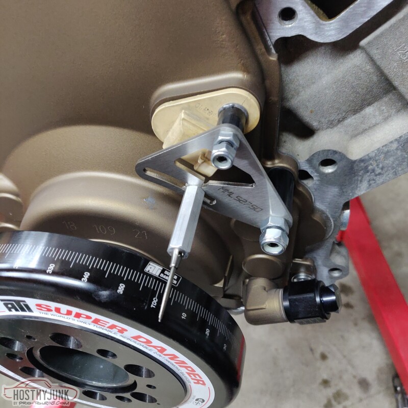
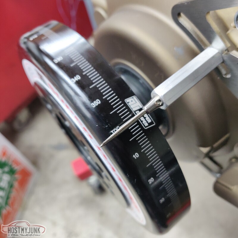
My engine builder left the engine at TDC on the compression stroke, and everything seemed to line up perfectly. I do have a piston stop, so I may verify TDC at some point to make sure it is perfect. I ordered a kit with a slightly longer pointer, but it will be easy to trim it back.
This is where I left off for the day.
Progress is being made...
Andrew
I love the little details, like the laser etched Earl's logo.
Since this is a turbo build, I felt like having the ability to confirm ignition timing was critical. The Holley mid-mount kit that I got included a fully marked ATI balancer. The balancer hub also has a key that mates with the key on the Molnar crank. This made everything pretty simple to add a timing pointer.
I chose one from Mighty Mouse solutions. It is a simple design and is inexpensive. The kit includes two studs that replace one of the front cover bolts and the cam sensor bolt.
My engine builder left the engine at TDC on the compression stroke, and everything seemed to line up perfectly. I do have a piston stop, so I may verify TDC at some point to make sure it is perfect. I ordered a kit with a slightly longer pointer, but it will be easy to trim it back.
This is where I left off for the day.
Progress is being made...
Andrew
The following users liked this post:
The BallSS (03-09-2022)

The following users liked this post:
Pro Stock John (03-09-2022)
03-11-2022 | 05:03 PM
#115
Thread Starter
Joined: Mar 2003
Posts: 10,244
Likes: 1,533
From: The City of Fountains
I searched all over for a Y-pipe that I could use to split my 4" downpipes into dual 3" pipes, but nothing was popping up. Then I saw Jody's Chevelle build over on lateral-g and he has this beautiful part from Burns Stainless. I called up Burns and 5 weeks later got this gem.
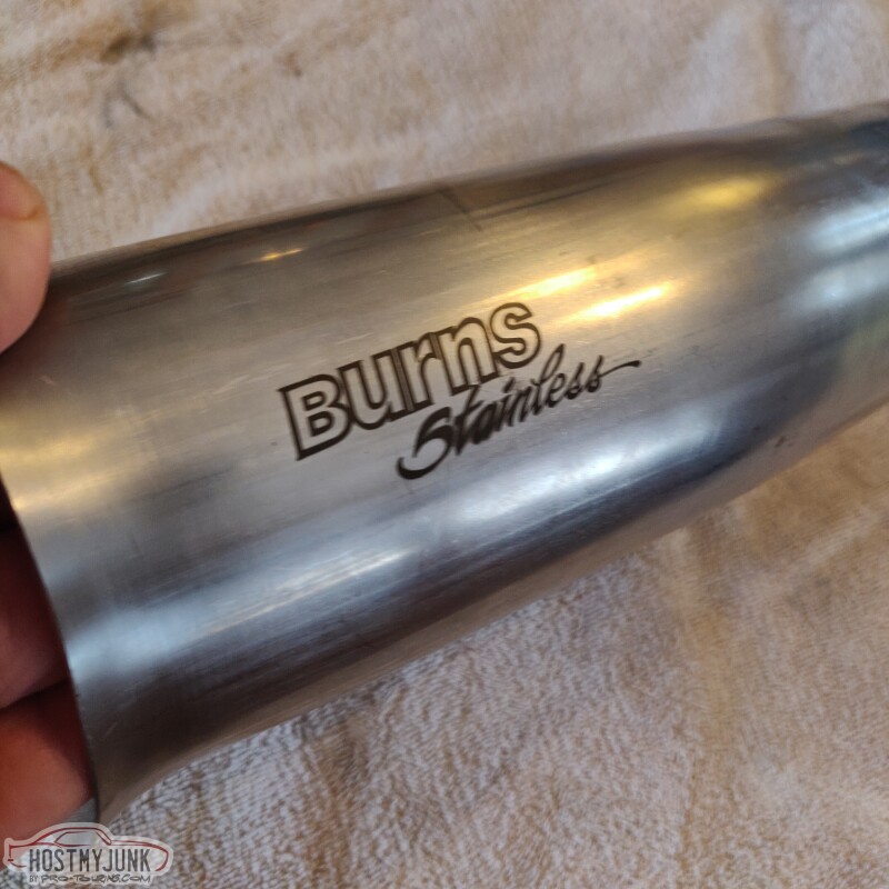
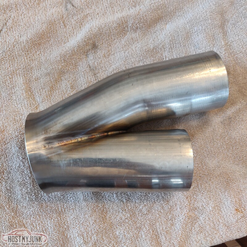
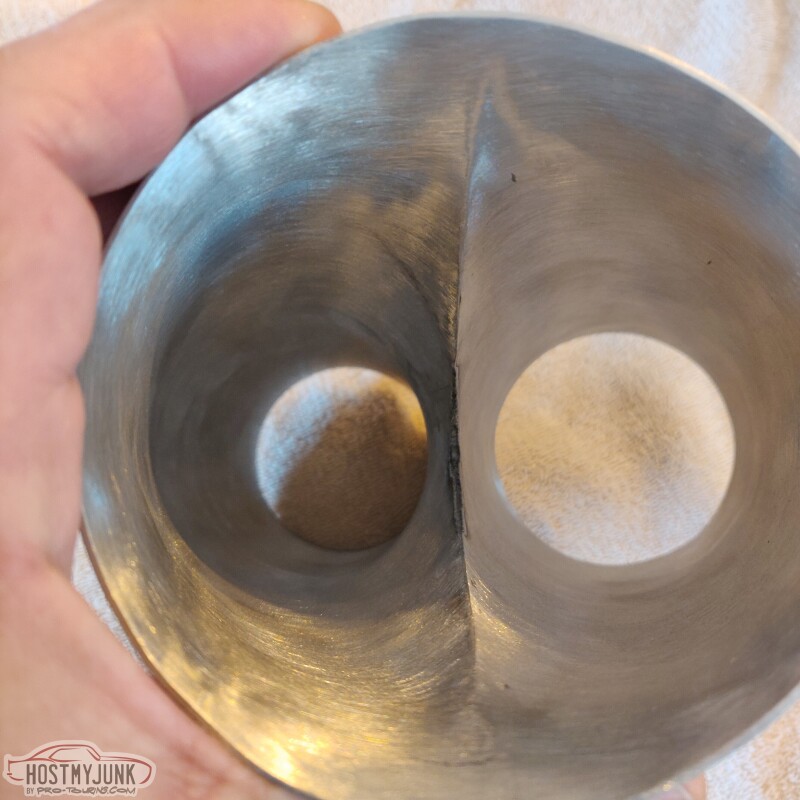
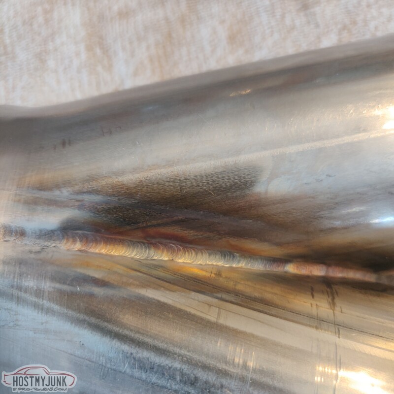
It has a nicely smoothed transition and great welds. Very happy with this part.
Andrew
It has a nicely smoothed transition and great welds. Very happy with this part.
Andrew
03-11-2022 | 05:16 PM
#116
Thread Starter
Joined: Mar 2003
Posts: 10,244
Likes: 1,533
From: The City of Fountains
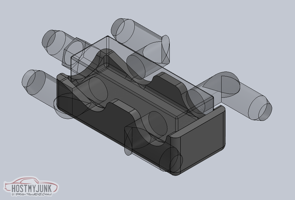
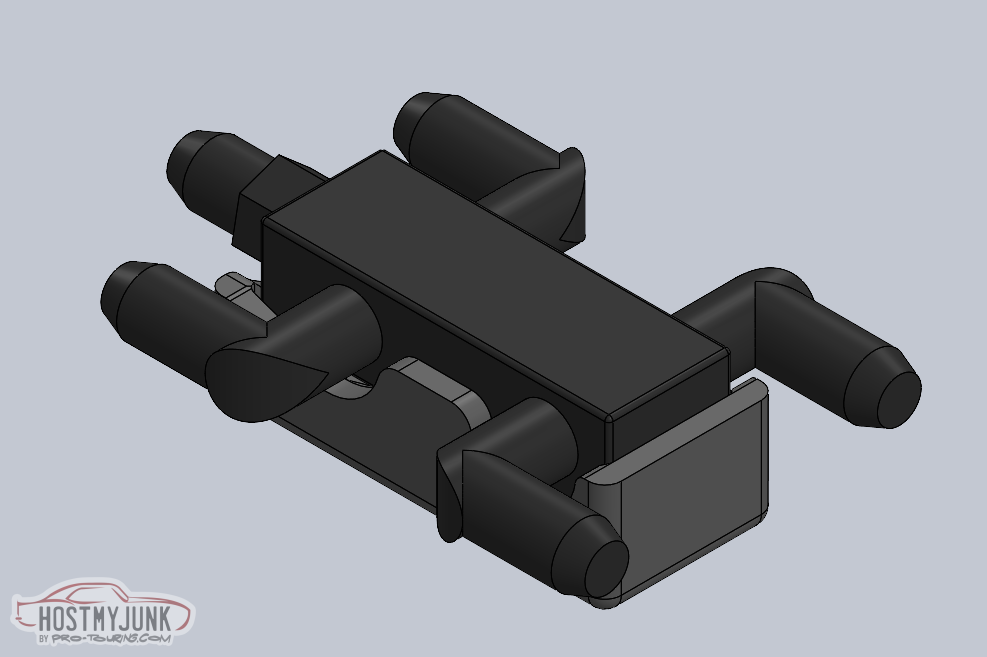
It's also totally awesome to have a friend that can whip stuff up like this and 3D print the parts out of ABS.
According to the 3M spec sheet, this stuff:
Is good for sustained 300 degrees F.
Andrew
According to the 3M spec sheet, this stuff:
Is good for sustained 300 degrees F.
Andrew


The following users liked this post:
Project GatTagO (03-14-2022)
03-14-2022 | 10:37 AM
#118
Thread Starter
Joined: Mar 2003
Posts: 10,244
Likes: 1,533
From: The City of Fountains
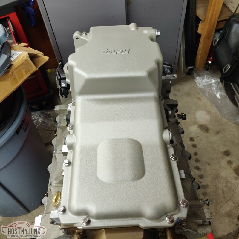
Not much progress to report. Yesterday I got some more engine parts out and did some mocking up.
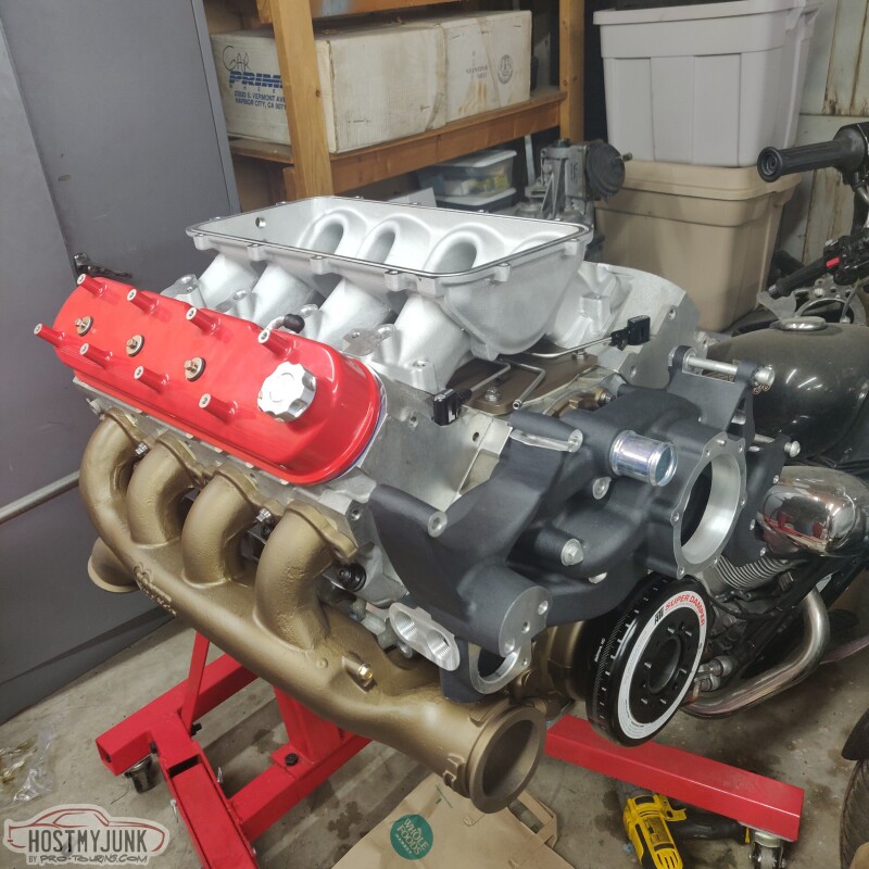
The Holley LowRam is a lot lower than I expected, especially in the valley area. The steam vent tubes actually touch the ribs on the underside of the intake. I'll probably end up bending them a little so they don't make contact.
Does anyone have any thoughts on the piping size from the compressor to the throttle body?
Andrew

The following users liked this post:
Project GatTagO (03-14-2022)