


Building a sequential turbo system
Thanks for the kind words guys!
They are 61mm compressors with .60 A/R housings with p trim T4 turbines and .48A/R T3 turbine housings. Don't worry about memory, mine sucks too. That's why I like posting brain storming posts in these threads so I can document what I was thinking about!
It's American Idol season so the wife relegated me to garage until we get the the finals at least.  Kidding, she's actually enjoying the smile I get every time I fire up the welder!
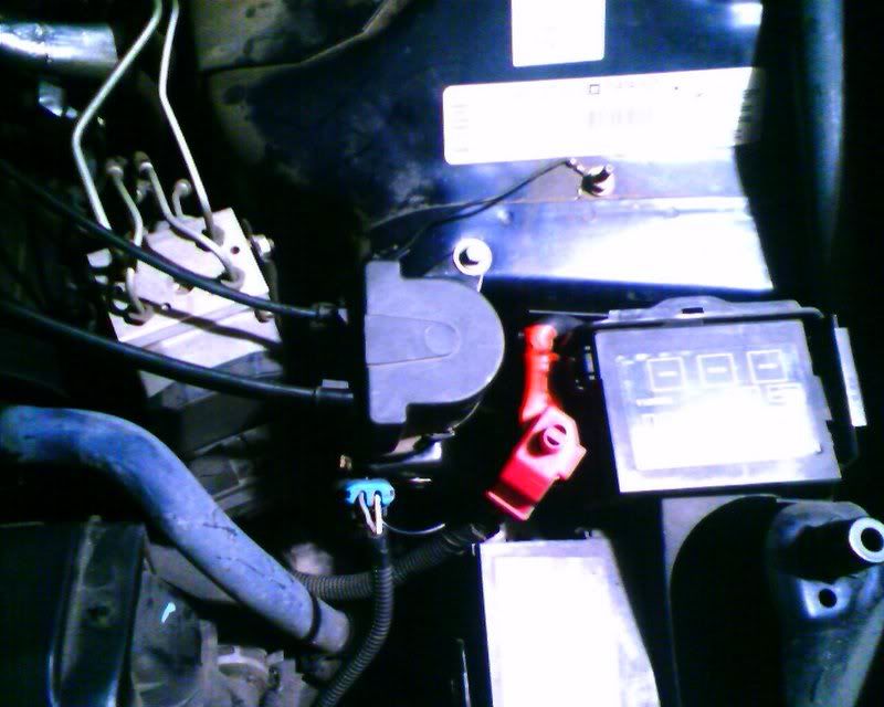
I did relocate the traction control motor to the other side of the car so I can make room for the turbos. Sorry if I'm boring everyone with all these goofy little details. I thought they might help someone needing to use a similar solution.
Originally Posted by chuntington101
hey speed, time to get off the computer and get fabbing agian!  what are the specs on the turbos agian????? (sorry memorys crap! lol)
Chris.
what are the specs on the turbos agian????? (sorry memorys crap! lol) Chris.
Originally Posted by red90cobra
damn man you've done alot of work. If had only that much dedication to this stuff. I get burnt out of it.
Kidding, she's actually enjoying the smile I get every time I fire up the welder!I did relocate the traction control motor to the other side of the car so I can make room for the turbos. Sorry if I'm boring everyone with all these goofy little details. I thought they might help someone needing to use a similar solution.
dude, the "goofy little details" are what make it happen! So what do you think the chances are that you'll market this when you're done? (obviously depending on the results... lol)
Well lots of stuff done this weekend but none of it terribly interesting. I installed my Koni SAs (not the first time but each time I mess with the front struts, any progress I think I've made in anger management is reversed). I also ran a 4ga wire from the alternator directly back to the battery and terminated starter power at the fuse panel power pin and modified the engine ground to clearance for the exhaust on that side. I installed a 175 amp fuse last weekend and now I should be good to go with a kill switch as soon as I figure out how I want to mount it. I also installed C5 brakes on the front last weekend as well. As anyone who has ever built a turbo system from scratch knows, much of the development time is spent staring into the engine bay or lying on the floor underneath daydreaming about exhaust and induction routing. Well when I had the starter off, I got a little better look up into the area between the engine and chassis.
As I mentioned a while back, I prefer not using log manifolds where possible and I think I've come up with a route that will allow me to bring the cross-over pipe up under a forward facing header and join just above the AC compressor. The goal with this kit was to retain all the stock equipment to the greatest extent possible. I also want to be able to change plugs without removing the header. I think this setup will let me do that but I won't know more until build time comes (hopefully I'll actually mount and finish the exhaust portion of the system this weekend). Then I'll liven things up a bit for you guys watching this slow progress.
As I mentioned a while back, I prefer not using log manifolds where possible and I think I've come up with a route that will allow me to bring the cross-over pipe up under a forward facing header and join just above the AC compressor. The goal with this kit was to retain all the stock equipment to the greatest extent possible. I also want to be able to change plugs without removing the header. I think this setup will let me do that but I won't know more until build time comes (hopefully I'll actually mount and finish the exhaust portion of the system this weekend). Then I'll liven things up a bit for you guys watching this slow progress.
Last edited by Speed; Mar 5, 2007 at 07:47 AM.
LS1 Tech Stories
The Best V8 Stories One Small Block at Time

Topdon ONE vs. Artidiag 800 BT2: Which is the Diagnostic Tablet For You?
Pouria Savadkouei
Gas Monkey Built a 6-Wheel Ferrari Testarossa With a Corvette LT4 Engine
Verdad Gallardo
7 Most Reliable High-Performance Engines GM Has Ever Built
Verdad Gallardo
Amazing '71 Camaro Restomod Is Modern Muscle Car Under the Skin
Verdad Gallardo
6 Common C5 Corvette Failures and What's Involved In Repairing Them
Pouria Savadkouei
Retro Modern Bandit Pontiac Trans AM Comes With Burt Reynolds' Autograph
Verdad Gallardo
Top 10 Greatest Cadillac V Series Performance Models Ever, Ranked
Pouria Savadkouei
Top 10 Most Powerful Chevy Trucks Ever Made!

Hennessey's New Supercharged Silverado ZR2 Has 700 HP
Verdad Gallardo
TECH Addict
Joined: Aug 2004
Posts: 2,866
Likes: 4
Originally Posted by Speed
Just seen the new LSX block is out there. hmmmmmmmmmmmmmmmmmmmmmmmmmmmm
would def spool the turbos quicker! lol
Chris.
Yeah lol. I've been toying with the idea for a while. I'm just trying to balance the fact that LS1 blocks have supported my power goals already. Do I really need an iron race block for a daily driver that sees as much time on the road course as it does on the drag strip?
Anyway, got a box of pipe and a catch can from Jeg's last night. I made this little bracket and installed the can just in front of the radiator. It sits somewhat under the upper rad support and uses one of the rad cover bolts to fasten it in place. It's bent in such a way so to tuck it up under the upper radiator support to clearance for the as yet undecided induction route. The bracket was made from 1.5x.125 aluminum strap from good ol Lowes. With the other odds and ends out of the way, we are now clear for the mechanical fabrication. I'm lacking v-band clamps and primary tubes for the headers at this point. IF they hit the ground this weekend, I'll start building the exhaust side. I'm not getting my hopes up for this weekend........
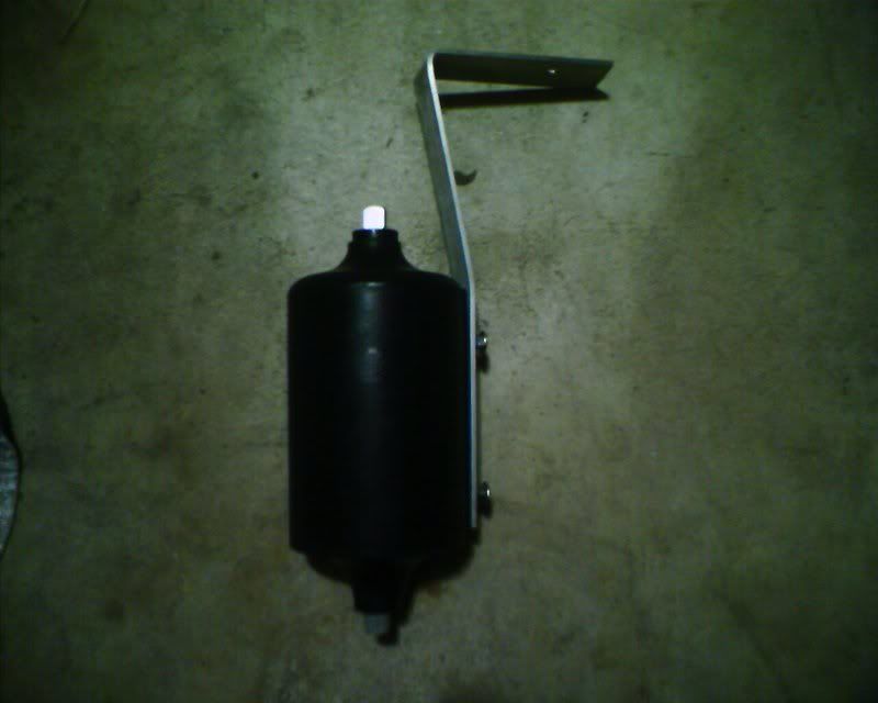
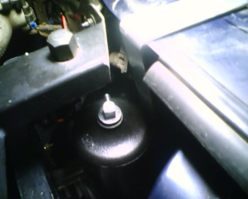
Anyway, got a box of pipe and a catch can from Jeg's last night. I made this little bracket and installed the can just in front of the radiator. It sits somewhat under the upper rad support and uses one of the rad cover bolts to fasten it in place. It's bent in such a way so to tuck it up under the upper radiator support to clearance for the as yet undecided induction route. The bracket was made from 1.5x.125 aluminum strap from good ol Lowes. With the other odds and ends out of the way, we are now clear for the mechanical fabrication. I'm lacking v-band clamps and primary tubes for the headers at this point. IF they hit the ground this weekend, I'll start building the exhaust side. I'm not getting my hopes up for this weekend........
Last edited by Speed; Mar 6, 2007 at 02:53 PM.
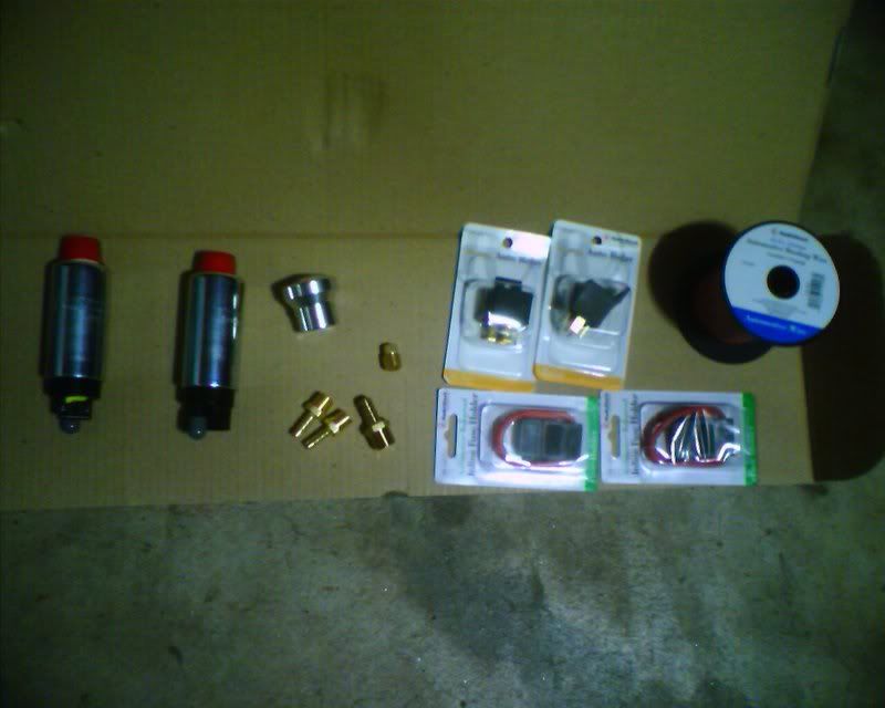
Got my fuel pumps on order today. Going with twin GSS340s which should be more than adequate to support my power needs. The only negetive thing I've read about that setup is not knowing you've lost a pump until it's too late. I think I am going to plumb in a sensor that will drop the boost to minimum in the event of pressure drop as an added safety measure.
Last edited by Speed; Mar 8, 2007 at 09:08 AM.
TECH Addict
Joined: Aug 2004
Posts: 2,866
Likes: 4
stick with the ally block! you wont need the extra power anyway with the turbo system.
over here (uk) people manly run a open track days and hilclimb/sprint evnets. the track day guys show what works after 20minuiets of HARD driving! adn big power is not allways a bonus. dont forget you got to get rid of all the heat you make.
the sprint/hillclimbn guys are insane! they push their cars really to the limit and have to know exsactly whats they car will do and have total trust in it. and some of the machinery in insane. imagine mini F1 cars running 1 (or even two!!!!) 1000cc bike engines.
what im getting at is that its all about the dilivery and how you put it to the ground. your system hopefully will give you the adjustability of an N/A setup but with the overall power of a turbo. and thats what will make you fast! i have sene it happen beofre, turbo cars get setup to make loads of power and they are slow. they go back and get the cars mapped, run boost linked to throttle possition, and all of a sudden they are fast. cos now they can get the power down and they can handle all the power they have.
also its you have to finish before you can win. power will break things!
sorry about that rant speed, i know you know what im talking about just nice to throw the ideas at someothers that might be reading this.
Thanks Chris.
Well that's where I'm at really. I don't want the extra weight and stock LS1 blocks have been running around the 1krwhp range. I'll never hook that kind of power on a road course or street. For the rather limited time it might spend near that power level on a drag strip or dyno, I think it will be fine. But that's a whole build thread away.
I started working on the fuel pump setup and for now, aside from the twin pumps, I am going to use the stock lines and regulator. They should be more than adequate for my current goals of 500-600rwhp. I'm after spool time which equates to power under the curve more than peak power right now. I'll bring the big boost (and big ticket engine rebuild I'm sure) in later.
For wiring, I'm going fat with the juice in that each pump will have an 8 gauge wire run to it via it's own 20 amp relay. Bigger is better they say. The pumps will be connected to the 1 gauge power wire from the battery at the cutoff switch which means a very short run of about 3 feet each from source. There will be no lack of current available for these pumps to use! The primary relay will be switched using the stock power wire for the pump while the secondary relay will be switched by the controller. The controller can activate the second pump on any set of parameters and pulse it if need be.
Last edited by Speed; Mar 7, 2007 at 04:28 PM.
Got the dual intank pumps installed last night and finished buttoning up today. I do have one issue that one pump is only holding about 28psi at idle. The other one works fine. Anyway, as always, here are some pics:
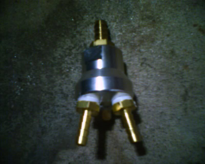
Some major pieces
The infamous shower head y-block. It's an aluminum air distribution block for air compressors available from Home Depot.
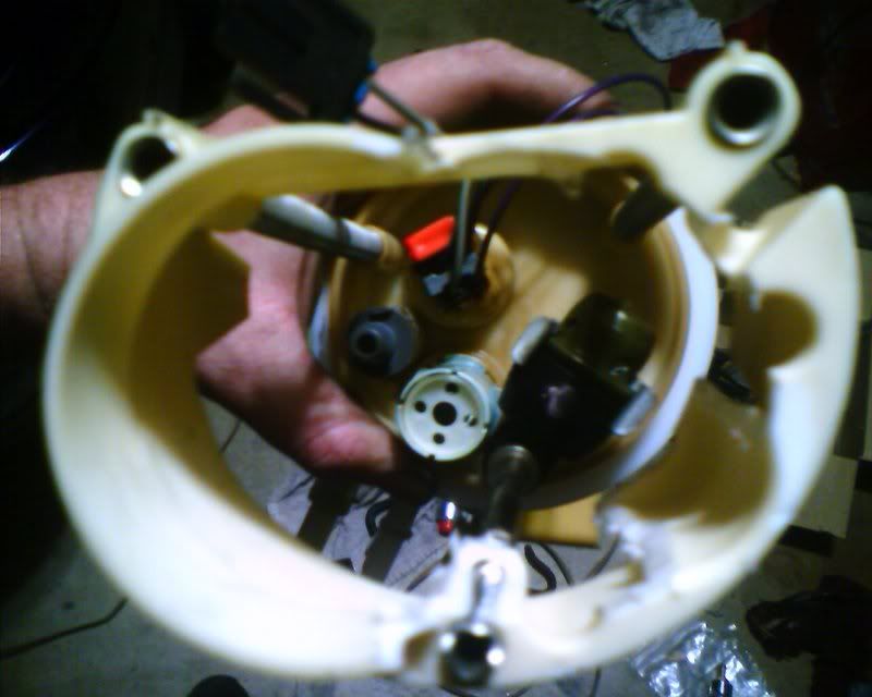
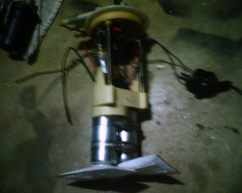
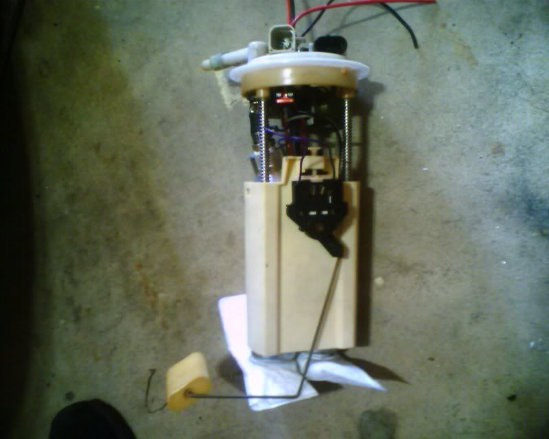
Here is the bottom of the fuel pump carrier. I just used a 2 inch hole saw and a careful touch and clearanced for the second pump.
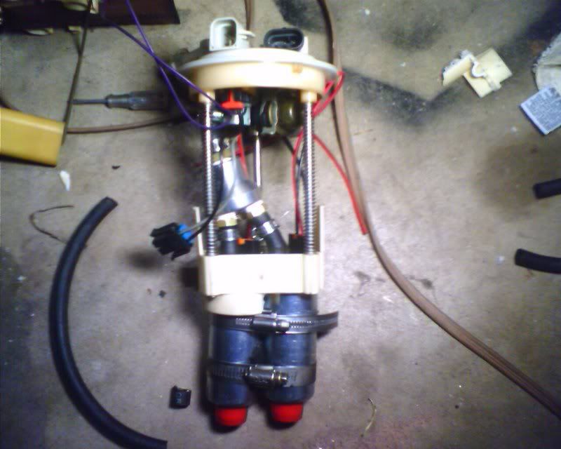
Fuel pumps installed. You can see how I put the shower head in. I didn't get good pics of this but I just used the formed hose that came with the pumps and cut it to use the bends in the hose to facilitate a clean transition in the angles. I cut the top barb down to 2 barbs which was a bit longer than the clamp was thick. I cut one of the two pump barbs down to 3 barbs to make room for the curve.
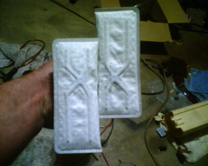
Filters installed
Carrier assembled
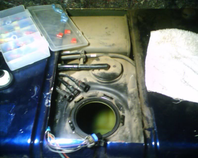
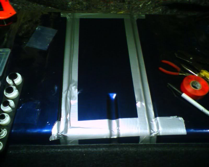
Good 'ol trap door mod
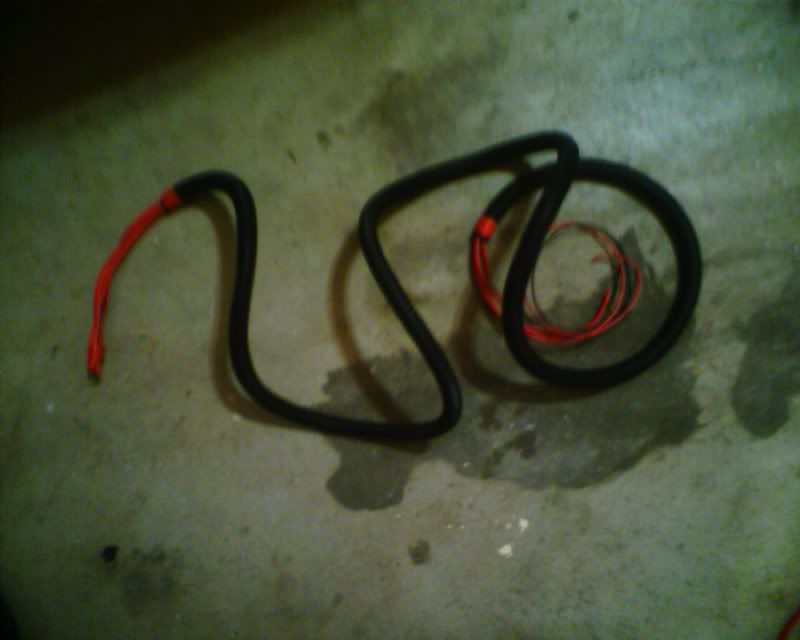
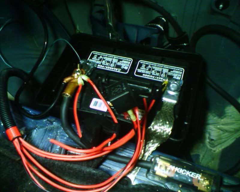
Here is the harness I built. Ended up using about 5 feet of 10ga wire for both power and ground and each supply and ground terminates on the battery. How's that for a hotwire kit. I used the original power and ground wires from the stock pump to trigger the relay for the primary pump. The secondary pump will be powered via a relay triggered by the controller.
Here is the wiring connect at the pump. Since I clipped the original power and ground wires off the stock harness I ran all four wires out of a hole I drilled in the top. I sealed the hole with RTV on the top and bottom.
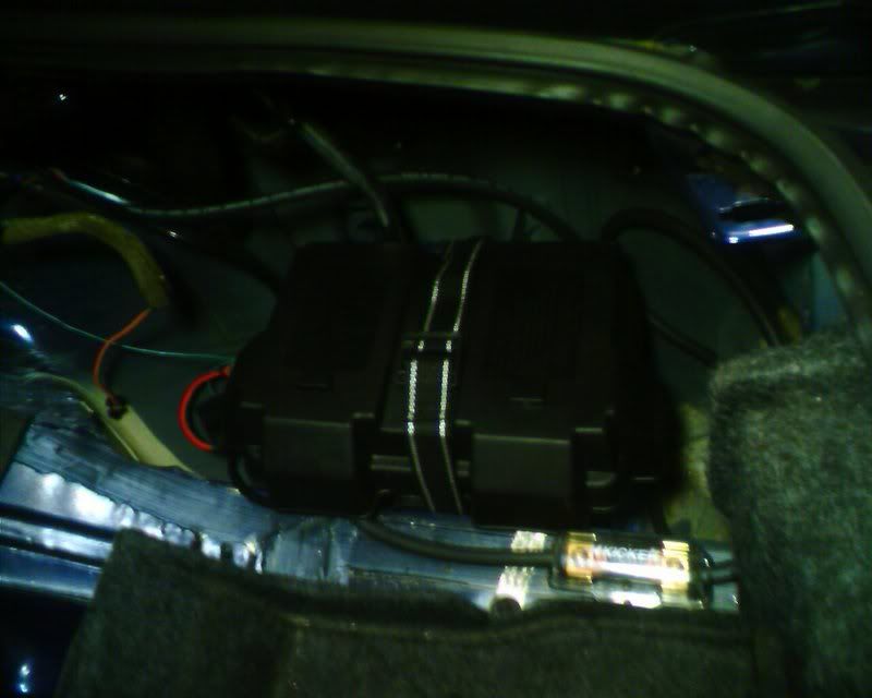
Relay and such roughed in at the battery box. I used the same spool of red wire for power and ground. Each wire is numbered and the positive wires have the connectors reversed so it's not possible to plug the pump in backwards. Just for kicks, I put some black heat shrink on the negative wires.
The way this is setup, the pumps would fit in the stock bucket just fine but I opted to bring the filters into the open tank to ensure there was plenty fuel available for the pumps. Thinking about it, I don't see how submerging the pump(s) is going to cool the pump significantly more than the 255 liters per hour of fuel already flowing through the middle of them. In any case, I keep my tank over half full by habit so I'm not worried about it either way.
I just cut bottom off of the bucket. I didn't cut holes in the side of the bucket because I wanted the bucket to act as something of a baffle to keep fuel from sloshing away from the pumps under hard corners, acceleration, or braking. The pumps are ancored to the carrier with safety wire.
God bless duct tape. A few tack welds and the duct tape will keep everything in place and dry until I put a hinge and latch on it. I plan on doing that when I swap out the fuel lines for some steel braided garden hose.
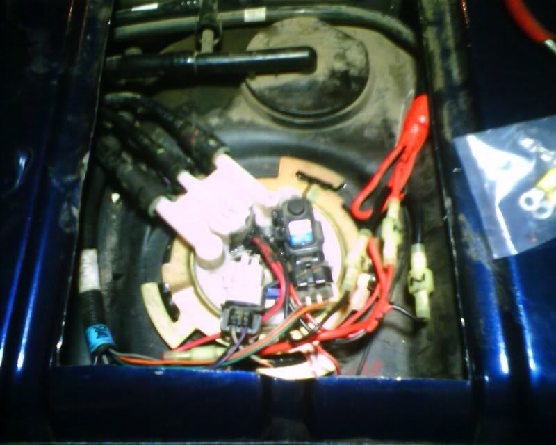
All tucked away
Some major pieces
The infamous shower head y-block. It's an aluminum air distribution block for air compressors available from Home Depot.
Here is the bottom of the fuel pump carrier. I just used a 2 inch hole saw and a careful touch and clearanced for the second pump.
Fuel pumps installed. You can see how I put the shower head in. I didn't get good pics of this but I just used the formed hose that came with the pumps and cut it to use the bends in the hose to facilitate a clean transition in the angles. I cut the top barb down to 2 barbs which was a bit longer than the clamp was thick. I cut one of the two pump barbs down to 3 barbs to make room for the curve.
Filters installed
Carrier assembled
Good 'ol trap door mod
Here is the harness I built. Ended up using about 5 feet of 10ga wire for both power and ground and each supply and ground terminates on the battery. How's that for a hotwire kit.
I used the original power and ground wires from the stock pump to trigger the relay for the primary pump. The secondary pump will be powered via a relay triggered by the controller. Here is the wiring connect at the pump. Since I clipped the original power and ground wires off the stock harness I ran all four wires out of a hole I drilled in the top. I sealed the hole with RTV on the top and bottom.
Relay and such roughed in at the battery box. I used the same spool of red wire for power and ground. Each wire is numbered and the positive wires have the connectors reversed so it's not possible to plug the pump in backwards. Just for kicks, I put some black heat shrink on the negative wires.
The way this is setup, the pumps would fit in the stock bucket just fine but I opted to bring the filters into the open tank to ensure there was plenty fuel available for the pumps. Thinking about it, I don't see how submerging the pump(s) is going to cool the pump significantly more than the 255 liters per hour of fuel already flowing through the middle of them. In any case, I keep my tank over half full by habit so I'm not worried about it either way.
I just cut bottom off of the bucket. I didn't cut holes in the side of the bucket because I wanted the bucket to act as something of a baffle to keep fuel from sloshing away from the pumps under hard corners, acceleration, or braking. The pumps are ancored to the carrier with safety wire.
God bless duct tape. A few tack welds and the duct tape will keep everything in place and dry until I put a hinge and latch on it. I plan on doing that when I swap out the fuel lines for some steel braided garden hose.
All tucked away
TECH Addict
Joined: Aug 2004
Posts: 2,866
Likes: 4
nice work speed! have you not thought about using a swirl pot for the fuel????
i have heard of some guys running lean cos of the lateral G's pulling all the fuel away form the pump (also under very hard breaking).
thanks Chris.
i have heard of some guys running lean cos of the lateral G's pulling all the fuel away form the pump (also under very hard breaking).
thanks Chris.
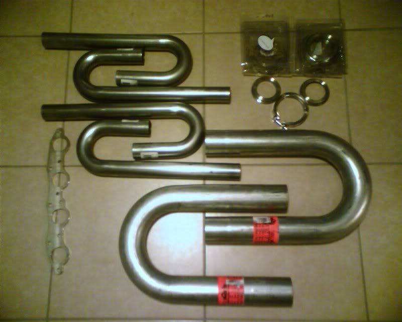
Allllllllright ladies and gentlemen.. LETS GET READY TO RUMBLE!! Got clamps, got pipes, got flanges, got bends, got a pretty new auto-darkening helmet, let's see what we can do with this stuff. Yeah, there's more, just couldn't hit it all on the kitchen floor!

God what a weekend. I could have built three truck manifold kits for the amount of effort I put into coming up with this lol. So much laying under the car or on top of it staring and fitting little pieces of pipe this way and that.
I built a header and a 2.5in up pipe for the drivers side exhaust. I cut and tacked together the primary tubes for the passenger side header and even welded one up! Then I just started staring at it and didn't like it. The header looked kind of slick in and of it self but all that tubing, plus the up-pipe, plus the wastegate, plus the y-pipe (less than 6 inches long to merge it all together), plus... Well you get the idea. It was rapidly turning into a cluster ****. One of my previously stated project goals was to retain ease of maintenance and installation and this wasn't going to get me where I wanted to be. Since an untuned tubular header was nothing more than eye candy I backed off and revisted the tubular log manifold idea.
My problem with logs has always been a perceived lack of efficiency. Many logs I've seen just come right out and dump exhaust perpendicular to the exhaust stream. That works to get the exhaust into the manifold sure but it disrupts and slows the flow already passing through the log itself. On the flipside, I've seen some logs that introduce the exhaust at an angle which seems like it would work if the angle was great enough. So I took another flange, bolted it up and used a piece of my now defunct header idea to get a visual.
Anyway, pics are worth 1000 words so here is my book for today..
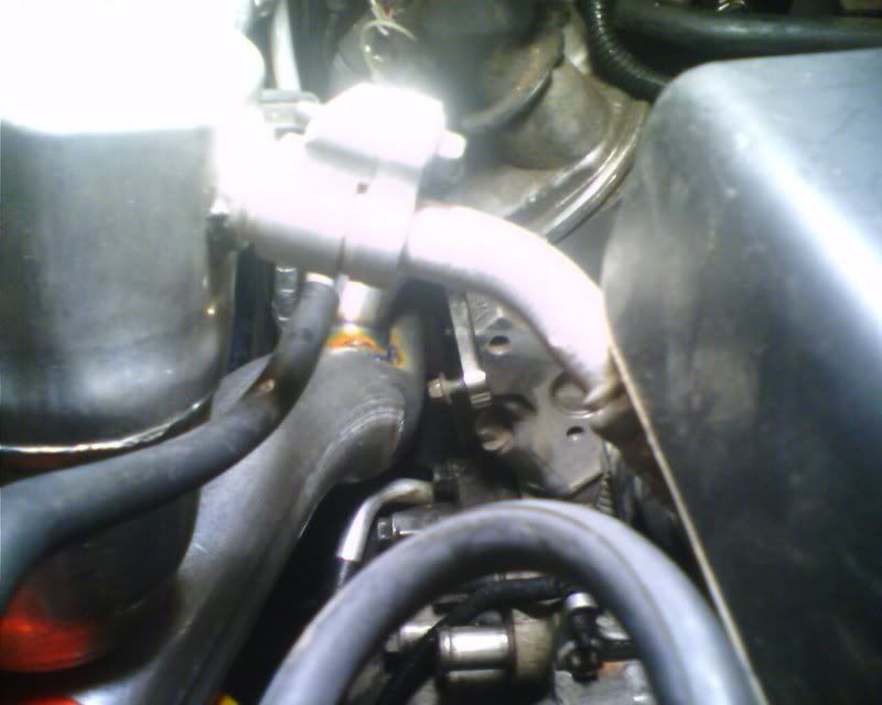
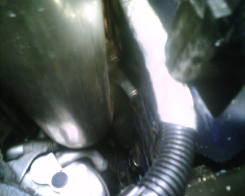
Here you can get a feel about how it jumps over the AC compressor. Final assembly gave about .75in of clearance for the aluminum inlet line.
This pic shows the number 4 welded to the log but sitting in the flange. The pic doesn't do any justice to the amount of clamps, rags, and random things used as spacers to locate the log exactly where I wanted it.
This is the log roughly mocked up. 6 and 8 were pretty easy once 4 was tacked in place and everything was located where I wanted it. But 2 was a bitch to get right.
Here is another view of how the log snakes its way over the AC and to the battery tray area.
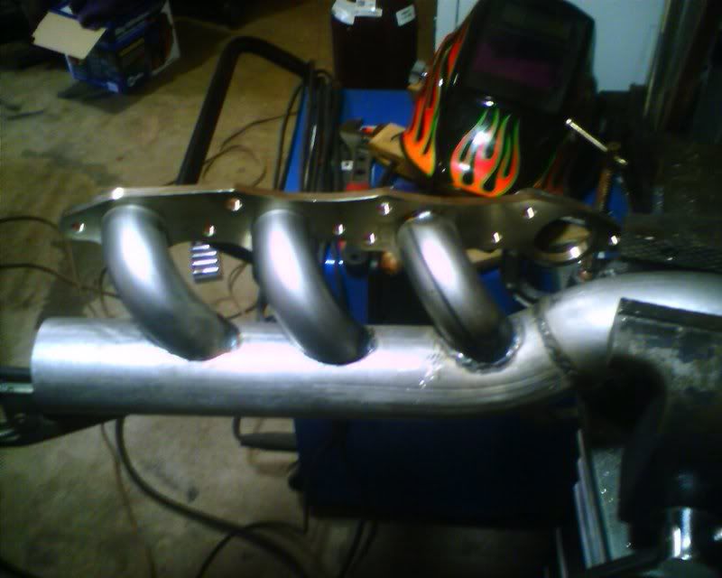
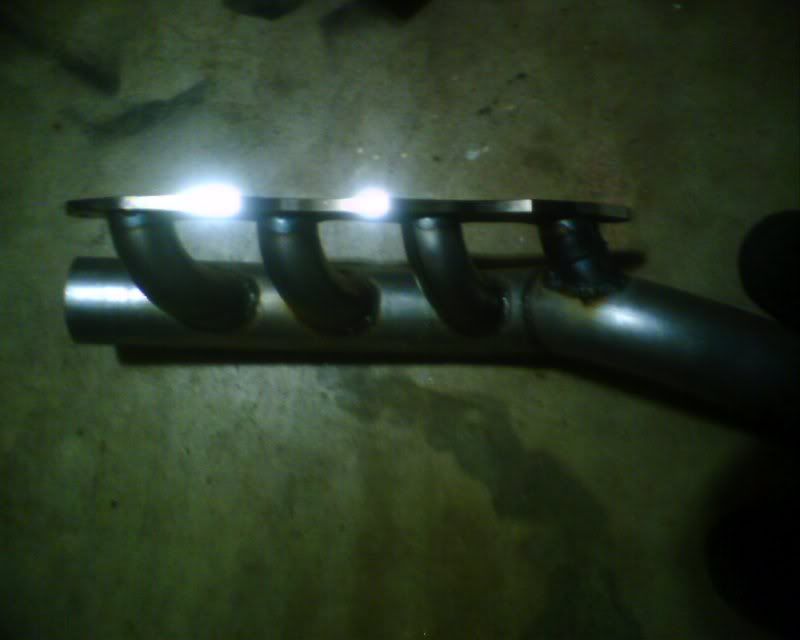
Finally, here is the completed manifold. Complete being a relative term because neither end of the log is mocked up in this pic. I'll get some better pics of how the log snakes its way around the strut tower. Most of the pipe behind 8 will get removed and a bend will point down to the ground to mate with the crossover pipe. Number 2 had two bends and fires almost straight down the pipe though that's hard to see from this pic.
The log turned out better than I had originally hoped for. Most importantly, everything clears the plug wires and boots as well as leaves the bolt holes easily accessible for installation. I'm really happy with how easy this manifold is to install and remove. The clearance around heat sensitive things like wire looms, plug wires, etc is great.
4,6, and 8 all come in at a high enough angle which should do a lot prevent reversion. You'll end up with two cigar shaped spinning flows behind each cylinder after it's exhaust pulse moves into the main air stream. They should cancel pretty quickly after each pulse and that will hopefully be the limit of turbulence through the log. 2 fires almost directly down the up pipe as it crosses the AC compressor.
I've dipped the leading each of each primary about 3/8in into the exhaust stream to help fight this spin as well as create a low pressure area at the mouth of each primary. This should help scavenge the passenger side bank a bit too. I think these benefits will outweigh the turbulence they introduce. When I get over this project, I'll build a header for the drivers side to assist with scavenging.
Anyway, the next, comes turbocharger placement and construction of the exhaust control valve which I will work on this week. To say the fun has only just begun is an understatement.....
I built a header and a 2.5in up pipe for the drivers side exhaust. I cut and tacked together the primary tubes for the passenger side header and even welded one up! Then I just started staring at it and didn't like it. The header looked kind of slick in and of it self but all that tubing, plus the up-pipe, plus the wastegate, plus the y-pipe (less than 6 inches long to merge it all together), plus... Well you get the idea. It was rapidly turning into a cluster ****. One of my previously stated project goals was to retain ease of maintenance and installation and this wasn't going to get me where I wanted to be. Since an untuned tubular header was nothing more than eye candy I backed off and revisted the tubular log manifold idea.
My problem with logs has always been a perceived lack of efficiency. Many logs I've seen just come right out and dump exhaust perpendicular to the exhaust stream. That works to get the exhaust into the manifold sure but it disrupts and slows the flow already passing through the log itself. On the flipside, I've seen some logs that introduce the exhaust at an angle which seems like it would work if the angle was great enough. So I took another flange, bolted it up and used a piece of my now defunct header idea to get a visual.
Anyway, pics are worth 1000 words so here is my book for today..
Here you can get a feel about how it jumps over the AC compressor. Final assembly gave about .75in of clearance for the aluminum inlet line.
This pic shows the number 4 welded to the log but sitting in the flange. The pic doesn't do any justice to the amount of clamps, rags, and random things used as spacers to locate the log exactly where I wanted it.
This is the log roughly mocked up. 6 and 8 were pretty easy once 4 was tacked in place and everything was located where I wanted it. But 2 was a bitch to get right.
Here is another view of how the log snakes its way over the AC and to the battery tray area.
Finally, here is the completed manifold. Complete being a relative term because neither end of the log is mocked up in this pic. I'll get some better pics of how the log snakes its way around the strut tower. Most of the pipe behind 8 will get removed and a bend will point down to the ground to mate with the crossover pipe. Number 2 had two bends and fires almost straight down the pipe though that's hard to see from this pic.
The log turned out better than I had originally hoped for. Most importantly, everything clears the plug wires and boots as well as leaves the bolt holes easily accessible for installation. I'm really happy with how easy this manifold is to install and remove. The clearance around heat sensitive things like wire looms, plug wires, etc is great.
4,6, and 8 all come in at a high enough angle which should do a lot prevent reversion. You'll end up with two cigar shaped spinning flows behind each cylinder after it's exhaust pulse moves into the main air stream. They should cancel pretty quickly after each pulse and that will hopefully be the limit of turbulence through the log. 2 fires almost directly down the up pipe as it crosses the AC compressor.
I've dipped the leading each of each primary about 3/8in into the exhaust stream to help fight this spin as well as create a low pressure area at the mouth of each primary. This should help scavenge the passenger side bank a bit too. I think these benefits will outweigh the turbulence they introduce. When I get over this project, I'll build a header for the drivers side to assist with scavenging.
Anyway, the next, comes turbocharger placement and construction of the exhaust control valve which I will work on this week. To say the fun has only just begun is an understatement.....
Couple more pics of this weeks progress. Took the next couple of days off to get everything finished. Hopefully will have the turbochargers spinning by the weekend and can fab up the first part of the induction side which promises to be a good time.
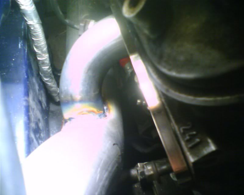
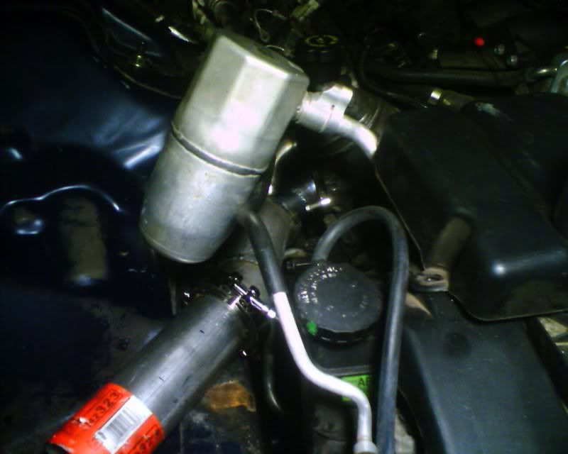
A little more detail on routing over the AC. You can see a little bit of bling on the right there.
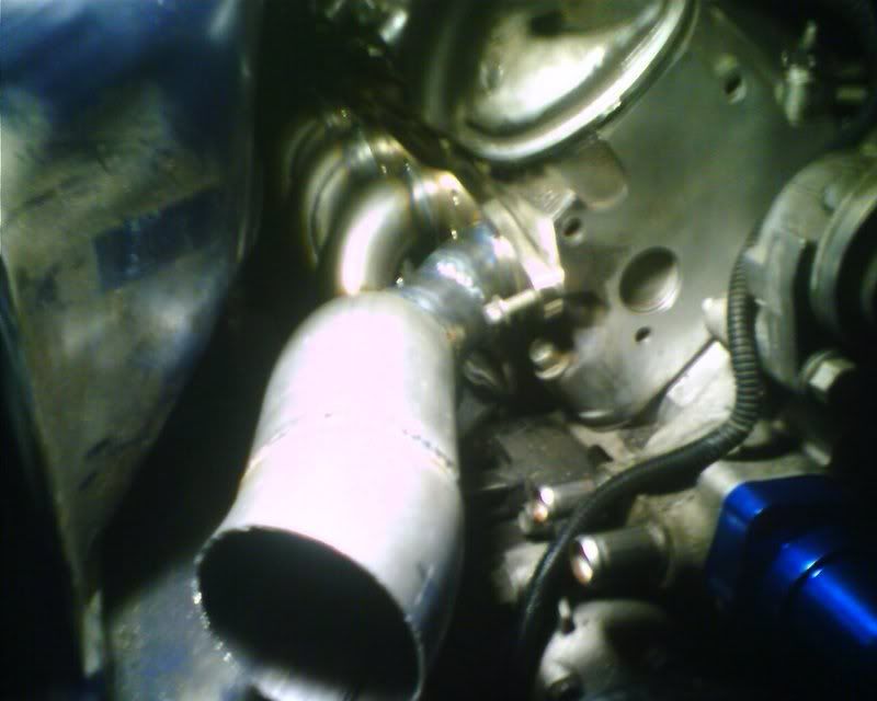
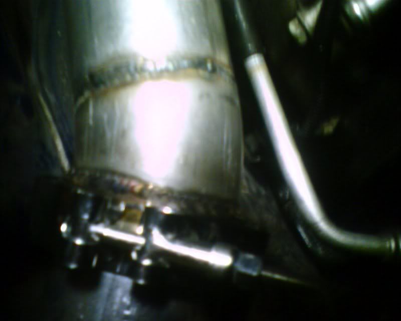
V-band clamp and a little better pic of that primary feeding into the log.
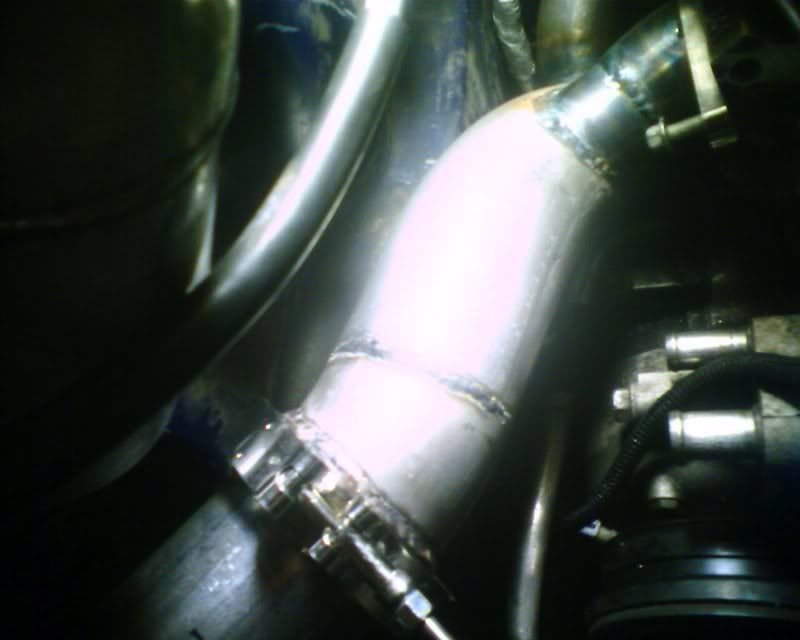
Little better overall view
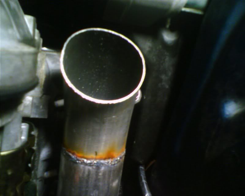
Doesn't show much but this is the entry into the log. I'll put a v-band here and feed the crossover up into it.
Again, hope you guys don't mind all the little detail posts. Hopefully this will get a bit more interesting in the next week or so!
A little more detail on routing over the AC. You can see a little bit of bling on the right there.
V-band clamp and a little better pic of that primary feeding into the log.
Little better overall view
Doesn't show much but this is the entry into the log. I'll put a v-band here and feed the crossover up into it.
Again, hope you guys don't mind all the little detail posts. Hopefully this will get a bit more interesting in the next week or so!