


Building a sequential turbo system
Thanks for the kind word guys. Money and skills just come from that time  . Tiago knows about my love for the TIG.
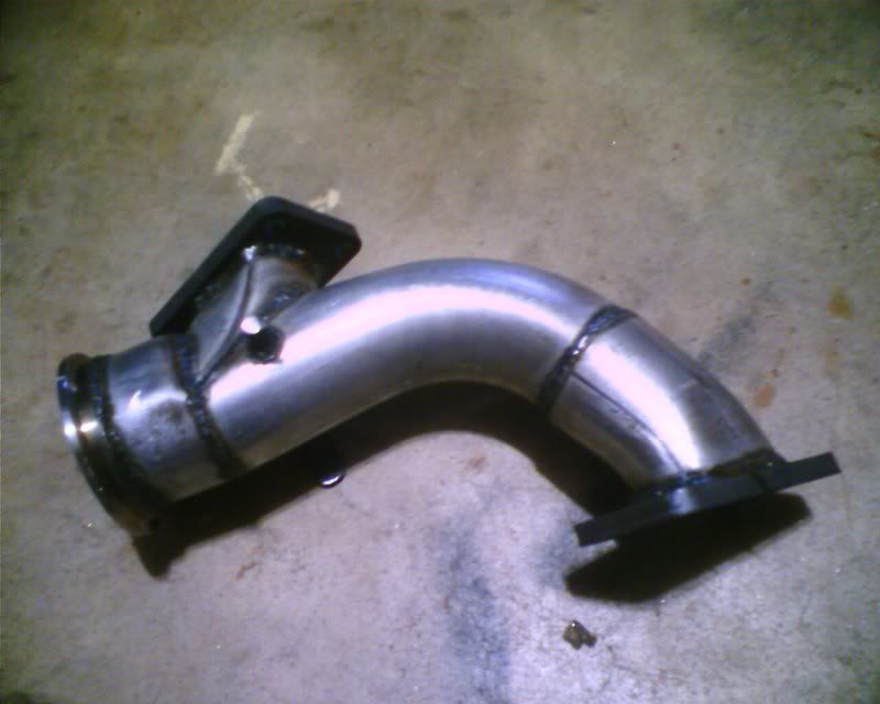
Anyway, made some more progress over the last couple days. I got the rest of the up-pipe built and turbos positioned and mounted. The up-pipe turned out to be a freaky little beast due to the routing and diverter valve positioning.
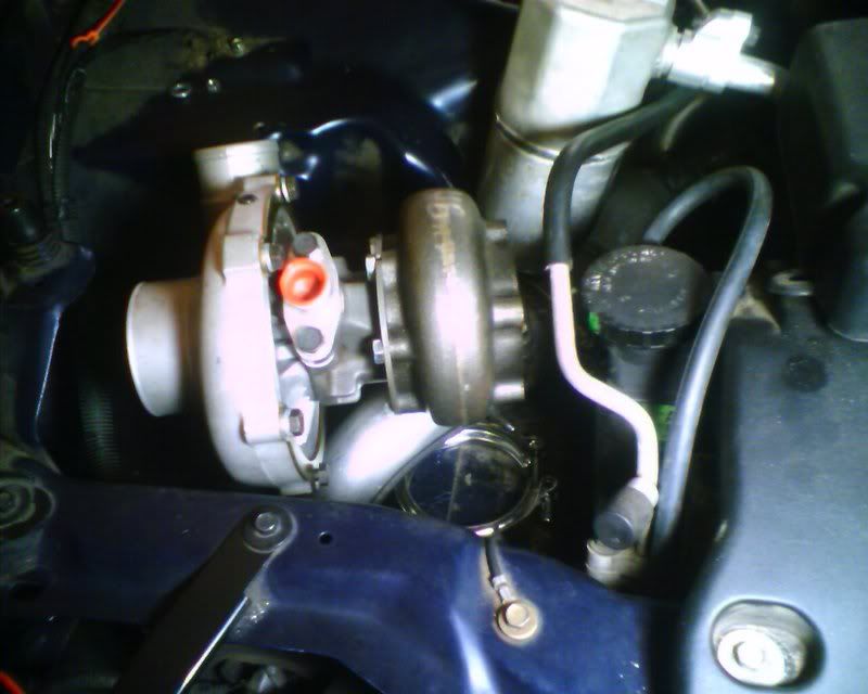
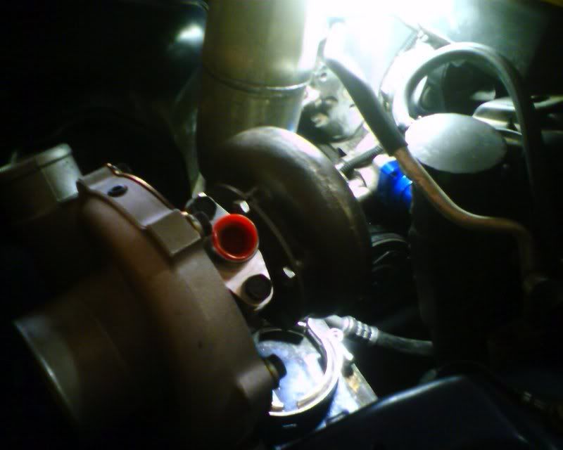
Couple pics of the primary turbo installed
. Tiago knows about my love for the TIG. Anyway, made some more progress over the last couple days. I got the rest of the up-pipe built and turbos positioned and mounted. The up-pipe turned out to be a freaky little beast due to the routing and diverter valve positioning.
Couple pics of the primary turbo installed
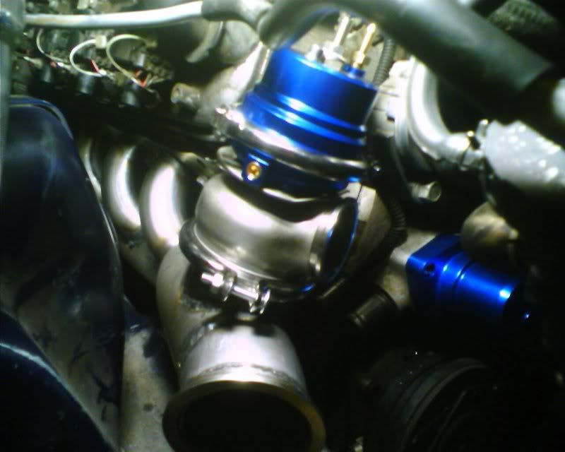
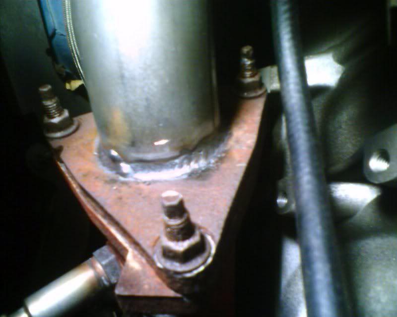
Got the wastegate installed and the log is finally mounted. Man, these big pushes to get something finished can really take a toll on the ol body. I did have one glitch though. When I installed the log I couldn't get the middle two bolts through the gasket. Finally I pulled the log and seen that I had welded the flange on backwards. Oops. In worrying about all the details of the build I got the flange right side up but backwards reversing the middle two holes. No big deal, I just redrilled the flange and it worked fine. I could have kicked myself for missing that. I guess we've had the glitch for this mission....
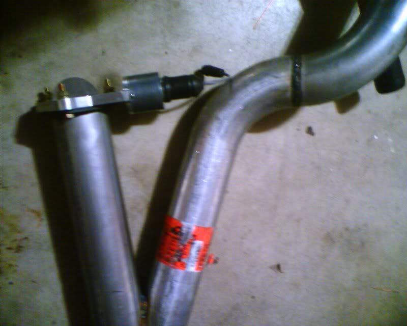
Here are a couple pics of the log. This one shows the 02 sensor bung, and wastegate flange installed.
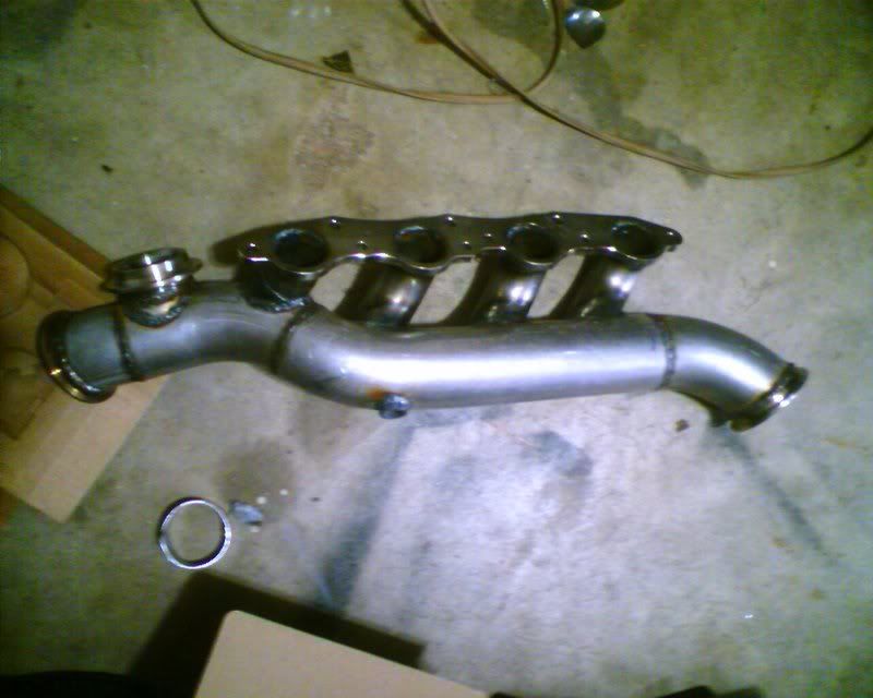
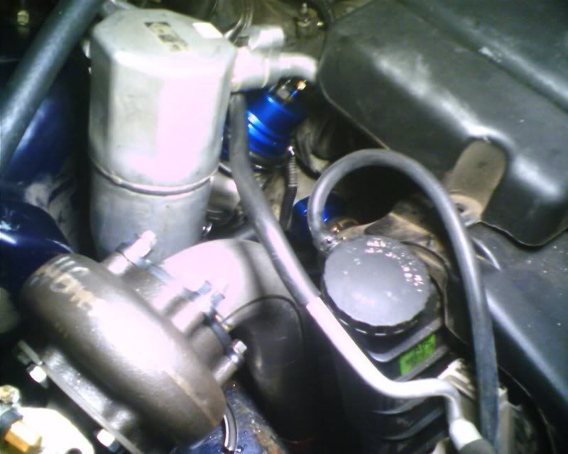
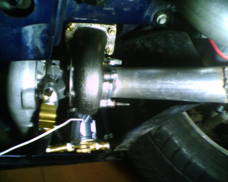
And finally buttoned up in the car. The wastegate is a 60mm TurboXS (ebay) unit. It caught my eye searching for blue wastegates. It looked neat and I was curious so I bought it. The quality seems to be good so I figured I would try it. With a 2.5in inlet and up to a 2.25in discharge, it should have no problem keeping the boost under control when I do decide to crank it up.
Also got the oil feed line installed and bracket made from some aluminum I had laying around to mount the scavenge pump but I don't have any pics of that. I'll post some up tomorrow. Hopefully I'll be able to pull the rest together tomorrow and start her up!
Here are a couple pics of the log. This one shows the 02 sensor bung, and wastegate flange installed.
And finally buttoned up in the car. The wastegate is a 60mm TurboXS (ebay) unit. It caught my eye searching for blue wastegates. It looked neat and I was curious so I bought it. The quality seems to be good so I figured I would try it. With a 2.5in inlet and up to a 2.25in discharge, it should have no problem keeping the boost under control when I do decide to crank it up.
Also got the oil feed line installed and bracket made from some aluminum I had laying around to mount the scavenge pump but I don't have any pics of that. I'll post some up tomorrow. Hopefully I'll be able to pull the rest together tomorrow and start her up!
Originally Posted by chuntington101
looking good. any chance of a engine bay pic so we can see where everything is going????
thanks Chris.
thanks Chris.

Originally Posted by Tiago
things are shaping up, awesome
While I didn't get the hot side finished as I had hoped this weekend, I'm damn close and everything is coming together pretty well. I alllllllllllmost got the crossover pipe buttoned up but a minor misalignment between pipes will require sneaking a probably 4* bend in place just to keep things flowing well. I could have cheater cut it but I have enough little chunks of bend laying around that I'm sure I have something that will work.
I will say dynomax bends suck these days. Some of them loose almost .25in in the diameter through the bend. I had a bunch of older bends that didn't seem to have this problem. This only really seems to be the case with the 16ga 2.5in bends. The 3in seemed fine.
I had a pic of the completed down pipe but it disappeared. It's a freaky little beast too. I'll get a pic up tomorrow. I am proud of this little setup. I figure if I ever get rid of the turbo system, I've got a way to plumb an apartment building.
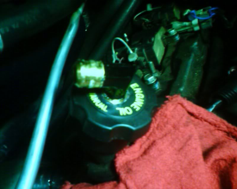
Return to the oil fill cap. At some point (when building the next motor I'm sure), I'll plumb this into the pan or timing cover but for now I think this will work nice. When I do, I'll swap it over to the 14hp mobile 1 cap.
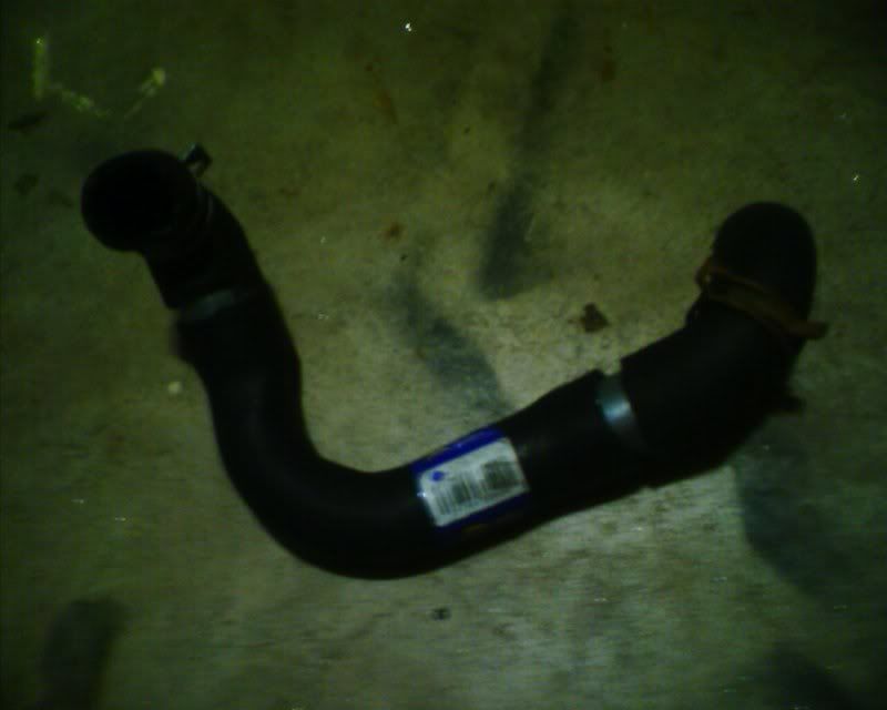
In this entire project, nothing has pissed me off more than the cooling system; namely the heater hoses. If you have ever tried to remove the clamps on the firewall bulkhead, you know what I mean. My GOD that is a pita with the engine in place. lsdkfjlasdkjfasljfa;lsdkjfas;l
Here is the rad hose I made. I found a hose at napa that had some bends I wanted in it so I used that and some of the stock hose with a couple pieces of 1.5in pipe to connect them all together. Turned out like this. Pic doesn't show it but I did put hose clamps on the splices. It's holding water fine so I hope it works lol.
Last edited by Speed; Mar 26, 2007 at 10:48 AM.
Originally Posted by Speed
In this entire project, nothing has pissed me off more than the cooling system; namely the heater hoses. If you have ever tried to remove the clamps on the firewall bulkhead, you know what I mean. My GOD that is a pita with the engine in place. lsdkfjlasdkjfasljfa;lsdkjfas;l
LOL
its the little things that get you

LS1 Tech Stories
The Best V8 Stories One Small Block at Time

Gas Monkey Built a 6-Wheel Ferrari Testarossa With a Corvette LT4 Engine
Verdad Gallardo
7 Most Reliable High-Performance Engines GM Has Ever Built
Verdad Gallardo
Amazing '71 Camaro Restomod Is Modern Muscle Car Under the Skin
Verdad Gallardo
6 Common C5 Corvette Failures and What's Involved In Repairing Them
Pouria Savadkouei
Retro Modern Bandit Pontiac Trans AM Comes With Burt Reynolds' Autograph
Verdad Gallardo
Top 10 Greatest Cadillac V Series Performance Models Ever, Ranked
Pouria Savadkouei
Top 10 Most Powerful Chevy Trucks Ever Made!

Hennessey's New Supercharged Silverado ZR2 Has 700 HP
Verdad Gallardo
Coachbuilt N2A Anteros Is an LS2-Powered C6 Corvette In Italian Clothes
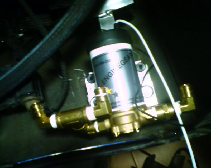
Verdad Gallardo They are all NPT and barb. Screw Lowes or Home Depot for brass fittings. Ace hardware has 10000000000000000000000 of them. The pump has 3/8s male NPT fittings on the inlet and outlet. I don't remember exactly what I used (put it all together standing in the store). On the inlet side, there are two 5/8 barb to 3/8 npt male elbows going into a 3/8 female tee. Then it connects to the pump via a male/female 3/8s npt elbow. Outlet is a female 3/8s npt coupler to a male 3/8s npt to 5/8s barb. Another 3/8s npt to 5/8s barb is installed in the oil cap.
I love seeing the "subscribing" posts lol. Sometimes I wonder if anyone besides Chris and Tiago is watch this.
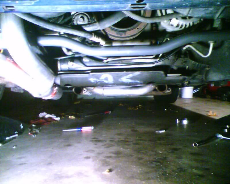
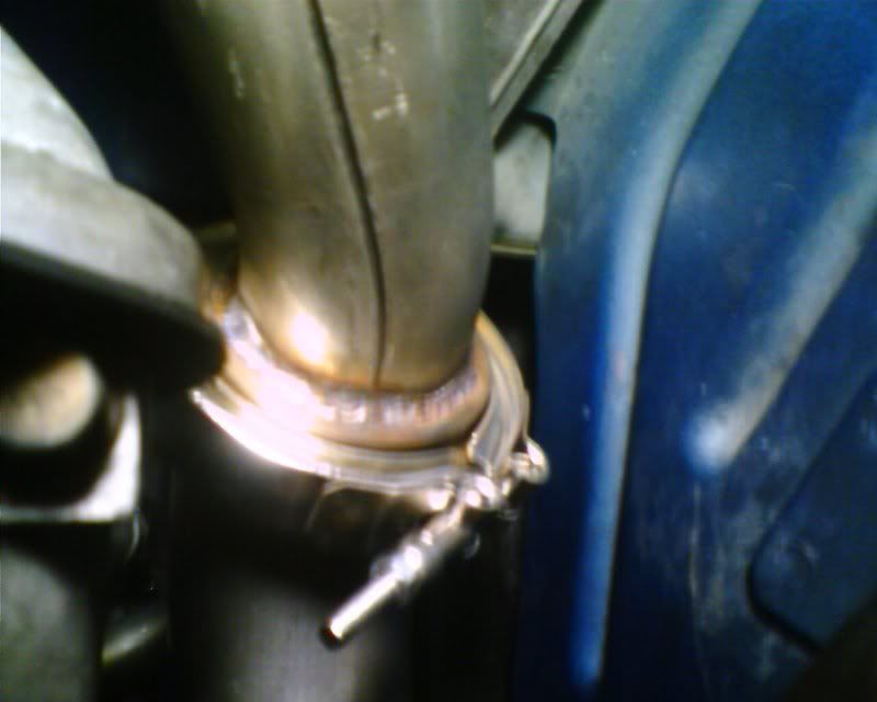
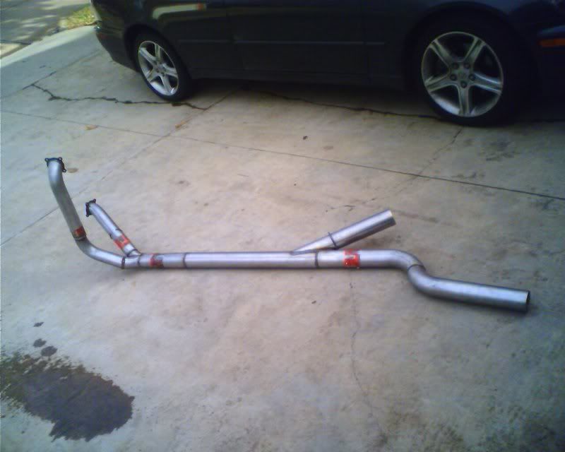
Anyway, got some great news!!! The turbos are spinning!!!!! I finished the y-pipe and essentially the catback. I made a cutout and installed a qtec I bought a while back. More pics:
Here is the bottom of the crossover. You might think by looking at it that it hangs really low but I left part of the stock y-pipe in place to show a reference. What you can't see is how low the original passenger side cat hangs. We lost no ground clearance on the crossover and less than an inch on the y-pipe.
Crossover on the stock drivers side manifold
Passenger side log
Primary turbo
Secondary turbo
y-pipe with cutout (cutout flange not installed yet)
With Q-Tec
On the car

I was playing with the control valve and it's pretty freaky to hear one turbo spinning up slower than the second one. Creates some strange sounding harmonics!
Anyway, I am going to have an exhaust shop I know make a slip fit flange for me so I can take the y-pipe off easier if I need to (all these projects require taking crap on and off and on and off).
I have one issue in that at full pressure, oil was spilling into the secondary turbine housing. I bought a brass needle valve from Ace to try and it appears to be working great! Just had to slow that oil down a bit. I might lower the scavenge pump a bit too since the secondary turbo ended up lower than I originally planned for.
Next comes the cold side build and boost!
Anyway, got some great news!!! The turbos are spinning!!!!! I finished the y-pipe and essentially the catback. I made a cutout and installed a qtec I bought a while back. More pics:
Here is the bottom of the crossover. You might think by looking at it that it hangs really low but I left part of the stock y-pipe in place to show a reference. What you can't see is how low the original passenger side cat hangs. We lost no ground clearance on the crossover and less than an inch on the y-pipe.
Crossover on the stock drivers side manifold
Passenger side log
Primary turbo
Secondary turbo
y-pipe with cutout (cutout flange not installed yet)
With Q-Tec
On the car
I was playing with the control valve and it's pretty freaky to hear one turbo spinning up slower than the second one. Creates some strange sounding harmonics!
Anyway, I am going to have an exhaust shop I know make a slip fit flange for me so I can take the y-pipe off easier if I need to (all these projects require taking crap on and off and on and off).
I have one issue in that at full pressure, oil was spilling into the secondary turbine housing. I bought a brass needle valve from Ace to try and it appears to be working great! Just had to slow that oil down a bit. I might lower the scavenge pump a bit too since the secondary turbo ended up lower than I originally planned for.
Next comes the cold side build and boost!
Looking good! I have the exact same scavenge pump, working well so far, just a bit noisey. When cutouts closed and exhaust is ran out back, you can hear the pump at idle but once you get moving the engine drowns it out. With cutouts open, you cant hear it. Where is it you mounted yours?
__________________

Featuring 6 different turbo kits for your F-body!
Check us out on Facebook at: www.facebook.com/HuronSpeed
Featuring 6 different turbo kits for your F-body!
Check us out on Facebook at: www.facebook.com/HuronSpeed
Originally Posted by Tiago
That is bad *** Bryan,
do you have any pictures of the diverter valve?
why not just install vbands into teh exhaust for easy R&R.
do you have any pictures of the diverter valve?
why not just install vbands into teh exhaust for easy R&R.
The only thing I have specifically of the diverter valve is a couple crappy videos explaining the operation that I deleted because they sucked lol. Hopefully I can show it to you first hand soon!
I ran out of 3in v-band kits but a slip fit for the back side to joint the rest of the exhaust just behind that S curve should work. I'll have to drop that whole assembly but that isn't very hard.
Originally Posted by Superman09
Looking good! I have the exact same scavenge pump, working well so far, just a bit noisey. When cutouts closed and exhaust is ran out back, you can hear the pump at idle but once you get moving the engine drowns it out. With cutouts open, you cant hear it. Where is it you mounted yours?
It is a noisy little beast for sure but I can't hear it at all with the open down pipe. I hope it's not too bad with everything quiet. I even thought about running it at a slower speed waaaaaay back when I thought it was going to pump more than the oil feeds were putting in. Yeah, starting it yesterday scrapped that idea!

Cant wait to see this in action! Your setup deserves its own promo video. 
yea ACE has a great selection. I spent a good 2 hours in there constructing fittings on the floor. Ive got the same reverso pump but i simplified the fittings to just a pair of 90* 3/8" NPT female to female and then put in 3/8" NPT male to 1/2" barb in each of those.
Also interested in that diverter valve. Got a part # for it? Where is it installed exactly?

