


PVC Catch can system.... Final conclusive answer
Okay, im still out on this sbj. Here is a diagram I found and am thinking about using. Very similar to on posted here (Post #200). I havent really looked but where does vac for the brake booster come from? I dont want to put a check valve somewhere and cause that not to get vac under boost (Brake boosting).
Also will this work with a vented catch can (which I already have just not installed.) Seems like if I unhook that hose coming off of the intake (IE: venting it to atmosphere like a vented can would) then the car wont run. I also have my reference for the BOV, and Boost gauge in that line, as long as I put the check valve before the T for that (IE Check valve, T for BOV then intake) that should still function fine right?
Also will this work with a vented catch can (which I already have just not installed.) Seems like if I unhook that hose coming off of the intake (IE: venting it to atmosphere like a vented can would) then the car wont run. I also have my reference for the BOV, and Boost gauge in that line, as long as I put the check valve before the T for that (IE Check valve, T for BOV then intake) that should still function fine right?
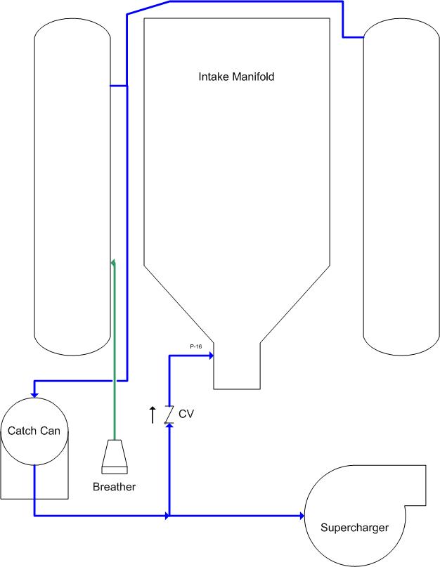
That last image is mine, and there is a slight mistake in it. I forgot a one way check valve on the line going to the blower on the bottom of the image, right of the T.
Anyway RevXtreme makes a catch can with two outlet ports specific for FI style applications. This would simplify the routing and remove the need for the two check valves. An updated image is attached to reflect that. I like the RevXtreme can as it has the check valves built in as the ports.
Anyway RevXtreme makes a catch can with two outlet ports specific for FI style applications. This would simplify the routing and remove the need for the two check valves. An updated image is attached to reflect that. I like the RevXtreme can as it has the check valves built in as the ports.
I configured mine like shown Aster diagram and it seemed to function well. I used brass Ts from Home Depot, 10 SS clamps and 2 PCV Check Valves from Auto Zone. I tried to clen it up and route the lines best I could but would love to find a better way. I have to check out the rev xtreme to see what it has to offer.
LS1 Tech Stories
The Best V8 Stories One Small Block at Time

6 Common C5 Corvette Failures and What's Involved In Repairing Them
Pouria Savadkouei
Retro Modern Bandit Pontiac Trans AM Comes With Burt Reynolds' Autograph
Verdad Gallardo
Top 10 Greatest Cadillac V Series Performance Models Ever, Ranked
Pouria Savadkouei
Top 10 Most Powerful Chevy Trucks Ever Made!

Hennessey's New Supercharged Silverado ZR2 Has 700 HP
Verdad Gallardo
Coachbuilt N2A Anteros Is an LS2-Powered C6 Corvette In Italian Clothes
Verdad Gallardo
Awesome K5 Blazer Restomod Comes With C7 Corvette Power
Verdad Gallardo
10 Camaros You Should Never Buy

10 LS Engine Myths That Refuse to Die
Verdad GallardoDo you think you can post a link to the SS ones you have? I think I might have sent you a PM on it but never got response.
 I thought I might have found them by the part # in the pic but it looked to be an international website.
  If you could clue us in that would be great.
  Thanks
 They are no longer available online, and the Hamlet company will only sell to big distributors. I have yet to find another. Sorry about the PM ran into some issues with car and family and didnt pay much attention I apologize. I am selling one in the classifieds on here for the exact same price I paid. Pricey but are tough and will last forever.

Cant you hook up a vaccum line inthe back of the intake kind of where the brake gets its vaccum from. I believe there is a check valve in it. I think it always has vaccum not positive pressure even with forced induction. If its hooked to this you wouldnt need to hook it to turbo side right?
Cant you hook up a vaccum line inthe back of the intake kind of where the brake gets its vaccum from. I believe there is a check valve in it. I think it always has vaccum not positive pressure even with forced induction. If its hooked to this you wouldnt need to hook it to turbo side right?
I just took both of my VC nipple/ports and ran some -6an line from them using tbolt clamps to secure the braided line to them and ran those 2 to one side of a 12x3" cylinder can where they were mounted horizontal with AN bungs and then a 3rd line from the intake manif. refrence to the otherside of the catch can to be able to have clean air out of the way of the oil lines while in vacuum. This line from the intake manifold has a check valve in it where it will stay in vacuum but under boost it will close into the catch can....the reason for me doing this was simply due to the catch can being vented with a one way check valve so when positive pressure is sensed from the VC lines it will allow that pressue out of the catch can.....if i were to allow the intake in i would have a boost leak right out the top of the catch can....hints the check valve....and the cyclinder has another cylinder inside of it and it is baffled with 2 angled and staggard pieces of alum....


I apologize for not reading the whole thread, but... When going turbocharged, for proper PCV functioning, can I just move PCV air intake from before throttle body to between turbo and air filter? And cap port before TB?


if your car isnt making any blowby YES but you still need to add a check valve after the pcv valve to make sure you dont leak any boost into the crank case
if you have a bigger hp engine set up a little looser then the blow by will likely be too much for the single line to the air filter to handle and you will pop out the dipstick or similar.
i have a fix comming soon i have proven out on my car
if you have a bigger hp engine set up a little looser then the blow by will likely be too much for the single line to the air filter to handle and you will pop out the dipstick or similar.
i have a fix comming soon i have proven out on my car
What did ya find homie?
I'm having a lot of smoke/vapor coming out of both my breathers and am looking for a way to get rid of that.
working on it still, starting over with can situations, i may just go with an expensive version to start out with, but people will just have to eat the extra for no good reason.. which sucks.
all i need is a 1 liter can with a drain for about 20 bux... nope everybody wants 60
all i need is a 1 liter can with a drain for about 20 bux... nope everybody wants 60

TECH Enthusiast
Joined: Dec 2004
Posts: 588
Likes: 0
From: Zanesfield, OH
There are so many posts on this. I tried looking up the post with all the configurations but I am getting the red X, like the picture link is broke.
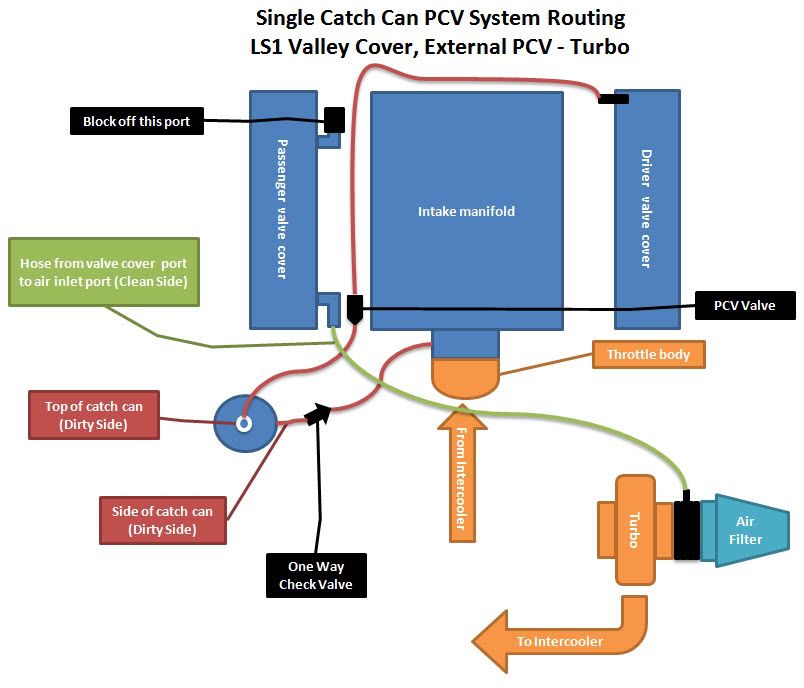
Anyway I have a procharged car and procharger says to cap the nipple on the TB and re-route the line that is from the passenger side valve cover that use to go to the TB to the intake hat on the blower.
Tell me if my plan is wrong as I want to work on it this weekend, but I plan to put a can in line between the front of the passenger valve cover to the blower intake hat. With a second can I was going to route the line with the PCV into the can and a hose back to the intake where the PCV used to go.
I dont see why I would need a check valve in this system as I am basically just taking how procharger says to route the lines and putting a catch can in the middle of each of the PCV system lines.
Of course I know procharger directions are a bit dated, LOL. So if I am missing something let me know so I can do it right.

The check valves from post #193 are made by HAM-LET. They are a Swagelok knockoff and are much less $$ compared to Swagelok stuff.. Part #is H410SSN1/2. You can get different cracking pressures.
Don't know what the secret is..why not post the info in the first place?
http://www.ham-let.com/lang1/product...&it=5&m=SS+316
Don't know what the secret is..why not post the info in the first place?
http://www.ham-let.com/lang1/product...&it=5&m=SS+316
