 [/quote]

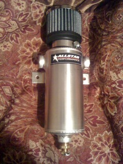
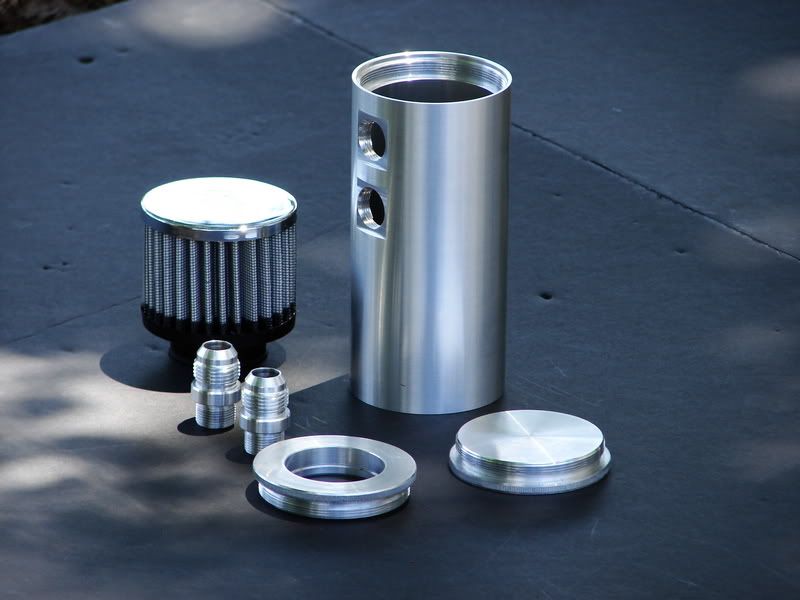
PVC Catch can system.... Final conclusive answer
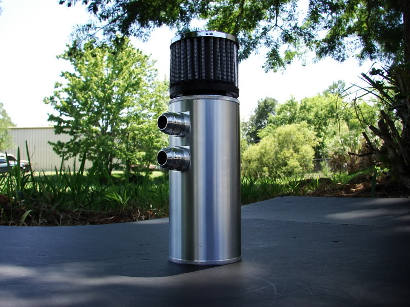
i ran each of my valve covers to 2 port catch cans. one on each side, the inlet comes from the valve cover, the outlet runs to my exhaust. When I rev the engine at idle with the lines unhooked, I can feel a substantial vacuum getting pulled from the exhaust
Is it possible for the exhaust to have back pressure and push exhaust into the valve cover?
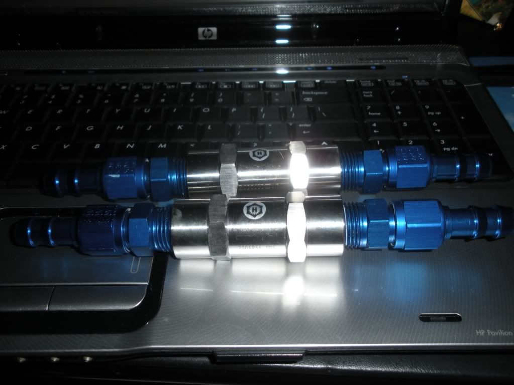
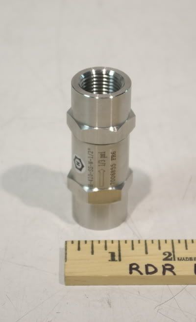
yup, its got one way check valves, but I dont know how necessary they are. the ports into the exhaust are at like a 45 degree angle, so it pretty much works all on venturi effect
Yep, put the evac tubes in the exhaust at a 45* angle. Atleast a few inches into the collectors IMO so there's no chance of reversion. On our jetboats we usually have them atleast 5-6" after the collectors.
LS1 Tech Stories
The Best V8 Stories One Small Block at Time

6 Common C5 Corvette Failures and What's Involved In Repairing Them
Pouria Savadkouei
Retro Modern Bandit Pontiac Trans AM Comes With Burt Reynolds' Autograph
Verdad Gallardo
Top 10 Greatest Cadillac V Series Performance Models Ever, Ranked
Pouria Savadkouei
Top 10 Most Powerful Chevy Trucks Ever Made!

Hennessey's New Supercharged Silverado ZR2 Has 700 HP
Verdad Gallardo
Coachbuilt N2A Anteros Is an LS2-Powered C6 Corvette In Italian Clothes
Verdad Gallardo
Awesome K5 Blazer Restomod Comes With C7 Corvette Power
Verdad Gallardo
10 Camaros You Should Never Buy

10 LS Engine Myths That Refuse to Die
Verdad Gallardo
PM me where to get sum of this.


I used to sell them. I dont any more but am looking to have them made again. I have seen a big push to have them offered again. I am working with two machine shops now to see what we can do.


Here is how I ran mine:


-10 AN between the valve covers with a -12 AN running to a Moroso breather. The 10 AN lines had bungs welded into the covers (I milled the covers to sink the bungs in flush) and the -12 AN is where the factory PCV port was (rear of driver's side cover) so the baffling is still in place. No discernible oil in the intake at 6-7 psi of boost, we'll see how it handles 15-18 this summer.
Oh, and FWIW, the fuel pressure regulator and return line have since been relocated to somewhere better.
edit: In more detail: