


PVC Catch can system.... Final conclusive answer
How much oil is collected in your guys catch cans? I've got no idea what to expect next year with the new shortblock (seeing 12-13psi D1SC). Do they fill up rather quickly? Is any oil needed between oil changes (2500-3000 miles)? If there is, would it be a bad idea to run a line from the bottom of the catch can(s) to the oil pan with a PCV valve in that line to allow oil to flow down at idle (or when car is off even), but not get pushed back up when at higher RPMs?
I'm thinking a -10 from each cover either into separate catch cans, or into one like the KYTP one (either way, a breather on can(s)). Then at the bottom of the can a drain back to the oil pan (like I said, with a checkvalve so crankcase pressure would not push oil UP this line). Would then use a PCV valve off of the LS6 valley cover into the manifold to draw a vacuum at idle, with an additional check valve so as not to pressurize the crankcase.
Nipple on throttle body would be capped..
TECH Resident
Joined: Jan 2007
Posts: 751
Likes: 0
From: Texas
There has to be a "Best Design" specific for NA, Centri FI, Turbo FI, KB-Maggie-etc., setups. I'm guessing it could possibly be a different design for each. With that in mind, I'm certain that would narrow down the "one design fits all" mentality that seems to be complicating this issue as I still have not seen a design that everybody agrees on. Can someone please post schematic design of "Best Centrifugal Supercharger Catch Can(s) Setup" 
Mine is simple.TB, intake, and valve cover ports plugged with LS6 valley cover with McMaster carr check valve part # 7775K52 to a AMW catch can and from there to the intake side of the turbo's. And a single metco breather on the passenger side valve cover. It is cheap and it works. The only definate answer is the one that works for you.

Pull IN the rear main seal? I have never heard of such a thing happening! So what happens w/ folks running the old belt driven vacuum pump? Are they adding air into the crankcase? Odd...just never heard of this being done. Do you know why the Krank Vent folks explicitly say NOT to vent to atmosphere (but actually want you to use a valve that allows one-way flow out of the crankcase, not in).
I appreciate the education...that's why I've been following this thread.
I appreciate the education...that's why I've been following this thread.
On the seals, yes! If you have no vacume relief, the seals can & do get pulled in & then not only do you have an oil leak at pressure, but a direct unfiltered entry of water, dirt, sand, dust, etc. directly into the crankcase (as some very ignorant folks have done by plugging everything off & just running open hoses down from each valve cover to near the ground...CRAZY, but we see a tuner doing it all the time). Also, i9f to much vacume is pulled (any more than 12-14 inches) wil start to pull the oil film off the wrist pins & main journals resulting in failure. On a street driven engine...especially FI applications, the system has to be designed similar to some of the contributors have done already....with an effective catch can that has proven to work.
Now on the vac pump systems, we run belt driven vacume pumps on all of our alky fueled race motors for several reasons, one being better ring seal (we build them w/low tension rings to facilitate this) but also to remove the massive amounts of moisture the methanol draws in and to evac the un-burnt meth that gets past the rings (all motors have some leakage). To avoid pulling to much vac we use an adjustable relief valve in the opposite valve cover that we pull from & a simple baffled catch can w/breather to trap the water & oil vapor so it does not get expelled onto the track or tires. This setup is far from practical on the street as we have to empty the cans evry 2-3 runs, and we are not concerned with the dust drawn in as we are not running on a dirty street, just a 1/4 mile down a treated track, and we change oil every few races. Last, we freshen each season so t5he extra wear from dirt is all figured in (we run a screen in the scoop to keep the larger pebbles out since a filter affects consistancy & power to much).
Bottom line is, the crankcase needs no unfiltered access, must have a filtered fresh air source, must route the system so it flows through the crankcase (not just in & out one valve cover), it must have check valve/s in the proper places to prevent boost blowing back into the crankcase, must also have an idle/low RPM non-boost source of vacume (intake manifold) with check valve/s (PCV valves) and a proven good effective catch can designed to effectivly trap & remove the oil mist/vapors.
We sell universal kits for NA applications, but it appears we need to offer a FI specific system as well.
TECH Resident
Joined: Jan 2007
Posts: 751
Likes: 0
From: Texas
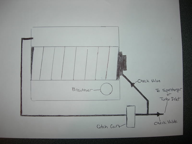
I think this might work. Cap off all ports other than ones used. LS6 valley port through check valve (to block boost) to one leg a "T" in front of CC. Driver side valve cover port (factory PCV line) into back of CC. From "T" in front of CC to Check valve then on to intake side of Supercharger or Turbo. The system will either "choose" the strongest vacuum (or maybe combined but I think the check valves will only allow one line to pull) source (intake manifold under deceleration/supercharger-turbo under boost) to pull crankcase vapors through CC. Fresh air is introduced into the system through a breather on oil filler cap. The check valves can either be the McMaster Carr units or the Krank Vent units.
It seems to me that with this system you will always have vacuum pulling fresh air into the engine that should evacuate harmful oil vapors collecting into the CC before it gets re-introduced into your engine. If anybody sees that this will not work please punch some holes in it

LS1 Tech Stories
The Best V8 Stories One Small Block at Time

6 Common C5 Corvette Failures and What's Involved In Repairing Them
Pouria Savadkouei
Retro Modern Bandit Pontiac Trans AM Comes With Burt Reynolds' Autograph
Verdad Gallardo
Top 10 Greatest Cadillac V Series Performance Models Ever, Ranked
Pouria Savadkouei
Top 10 Most Powerful Chevy Trucks Ever Made!

Hennessey's New Supercharged Silverado ZR2 Has 700 HP
Verdad Gallardo
Coachbuilt N2A Anteros Is an LS2-Powered C6 Corvette In Italian Clothes
Verdad Gallardo
Awesome K5 Blazer Restomod Comes With C7 Corvette Power
Verdad Gallardo
10 Camaros You Should Never Buy

10 LS Engine Myths That Refuse to Die
Verdad Gallardo
I still think that MM is the best. I did it his way and after I turn off the car you can here the vac bleed off for awhile still. Works for him so its definetly good for me 

can you or someone post his? how well will the one that pulls vac thru the turbo intake then a filter on the other?
Try a search, if you can't find it than you aren't looking hard enough. Sorry, tired of diggin'tuff up all the time for people. More people have to learn how to search first, than ask questions IF they still aren't sure. I couldn't imagine how many threads I would have created if I simply asked every question with a thread.

This would seem to work well but I would use a vented catchcan off the passenger side VC so as not to get oil mist everywhere. I would also connect the rear ports of both VC's to the catch can.
The system looks to work well because it pulls vacuum when idling from the driver side VC without introducing oil into the intake with catch can; and pulls vacuum from the driver side VC when under boost by way of the line going to the turbo inlet. And because there is a checkvalve on the Intake, you are not pushing boost back into the engine. Like I said, I like it except I wouldn't run an open breather on the DS VC just because of the mess it makes. Yea, you would have to run two catch cans but it's worth it to have a PCV system for crusing around and to not have oil mist in your clean engine bay. Keeps those rings seated!

I think this might work. Cap off all ports other than ones used. LS6 valley port through check valve (to block boost) to one leg a "T" in front of CC. Driver side valve cover port (factory PCV line) into back of CC. From "T" in front of CC to Check valve then on to intake side of Supercharger or Turbo. The system will either "choose" the strongest vacuum (or maybe combined but I think the check valves will only allow one line to pull) source (intake manifold under deceleration/supercharger-turbo under boost) to pull crankcase vapors through CC. Fresh air is introduced into the system through a breather on oil filler cap. The check valves can either be the McMaster Carr units or the Krank Vent units.
It seems to me that with this system you will always have vacuum pulling fresh air into the engine that should evacuate harmful oil vapors collecting into the CC before it gets re-introduced into your engine. If anybody sees that this will not work please punch some holes in it
The system looks to work well because it pulls vacuum when idling from the driver side VC without introducing oil into the intake with catch can; and pulls vacuum from the driver side VC when under boost by way of the line going to the turbo inlet. And because there is a checkvalve on the Intake, you are not pushing boost back into the engine. Like I said, I like it except I wouldn't run an open breather on the DS VC just because of the mess it makes. Yea, you would have to run two catch cans but it's worth it to have a PCV system for crusing around and to not have oil mist in your clean engine bay. Keeps those rings seated!
I think this might work. Cap off all ports other than ones used. LS6 valley port through check valve (to block boost) to one leg a "T" in front of CC. Driver side valve cover port (factory PCV line) into back of CC. From "T" in front of CC to Check valve then on to intake side of Supercharger or Turbo. The system will either "choose" the strongest vacuum (or maybe combined but I think the check valves will only allow one line to pull) source (intake manifold under deceleration/supercharger-turbo under boost) to pull crankcase vapors through CC. Fresh air is introduced into the system through a breather on oil filler cap. The check valves can either be the McMaster Carr units or the Krank Vent units.
It seems to me that with this system you will always have vacuum pulling fresh air into the engine that should evacuate harmful oil vapors collecting into the CC before it gets re-introduced into your engine. If anybody sees that this will not work please punch some holes in it
Last edited by SStolen; Jun 23, 2008 at 03:12 AM.

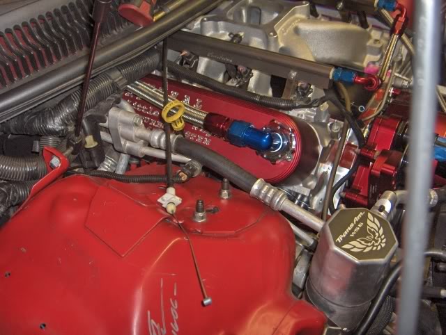
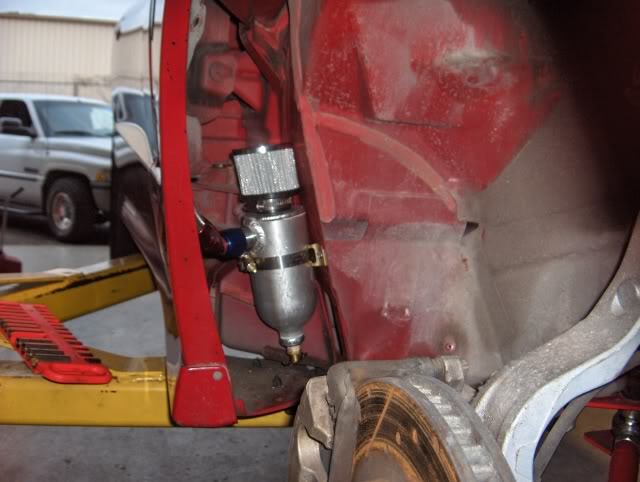
I will snap a couple of pictures of the system I am running.
It is a vented catch can with the vents off of the valve covers running into the can. I had a shop do this when I installed the D1.
I had been chasing down idle problems with my big non-blower friendly cam. After we did the vented system, my idle problems went away
It is very similar to what JMBLOWNWS6 is running except I have everything running into one big vented catch can.
Wow.
i just read everysingle page,..word for word, diagrahm for diagrahm. just when I think I have it all figured out, a new idea, or a new picture comes out. Some awesome info here, and some smart dudes. however,..you ******* lost me in the saturation.
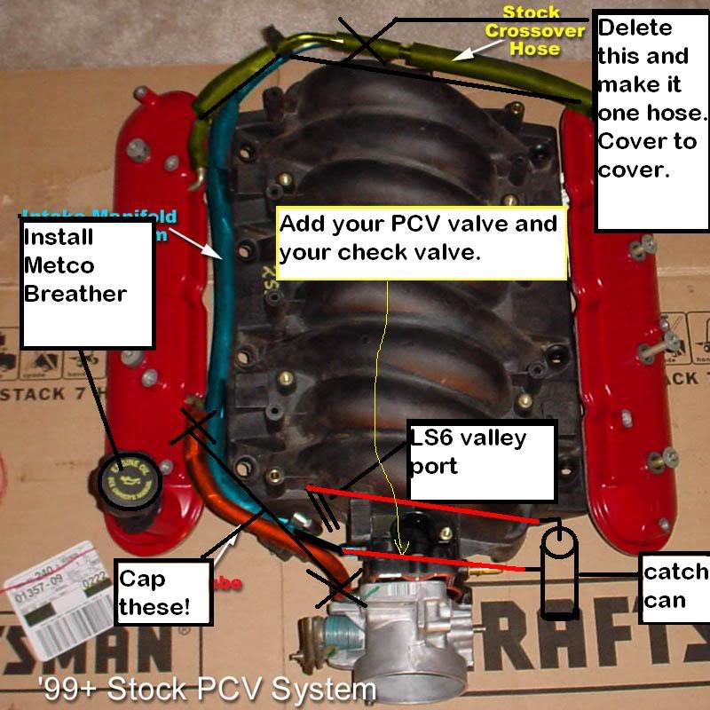
I am running a LS6 valley cover. I have stock valve covers. I have a TPiS cathcan with filter. From what I am gathering:
I should cap off everything, valley cover, tb port, everything. And I should run a line from BOTH VALVE COVERS, to my VENTED CATCH CAN(has filter)
http://www.tpis.com/catalogimages/LS1_Catch.jpg
or am I wrong?
I was running a blower setup, and I think I had the catch can attached the the LS6 valley cover, and the other outlet to the intake manifold. I had a check valve in between.
Now running a TT setup.
i just read everysingle page,..word for word, diagrahm for diagrahm. just when I think I have it all figured out, a new idea, or a new picture comes out. Some awesome info here, and some smart dudes. however,..you ******* lost me in the saturation.
I am running a LS6 valley cover. I have stock valve covers. I have a TPiS cathcan with filter. From what I am gathering:
I should cap off everything, valley cover, tb port, everything. And I should run a line from BOTH VALVE COVERS, to my VENTED CATCH CAN(has filter)
http://www.tpis.com/catalogimages/LS1_Catch.jpg
or am I wrong?
I was running a blower setup, and I think I had the catch can attached the the LS6 valley cover, and the other outlet to the intake manifold. I had a check valve in between.
Now running a TT setup.

Ls6/LS2-3 setup:


Dry-sump C6 Z06 setup:


Oil in the intake at 10,000 miles of street driving:

Forced induction setup:


I'll take some more detailed pics of the FI applications to show the entire system to clarify. Hundreds of these out there in use with the best possible results, and not having to sacrifice engine life to do it.
Dry-sump C6 Z06 setup:
Oil in the intake at 10,000 miles of street driving:
Forced induction setup:
I'll take some more detailed pics of the FI applications to show the entire system to clarify. Hundreds of these out there in use with the best possible results, and not having to sacrifice engine life to do it.