
a new catch can option from...home depot?
 07-05-2007 | 11:54 PM
#1

Thread Starter
TECH Fanatic
iTrader: (9)
Joined: Apr 2005
Posts: 1,395
Likes: 0
Received 0 Likes
on
0 Posts
From: ATL/Savannah Georgia
So i was searching for one of those husky air/oil separators for my PCV line and stumbled upon this:
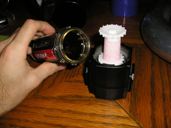

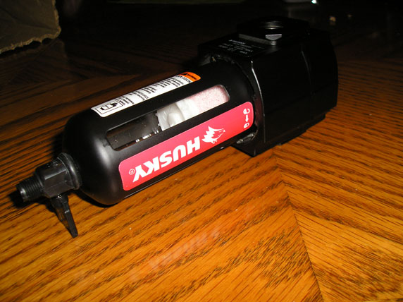
Its a larger version of the husky oil sep. It has two 3/8" openings. One inlet and one outlet. The canister easily disconnects but it still has a peacock valve on the bottom. So do you guys think this one would work as a regular catch can?
Here is how my PCV is setup:
-TB is plugged
-Intake > Mini Oil Sep > PCV > Check Valve > Pass. Rear Valve Port
-Front Pass valve cover and Driver side rear port merge together with a "T" hose barb and fit into the bigger husky unit which has a breather on the other port.
Heres my question:
-will that PCV setup work?
-is it ok having the 2 lines merge
-how big of a breather do I need on the husky unit because my 3" filter is a bit big.
so watcha think for $20?
07-06-2007 | 02:51 PM
#2

10 Second Club
iTrader: (14)
Joined: Dec 2005
Posts: 1,392
Likes: 0
Received 0 Likes
on
0 Posts
From: Central California
that setup looks good, and a big money saver!! i was debating on merging the two valvecover ports into one line that goes to the catchcan, but i figured 2 lines would flow more than 1, so I added the other one just because. i dont see why your setup wouldnt work though... its pretty similar to mine, and mine is working good so far!
one question...
which check valve are you using between the front valvecover port and the intake manifold? i am thinking of going that route instead of dealing with the STS switch to block the boost from entering the crankcase
one question...
which check valve are you using between the front valvecover port and the intake manifold? i am thinking of going that route instead of dealing with the STS switch to block the boost from entering the crankcase

 07-06-2007 | 11:21 PM
#4

I can't say it won't work, but make sure it can handle everything a car will throw at it, like high temps, large temp swings, vibration, getting washed, etc. before you use it. If it will handle all that, the piece looks like it will do the job.
If it fails - fire potential. Those are the stakes.
Jim
If it fails - fire potential. Those are the stakes.
Jim
Last edited by DeltaT; 07-08-2007 at 12:46 AM. Reason: typo
07-06-2007 | 11:41 PM
#5


I tried something similar several years ago: An air compressor air/oil separator. The engine oil and evironment ate it alive within a few weeks.
Not saying yours won't work, but mine was toast in a relatively short time.
Not saying yours won't work, but mine was toast in a relatively short time.
07-06-2007 | 11:53 PM
#6
After thinking about it, the one I ran had a metal body w/ a glass tube...and those temps can get high so MAKE SURE that if its plastic, it will be able to handle the temps thrown at it. I ran mine on a 03 Cobra for months w/o any problems what so ever.
Trending Topics
07-07-2007 | 03:12 AM
#8
TT-TECH Veteran
iTrader: (29)
Originally Posted by Sabre_Logos
I am using the same Husky oil/water separator on my car.


07-07-2007 | 03:29 AM
#9
Thread Starter
TECH Fanatic
iTrader: (9)
Joined: Apr 2005
Posts: 1,395
Likes: 0
Received 0 Likes
on
0 Posts
From: ATL/Savannah Georgia
sabre logos thats a nice looking install. Where is the outlet port running to off the can?
What do you guys think about things like T'ing the lines into the can and running the breather on the other side of it? Do I really need a big 2.5-3" breather or will a mini one work?
This is really pretty temporary (as in a week or two) because I'm working on machining my own can at home but I need something by next tuesday because the car will be up and running and getting tuned out of town.
Im also mounting it next to the battery away from most of the hot stuff. Hopefully this will work.
part # 7775k52 Brass Spring-Loaded Piston Check Valve 1/4" Nptf Dryseal Female Connections, Viton Seat
from mcmaster carr. Im going to mount everything in this order:
coming off intake manifold > oil sep > PCV > check valve > to rear pass port
do i really need that oil sep? seems like boost or vacuum would suck that oil. Do the STS "switches" have built in oil seperators?
What do you guys think about things like T'ing the lines into the can and running the breather on the other side of it? Do I really need a big 2.5-3" breather or will a mini one work?
This is really pretty temporary (as in a week or two) because I'm working on machining my own can at home but I need something by next tuesday because the car will be up and running and getting tuned out of town.
Im also mounting it next to the battery away from most of the hot stuff. Hopefully this will work.
Originally Posted by RooRnZ28
one question...
which check valve are you using between the front valvecover port and the intake manifold? i am thinking of going that route instead of dealing with the STS switch to block the boost from entering the crankcase
which check valve are you using between the front valvecover port and the intake manifold? i am thinking of going that route instead of dealing with the STS switch to block the boost from entering the crankcase
from mcmaster carr. Im going to mount everything in this order:
coming off intake manifold > oil sep > PCV > check valve > to rear pass port
do i really need that oil sep? seems like boost or vacuum would suck that oil. Do the STS "switches" have built in oil seperators?
Last edited by JAvenger007; 07-07-2007 at 04:29 AM.
07-07-2007 | 04:38 AM
#10
TT-TECH Veteran
iTrader: (29)
Well I really don't understand exactly how you are saying you are going to install it probably cause I am working night and I am Really tired, but I ran mine from the intake to the check valve and from the check valve to the catch can so that it pulls a vacum under non boost conditions and then the valve keeps the boost from blowing into the crank case. And I installed a single breather worked well and kept the oil out of the intake of course I think the best way is to have it hooked up to the intake of the turbo so that it pulls a vacum under boost conditions. Good luck I am sure you will figure out what works best for you.
Jeff
Jeff
07-07-2007 | 11:39 AM
#11

Teching In
Joined: Jan 2006
Posts: 11
Likes: 0
Received 0 Likes
on
0 Posts
From: Pacific Northwest
Inspector12, the car is my 94 Infiniti Q45 that is now packing a T76 Thumper. I've got a write up on my site but I don't know if it is cool to post the link on here so I'll just show you guys the pics. I installed the catch can on the fresh air intake hose for the original PCV intake.
From the catch can, the hose goes to the air filter. When the car is not in boost, the air will be drawn towards the engine thru the catch can and air filter. Under boost, the system operates in the other direction and any blow-by will be sucked in by the turbo thru the catch can.
This is the plastic hose barb that was installed on the filter.

A hole was drilled on the air filter and the plastic fitting glued on.


I ran a hose from the drain so that I don't have to remove the bottom of the catch can to empty it.

You can see the drain valve on the air/water separator in this pic.

From the catch can, the hose goes to the air filter. When the car is not in boost, the air will be drawn towards the engine thru the catch can and air filter. Under boost, the system operates in the other direction and any blow-by will be sucked in by the turbo thru the catch can.
This is the plastic hose barb that was installed on the filter.
A hole was drilled on the air filter and the plastic fitting glued on.
I ran a hose from the drain so that I don't have to remove the bottom of the catch can to empty it.
You can see the drain valve on the air/water separator in this pic.
Last edited by Sabre_Logos; 07-07-2007 at 11:45 AM.
07-07-2007 | 11:54 AM
#12
Teching In
Joined: Jan 2006
Posts: 11
Likes: 0
Received 0 Likes
on
0 Posts
From: Pacific Northwest
Originally Posted by JAvenger007
Where is the outlet port running to off the can?
 07-07-2007 | 10:29 PM
#15
TT-TECH Veteran
iTrader: (29)
Originally Posted by Sabre_Logos
Inspector12, the car is my 94 Infiniti Q45 that is now packing a T76 Thumper. I've got a write up on my site but I don't know if it is cool to post the link on here so I'll just show you guys the pics. I installed the catch can on the fresh air intake hose for the original PCV intake.
From the catch can, the hose goes to the air filter. When the car is not in boost, the air will be drawn towards the engine thru the catch can and air filter. Under boost, the system operates in the other direction and any blow-by will be sucked in by the turbo thru the catch can.
This is the plastic hose barb that was installed on the filter.
A hole was drilled on the air filter and the plastic fitting glued on.
I ran a hose from the drain so that I don't have to remove the bottom of the catch can to empty it.
You can see the drain valve on the air/water separator in this pic.
07-08-2007 | 12:48 AM
#16
Teching In
Joined: Jan 2006
Posts: 11
Likes: 0
Received 0 Likes
on
0 Posts
From: Pacific Northwest
Originally Posted by Inspector12
That explaines it Infinity and Nissan are basicly the same co.. I just reconized a few things. Is the 76 on the 3.5L or what? Looks good anyways.
Here are some pics:
VH45DE block with aftermarket sleeves bored out to 98mm. Not mine, belongs to gearhead in the UK.

Pentroof combustion chamber

Here's description from Road & Track's Guide to the Q45. Remember that this engine was designed somewhere in the late 80's and showed up in the first gen Q45 in the fall of 89.
 07-08-2007 | 10:06 AM
#17
TECH Senior Member
iTrader: (33)
Not sure if it was mentioned, but please note that the valve on the bottom will NOT hold vacuum. It has to be blocked off. I have been running this setup on my car for a little over a month with great results. The brass element seems to be much better (I use the Lowe's version).
Last edited by WS6FirebirdTA00; 07-08-2007 at 10:26 AM.
07-08-2007 | 11:33 AM
#19
Joined: Sep 2006
Posts: 405
Likes: 0
Received 0 Likes
on
0 Posts
From: P'cola, FL / Okc, OK
I have been following just about all the PCV threads trying to decide on the best set up for my vehicle, and still have a question about the routing of the hoses.
If you ran with the Husky way, how would you route the hoses from the back of the D/S valve cover, front pass. valve cover, intake, and TB. I know on almost all set ups you want to block the TB off. I've heard that using a T to connect the D/S rear cover and the P/S front together doesn't allow max. flow.
If you ran with the Husky way, how would you route the hoses from the back of the D/S valve cover, front pass. valve cover, intake, and TB. I know on almost all set ups you want to block the TB off. I've heard that using a T to connect the D/S rear cover and the P/S front together doesn't allow max. flow.
Last edited by OreoLt1; 07-08-2007 at 03:49 PM.