

Gen 5 Wiring Schematics & Cluster Pinouts
 02-01-2013, 05:24 AM
#1
Teching In
Thread Starter
iTrader: (1)

Join Date: May 2003
Location: New York State -The Tax State-
Posts: 28
Likes: 0
Received 0 Likes
on
0 Posts

Hi all,
I wasn't sure where to put this post, but it would seem this isn't "electronics", in the typical sense.
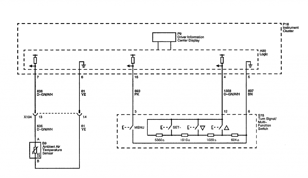
Is there anyone who can get me started with pinouts for the 2010-2013 Cluster, BCM, PCM?
Right now I have a few clusters on the bench, and I'm trying to get started shaking out some design ideas. Any help, info, links, pdf's, emails, would be greatly appreciated.
Thanks!
 <-Did that
I wasn't sure where to put this post, but it would seem this isn't "electronics", in the typical sense.
Is there anyone who can get me started with pinouts for the 2010-2013 Cluster, BCM, PCM?
Right now I have a few clusters on the bench, and I'm trying to get started shaking out some design ideas. Any help, info, links, pdf's, emails, would be greatly appreciated.
Thanks!
<-Did that 
 02-04-2013, 05:33 PM
#5
Teching In
Thread Starter
iTrader: (1)
Join Date: May 2003
Location: New York State -The Tax State-
Posts: 28
Likes: 0
Received 0 Likes
on
0 Posts
Gun,
Thanks. I usually just order said manuals through Helm directly. I was hoping I'd find info from the boards, so wouldnt have to wait. . Nothing seems to be posted thus far. I did check out Camaro5 as well.
Thanks. I usually just order said manuals through Helm directly. I was hoping I'd find info from the boards, so wouldnt have to wait.
. Nothing seems to be posted thus far. I did check out Camaro5 as well.
02-04-2013, 09:08 PM
#6
TECH Enthusiast
Join Date: Nov 2004
Location: Tampa FL
Posts: 714
Likes: 0
Received 0 Likes
on
0 Posts
Damn Chevrolet doesn't even have them for sale at their parts counter?
Trending Topics
02-05-2013, 09:34 AM
#9
Teching In
Thread Starter
iTrader: (1)
Join Date: May 2003
Location: New York State -The Tax State-
Posts: 28
Likes: 0
Received 0 Likes
on
0 Posts
Actually, I think the guy on ebay is excessive. Given the price of textbooks in the USA (@ $240-285), $200 isn't all that bad. lol Especially given the smaller customer base. But, price of such things is perhaps best for another thread. BTW "international" versions of many books (99.99 % same pics and text) are typically $25-$55. Price discrimination, absolutely.
I'm wondering if anyone knows if there is content in the paper, which isn't present in the Helm DVD.
I did manage to find someone who knew essential pins for me, for cluster Batt, IGN, and GND. They work. I'd like do more homework, and find out a good deal more. At least I have a starting point.
I'm wondering if anyone knows if there is content in the paper, which isn't present in the Helm DVD.
I did manage to find someone who knew essential pins for me, for cluster Batt, IGN, and GND. They work. I'd like do more homework, and find out a good deal more. At least I have a starting point.
 02-05-2013, 09:50 AM
#11
Teching In
Thread Starter
iTrader: (1)
Join Date: May 2003
Location: New York State -The Tax State-
Posts: 28
Likes: 0
Received 0 Likes
on
0 Posts
Mrgoodwrench3,
Wow! Thank you very much!
OK, I have one broken cluster, and one brand new. I experimented on the broken one, and quickly realized none of the circuits for illumination act as I anticipated. I got the ID for pins, for Batt, GND, and IGN to cluster. It illuminated the broken one. Cool. I fabbed up a 20 pin cable and powered up the new virgin one.
On the new cluster, turns on, illuminates brightly for 4 secs and goes back to a much dimmer brightness setting (also cycles through a long list of things I should be checking, including 4WD!) lol. It states it needs to be programmed. (flashed).
Can you find an input for illumination brightness setting, variable resistor? Or is that logically controlled through the BCM?
02-05-2013, 10:42 AM
#12
TECH Enthusiast
Join Date: Jan 2010
Location: Irvine, CA.
Posts: 544
Likes: 0
Received 0 Likes
on
0 Posts
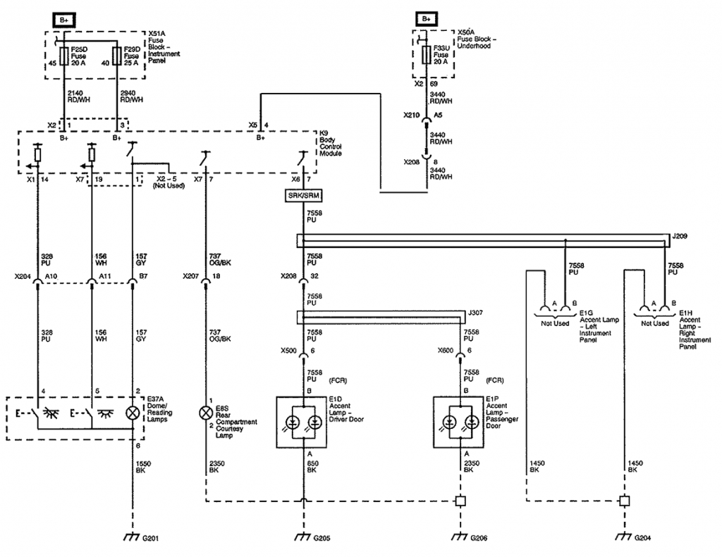
The body control module (BCM) supplies a voltage reference to the dimmer switch, which is part of the headlamp switch. When the dimmer switch is placed in a desired brightness position, reference voltage is applied through the dimmer switch to the BCM. The BCM interprets this voltage signal, then applies a variable voltage through the LED backlight lamp control circuit.
When the ignition switch is turned to the RUN position, the radio VF display turns ON at maximum brightness. When the park lamps are ON, all incandescent and LED back lighting turn ON at the dimming level indicated by the instrument panel (I/P) dimmer switch. At the same time all VF displays dim to match the indicated dimming level. The panel dimmer switch potentiometer is an input to the body control module (BCM). When the driver selects a dimming setting by moving the I/P dimming switch potentiometer, all incandescent back lighting lamps are provided with a specific voltage. When the I/P dimmer switch is moved from MIN to MAX, all VF displays, as well as all incandescent back lighting respond from minimum intensity to maximum brightness in response to the I/P dimmer switch.
The left and right front door switch illumination is controlled, receives voltage, and ground from the driver door switch and passenger switch respectively. The radio is also a GMLAN module and has full control of its illumination. The BCM, door switches, and radio communicate through GMLAN serial data for the lamp illumination commands.
The various switches, HVAC control assembly, and the PRNDL lamps receive voltage and are controlled by the BCM on the I/P lamps dimming control circuit.
The following indicators receive voltage from the BCM and are controlled by ground from a switch or from various modules:
Radio
HVAC control assembly
Instrument panel cluster (IPC)
Driver information center (DIC)
Headlamp and panel dimmer switch
The indicators receive voltage from the BCM on the LED dimming circuit. Control for the indicators is from the various modules or switches. Voltage for the LED dimming supply circuit, instrument panel lamps dimming control circuit and the instrument panel lamps dimming supply circuit is from the BCM.
02-06-2013, 04:01 PM
#14
Teching In
Thread Starter
iTrader: (1)
Join Date: May 2003
Location: New York State -The Tax State-
Posts: 28
Likes: 0
Received 0 Likes
on
0 Posts
MrGoodwrench,
Thank you! I suspected illumination might go that way. From the diagrams, it looks like a switchbox for the digital display can be fabbed pretty easy, but alas, GMLAN is controlling illumination. Perhaps Ill need to wire up half of a Camaro on my bench if I want to control brightness levels, or drive gauges. lol.

For the moment I got them powered up and illuminated. One cluster which has not been flashed yet, lights up bright, for 4 secs, then dims down to a low setting. The second cluster, doesn't do this, rather it stays full brightness. Perhaps it recalls it's last brightness setting.
Thank you! I suspected illumination might go that way. From the diagrams, it looks like a switchbox for the digital display can be fabbed pretty easy, but alas, GMLAN is controlling illumination. Perhaps Ill need to wire up half of a Camaro on my bench if I want to control brightness levels, or drive gauges. lol.
For the moment I got them powered up and illuminated. One cluster which has not been flashed yet, lights up bright, for 4 secs, then dims down to a low setting. The second cluster, doesn't do this, rather it stays full brightness. Perhaps it recalls it's last brightness setting.
