Write up: How to make your own passenger window fix!
 05-23-2009, 01:52 AM
#1
As most of you know, us F-Body guys have been dealing with window motors going out, and usually a PITA to deal with. And im sure most of you have heard about the "fix" offered by a vendor who is no longer a sponsor on LS1Tech. This fix is actually fairly easy to do yourself, as long as you have some experience with wiring (crimping, etc. nothing too difficult). I took the liberty of making a write up to save you all some headaches (and money), so here you go.
The reason the passenger window motors on these cars tend to be such a problem is due to poor design. The window motors are rated at 12 volts, yet most of these motors never get more then 9 volts. Over time, the lack of current supplied to the motor will stress it out and cause it to eventually die. Typically, you will start to notice that the window will slow down dramatically as it reaches the top of the track, and over time, the motor will stop, and go up another inch after a minute or so. Eventually, the window will not go up or down at all.
The reason for this is because the passenger window motor is "piggybacked" onto the driver side switch, so while the driver side window will usually get a full 12 volts, the passenger side motor has to draw current from lots of wiring that is already not giving a full signal. The only time the drivers side window circuit will lack current is when you lower both windows at once. The fix is rather simple, just use a relay to supply a full 12 volts to the passenger window motor at all times.
To make your own window fix you will need the following:
Two 5-pin automotive relays, usually they are rated at 30 or 40 amps. (The pins need to be labeled 87, 87a, 86, 85, 30)
Spool of 12AWG wire (not sure exactly how much you will need, but its cheaper to buy a small spool. If I had to guess id say about 30ft, probably less).
A pack or two of butt connectors, a pack or two of female spade connectors for the relays, and 2 circular butt connectors to ground your connection (make sure they all fit 12AWG wiring).
Wire crimps/cutters
Some zip ties or velcro depending on how you want to mount the relay.
Electric tape (colored tape comes in handy to label your wires).
Thats about all I can think of at the moment, if I think of anything else I will be sure to add
Now on to the actual write up:
Start off removing your PCM bracket, which is held down by 2 10mm bolts right in front of the connectors (you dont need to remove the connectors to the PCM, but if you need to its just 2 9/32 bolts and they come off). Depress the two tabs on either side of the PCM and it will just pop out. Sometimes pulling it out of the way requires some finesse, youll see what I mean. There is a grommet behind the PCM that is perfect to run your power wires through. You can snake them through with a coat hanger, but 12awg is pretty firm so I just pushed mine through. You will need to remove the panel under the glove box, which is held by two plastic push-pin style hold downs. Just use a flat head screwdriver and/or pliers to pop them off. There may be some 9/32 bolts in there too, just pull them out, and finally there is a metal tab towards to back of the panel that you can remove but just sliding the metal off the bolt its attached to and the whole panel will pop off. Then go ahead and remove the panel the runs along the floorboard just to the right of the passenger seat, its held on there by a few phillips head screws, and that whole panel shop pop off.
Now that you have done all that, you will see lots of exposed wiring, and you will need to find to two rather thick brown and blue wires in there. Cut those wires and strip off the ends. The wire coming out of the door grommet goes straight to the motor.
Heres a diagram I made that will show you exactly how you need to wire everything up.

The diagram is pretty self explanatory, just attach all your wiring to the relays with the spade connectors. For the grounds, you can splice the wires coming off pins 85 and 87a together and go from there to your ground. A good ground location is the bolt just above where you see all the wiring running under your dash, it already has a ground attached to it. Just attach your circular connectors to ends of your ground wires and bolt them in with that existing ground. A good place to mount your relays is the little plastic pocket near the kick panel, you can zip tie or velcro the relays in there so they dont get bumped around. With everything put back together, none of the wiring will be visible.
Enjoy! If I left anything out I will absolutely come back and add it. Feel free to ask any questions.
The reason the passenger window motors on these cars tend to be such a problem is due to poor design. The window motors are rated at 12 volts, yet most of these motors never get more then 9 volts. Over time, the lack of current supplied to the motor will stress it out and cause it to eventually die. Typically, you will start to notice that the window will slow down dramatically as it reaches the top of the track, and over time, the motor will stop, and go up another inch after a minute or so. Eventually, the window will not go up or down at all.
The reason for this is because the passenger window motor is "piggybacked" onto the driver side switch, so while the driver side window will usually get a full 12 volts, the passenger side motor has to draw current from lots of wiring that is already not giving a full signal. The only time the drivers side window circuit will lack current is when you lower both windows at once. The fix is rather simple, just use a relay to supply a full 12 volts to the passenger window motor at all times.
To make your own window fix you will need the following:
Two 5-pin automotive relays, usually they are rated at 30 or 40 amps. (The pins need to be labeled 87, 87a, 86, 85, 30)
Spool of 12AWG wire (not sure exactly how much you will need, but its cheaper to buy a small spool. If I had to guess id say about 30ft, probably less).
A pack or two of butt connectors, a pack or two of female spade connectors for the relays, and 2 circular butt connectors to ground your connection (make sure they all fit 12AWG wiring).
Wire crimps/cutters
Some zip ties or velcro depending on how you want to mount the relay.
Electric tape (colored tape comes in handy to label your wires).
Thats about all I can think of at the moment, if I think of anything else I will be sure to add
Now on to the actual write up:
Start off removing your PCM bracket, which is held down by 2 10mm bolts right in front of the connectors (you dont need to remove the connectors to the PCM, but if you need to its just 2 9/32 bolts and they come off). Depress the two tabs on either side of the PCM and it will just pop out. Sometimes pulling it out of the way requires some finesse, youll see what I mean. There is a grommet behind the PCM that is perfect to run your power wires through. You can snake them through with a coat hanger, but 12awg is pretty firm so I just pushed mine through. You will need to remove the panel under the glove box, which is held by two plastic push-pin style hold downs. Just use a flat head screwdriver and/or pliers to pop them off. There may be some 9/32 bolts in there too, just pull them out, and finally there is a metal tab towards to back of the panel that you can remove but just sliding the metal off the bolt its attached to and the whole panel will pop off. Then go ahead and remove the panel the runs along the floorboard just to the right of the passenger seat, its held on there by a few phillips head screws, and that whole panel shop pop off.
Now that you have done all that, you will see lots of exposed wiring, and you will need to find to two rather thick brown and blue wires in there. Cut those wires and strip off the ends. The wire coming out of the door grommet goes straight to the motor.
Heres a diagram I made that will show you exactly how you need to wire everything up.
The diagram is pretty self explanatory, just attach all your wiring to the relays with the spade connectors. For the grounds, you can splice the wires coming off pins 85 and 87a together and go from there to your ground. A good ground location is the bolt just above where you see all the wiring running under your dash, it already has a ground attached to it. Just attach your circular connectors to ends of your ground wires and bolt them in with that existing ground. A good place to mount your relays is the little plastic pocket near the kick panel, you can zip tie or velcro the relays in there so they dont get bumped around. With everything put back together, none of the wiring will be visible.
Enjoy! If I left anything out I will absolutely come back and add it. Feel free to ask any questions.

 05-23-2009, 03:19 PM
#7
TECH Fanatic
iTrader: (9)

Join Date: Nov 2006
Location: Fresno, California
Posts: 1,985
Likes: 0
Received 0 Likes
on
0 Posts

Ok so i just read through all this and Im straight up till the wiring diagram. Where exactly do you hook up you for your power source? Your not just coming off the battery are you?
Trending Topics
05-23-2009, 10:10 PM
#11
TECH Fanatic
iTrader: (9)
Join Date: Nov 2006
Location: Fresno, California
Posts: 1,985
Likes: 0
Received 0 Likes
on
0 Posts
Hell I might end up just getting 2 of the autotrix kits one for both windows.
OP where are you tapping in for power?
05-24-2009, 12:29 AM
#12
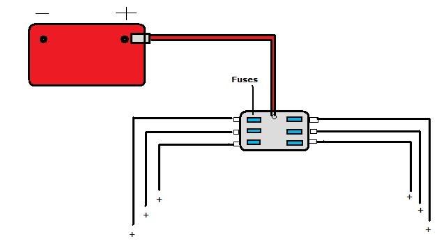
Sorry guys your right, I didnt make the power side of it clear. You need to tap in right at the positive side of the battery to get the highest possible voltage supply. Im actually running a separate fuse panel right off the battery, which takes a single input and distributes power through 6 slots which are all protected by fuses. You can also tap in right at the positive battery terminal using those butt connectors with the large hole at the end, you just need to use a fusible link. You can use a fuse rated at 30amps, that should be fine.
Yes you can buy the kit from autotrix, but you can make this kit for about half the price and have the pride of doing it yourself.
Yes you can buy the kit from autotrix, but you can make this kit for about half the price and have the pride of doing it yourself.
05-24-2009, 12:36 AM
#13
Id say if you have to change the window motor on the driver side, you might as well do this mod and save yourself some headaches.
05-24-2009, 12:36 AM
#14
TECH Fanatic
iTrader: (9)
Join Date: Nov 2006
Location: Fresno, California
Posts: 1,985
Likes: 0
Received 0 Likes
on
0 Posts
Sorry guys your right, I didnt make the power side of it clear. You need to tap in right at the positive side of the battery to get the highest possible voltage supply. Im actually running a separate fuse panel right off the battery, which takes a single input and distributes power through 6 slots which are all protected by fuses. You can also tap in right at the positive battery terminal using those butt connectors with the large hole at the end, you just need to use a fusible link. You can use a fuse rated at 30amps, that should be fine.
Yes you can buy the kit from autotrix, but you can make this kit for about half the price and have the pride of doing it yourself.
Yes you can buy the kit from autotrix, but you can make this kit for about half the price and have the pride of doing it yourself.
05-24-2009, 03:46 AM
#15
I got one from Autozone, I believe it was made by Bussman and cost about $8. I already had it in there because im running relays for my headlights and some other stuff, heres a diagram of the fuse panel:
Heres a picture of the type of fuse panel your looking for:
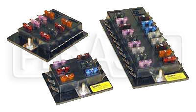
I used a short battery cable to attach to fuse panel to the battery, and from there you have tabs that connect to your wire via some spade connectors, comes in handy for mods in the future which is why I got it. Its probably an extra $10 to go with this setup but its worth it to me because I do alot of wiring, so that up to you.
Heres a picture of the type of fuse panel your looking for:
I used a short battery cable to attach to fuse panel to the battery, and from there you have tabs that connect to your wire via some spade connectors, comes in handy for mods in the future which is why I got it. Its probably an extra $10 to go with this setup but its worth it to me because I do alot of wiring, so that up to you.
 06-14-2009, 08:19 PM
#19
Has anyone actually done this and followed it exactly?
I ask because I'm about 99% sure there is something wrong with the wiring diagram in regards to the relay making the window go down (blue wires). When wired exactly as shown, as soon as I put the inline fuse in, the relay clicks and the window rolls itself up without any input from either switch (drivers door or pass door).
I'm in the process of troubleshooting right now, as I was doing this and taking pictures to make a detailed, step by step write-up.
The other thing is that a 30 amp fuse, while it would work, is bigger than necessary. The window motor only draws 15 amps of current during use, so I would go with a 20 amp. I will post back when I get this figured out...
06-15-2009, 05:38 AM
#20
Your positive wire coming from the battery should be connected to pin 87. Pin 86 is your signal switch, unless the switch is triggered it wont be supplying any voltage, and therefore wont switch open the relay to put the window down. This is the exact setup in my car and it works. Did you double check your connections? Let me know.
Has anyone else tried this? Let me know your results please.
Has anyone else tried this? Let me know your results please.