

My catch can routing ok?


 05-01-2012, 04:17 PM
#442
On The Tree
iTrader: (6)

Join Date: Jun 2007
Location: Leoma, TN
Posts: 197
Likes: 0
Received 0 Likes
on
0 Posts

 [/QUOTE]
I'm using the GMMG valve covers and was wondering how others are tapping into them to run to the TB? I'm just going with the simple diagram like above. Is drilling and tapping the valve cover the only way or is there a filler cap with a port or another way of running this?
05-01-2012, 06:05 PM
#443
I'm using the GMMG valve covers and was wondering how others are tapping into them to run to the TB? I'm just going with the simple diagram like above. Is drilling and tapping the valve cover the only way or is there a filler cap with a port or another way of running this?[/QUOTE]
CHeck this out
http://mtiracing.com/Purchase/1998-2...r-to-10-2.html
CHeck this out
http://mtiracing.com/Purchase/1998-2...r-to-10-2.html
05-01-2012, 11:49 PM
#444
I'm using the GMMG valve covers and was wondering how others are tapping into them to run to the TB? I'm just going with the simple diagram like above. Is drilling and tapping the valve cover the only way or is there a filler cap with a port or another way of running this?[/QUOTE]
Google: PCV Valve Cover Breather
Jegs an Summit both a a large selection.
I have a Earls #3434114 on mine; works great(remove the PCV for the fresh air).
Google: PCV Valve Cover Breather
Jegs an Summit both a a large selection.
I have a Earls #3434114 on mine; works great(remove the PCV for the fresh air).
 06-03-2012, 05:09 PM
#446

Many thanks to all for the info here. As a means of thanks I wanted to pass this on to you. I have been using these on my cars including my race car for several years now with great success.
The MAN Provent 200 oil separating catch can.
These are cyclonic separators like a Dyson vacuum cleaner. water and crud is separated and caught in the filter and central catch area. Oil vapor condenses outside and runs to the bottom chamber.
There is an adjustable vacuum vent to control internal vacuum
The oil drain can either be closed with a tap, or by adding the check valve it can be plumbed back into the oil pan above the ol level line to automaticcly return to the oil sump.
The filter is removable by taking the screw top off, and can be washed with soap and water.
They retail for $150 to $200 and were originally developed for big stationary diesel engines.
Available here and other places I am sure http://www.034motorsport.com/engine-...0-p-20193.html
The following users liked this post:
Homer_Simpson (08-07-2023)
06-07-2012, 07:44 PM
#448
Teching In
Join Date: Nov 2009
Location: Texas
Posts: 19
Likes: 0
Received 0 Likes
on
0 Posts
Amazing job Aaron!! After going through the thread, most of my questions were answered, but I was surprised to see that one wasn't brought up...
My intent is a dual Catch Can setup. I am however running very high boost, understand that a vacuum pump can drastically improve ring seal. How do I connect the vacuum pump into this setup?
This will be for an LTX motor, but if you wanted to draw a diagram, leave it on an LS engine for your ease. Thanks for any help!!
06-08-2012, 11:36 AM
#449

Many thanks to all for the info here. As a means of thanks I wanted to pass this on to you. I have been using these on my cars including my race car for several years now with great success.
The MAN Provent 200 oil separating catch can.
These are cyclonic separators like a Dyson vacuum cleaner. water and crud is separated and caught in the filter and central catch area. Oil vapor condenses outside and runs to the bottom chamber.
There is an adjustable vacuum vent to control internal vacuum
The oil drain can either be closed with a tap, or by adding the check valve it can be plumbed back into the oil pan above the ol level line to automaticcly return to the oil sump.
The filter is removable by taking the screw top off, and can be washed with soap and water.
They retail for $150 to $200 and were originally developed for big stationary diesel engines.
Available here and other places I am sure http://www.034motorsport.com/engine-...0-p-20193.html
06-08-2012, 11:39 AM
#450
Amazing job Aaron!! After going through the thread, most of my questions were answered, but I was surprised to see that one wasn't brought up...
My intent is a dual Catch Can setup. I am however running very high boost, understand that a vacuum pump can drastically improve ring seal. How do I connect the vacuum pump into this setup?
This will be for an LTX motor, but if you wanted to draw a diagram, leave it on an LS engine for your ease. Thanks for any help!!
My intent is a dual Catch Can setup. I am however running very high boost, understand that a vacuum pump can drastically improve ring seal. How do I connect the vacuum pump into this setup?
This will be for an LTX motor, but if you wanted to draw a diagram, leave it on an LS engine for your ease. Thanks for any help!!
Aaron
06-08-2012, 04:06 PM
#451
Teching In
Join Date: Nov 2009
Location: Texas
Posts: 19
Likes: 0
Received 0 Likes
on
0 Posts
I don't want to confuse anybody here, so if you want to PM me that would be fine. Thanks again for the knowledge and help!
Ben
06-11-2012, 10:38 AM
#452
Morning,
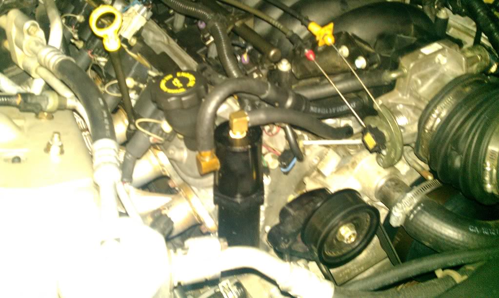
I am in the process of setting up the Provent on my LS powered Audi, this is the first time I have used one on an LS so I am working out the fittings etc. Audi's have 3/4 ports so its easy.
I typically use these brass PEX couplers from Home Depot etc, add a bead of epoxy and gently tap it in and you are done (note mine are not tapped in yet)
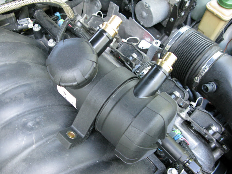
Location in the bay:


Space is extremely tight in here so finding room for things is hard. I will plumb the provent as a dirty side initially, I am wondering about also plumbing in the clean side as a single can as the provent has vacuum control etc built into it.
I know it is not Ideal though and most likely will need to make a little clean side can too.
Note the clear lines are temporary to get the car up and running, also note the amount of oil in the clear lines on the 'clean' side which is not really clean at all.
H
I am in the process of setting up the Provent on my LS powered Audi, this is the first time I have used one on an LS so I am working out the fittings etc. Audi's have 3/4 ports so its easy.
I typically use these brass PEX couplers from Home Depot etc, add a bead of epoxy and gently tap it in and you are done
(note mine are not tapped in yet)Location in the bay:
Space is extremely tight in here so finding room for things is hard. I will plumb the provent as a dirty side initially, I am wondering about also plumbing in the clean side as a single can as the provent has vacuum control etc built into it.
I know it is not Ideal though and most likely will need to make a little clean side can too.
Note the clear lines are temporary to get the car up and running, also note the amount of oil in the clear lines on the 'clean' side which is not really clean at all.
H
Last edited by timmmy; 06-11-2012 at 11:04 AM.
06-12-2012, 08:36 AM
#453
12 Second Club
iTrader: (3)
Join Date: Apr 2004
Location: Grand Rapids, Michigan
Posts: 1,512
Likes: 0
Received 2 Likes
on
2 Posts
Here's the problem with a catch can. When is most of the blow-by produced? Under WOT. When DON'T you have any vacuum to pull oil vapor out of the crankcase and thru a traditional catch can? Under WOT. The normal routing can and will have vapor traveling backwards up the "fresh air supply" line and into the TB bypassing the catch can. They do something but aren't going to keep oil out of the manifold.
I tried a more elaborate system that was pretty cheap to put together and has worked better. It uses a valve cover breather to eliminate that path back to the TB and also uses an oil cooler to cool and condense vapors as well as an extremely large can with a lot of media to catch the droplets. It is mounted out of sight in front of the wheel on my '04 GTO. I later substituted copper "Chore Boys" for the media. Here is the unit for comparison next to an oil separator from Home Depot.
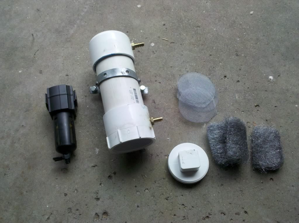
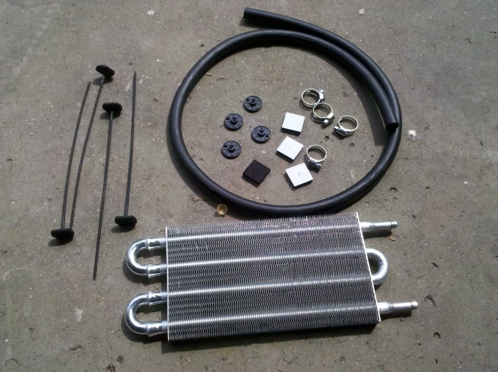
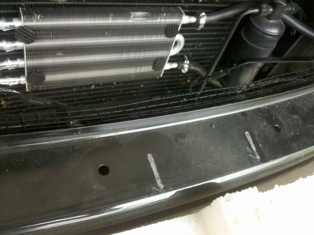
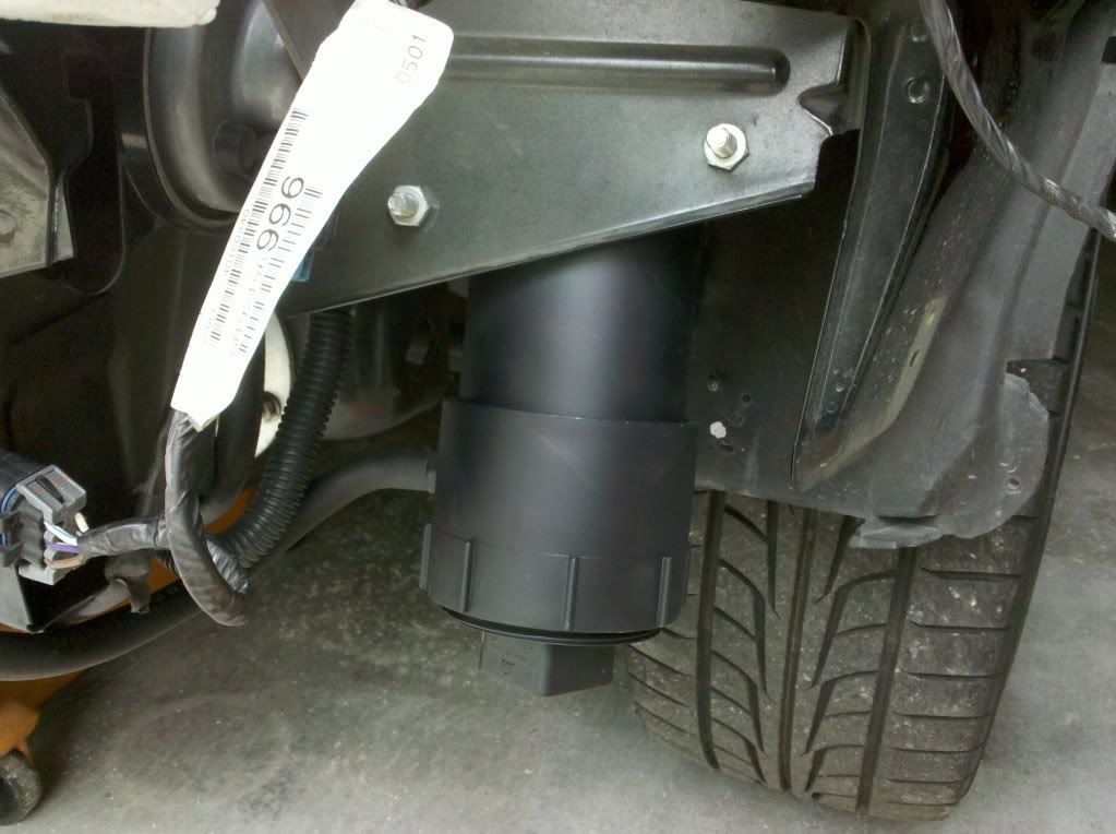
I tried a more elaborate system that was pretty cheap to put together and has worked better. It uses a valve cover breather to eliminate that path back to the TB and also uses an oil cooler to cool and condense vapors as well as an extremely large can with a lot of media to catch the droplets. It is mounted out of sight in front of the wheel on my '04 GTO. I later substituted copper "Chore Boys" for the media. Here is the unit for comparison next to an oil separator from Home Depot.
06-12-2012, 09:41 AM
#454

Wondered why this thread kept popping up. Wow, some nice stuff being shared here. Those oil separators are pretty cool. Only concern I'd have w/ the Home Depot version would be steel wool peices getting by the screens & into the intake. Just an observation. The concept is excellent. Thanks guys for the info.
Damn! @ this rate there will be small oil recycling plants under our hoods, lol.
Damn! @ this rate there will be small oil recycling plants under our hoods, lol.

 06-28-2012, 08:07 PM
#459
Launching!

Hello all,
I just installed the Mike Norris catch can on my 1998 z28 with stock intake manifold , pcv etc. I've had it on for about 1 day and it has already caught some dribbles of oil
My confusion lies in some of the diagrams showing the rear passenger port plugged off and some show it left untouched. Which way is correct? I don't really want to mess with it if the way I have it is correct...
07-18-2012, 05:24 AM
#460
