

My catch can routing ok?
 10-19-2013, 04:19 AM
#521


Firstly I would like to add what others have already said and that's a BIG thank you for this post and all of its information.
My only comment would be if the pictures/Diagrams by 405HP Z06 could be separate from the rest of the text as understandably there are requests for clarification on designs scattered throughout the post. I think separating this would help and it would also mean that any additional diagrams could be added should anyone have a setup not already covered.
Great thread
 10-19-2013, 07:10 PM
#522

I I agree this thread rocks tons of info here hard to keep up but if anyone has any questions about what my setup does specifically please see the link in my signature or go ahead with the PM it doesn't work like everyone elses on the surface. 
11-03-2013, 07:33 AM
#523
Teching In

Join Date: Feb 2013
Location: Hampshire, UK
Posts: 3
Likes: 0
Received 0 Likes
on
0 Posts
Wow..... Awesome thread.....
What PSI will a 04 LS6 PCV valve cope with before it lets pressure back in to the crank???
I'm running 8-9 psi at the moment. Could I use a second GM PCV valve inline as a Check valve after the catch can???
Thanks.
What PSI will a 04 LS6 PCV valve cope with before it lets pressure back in to the crank???
I'm running 8-9 psi at the moment. Could I use a second GM PCV valve inline as a Check valve after the catch can???
Thanks.
11-06-2013, 09:52 PM
#524
On The Tree
Join Date: Mar 2009
Location: athens tx
Posts: 102
Likes: 0
Received 0 Likes
on
0 Posts
im running this setup (ls1 valley cover) and i was just wondering what to do with the hose that i took off from the rear of the passenger valve cover? do i just cap it off as well? or leave it open? sorry for the question and thanks for the help.
11-07-2013, 05:36 PM
#527
Staging Lane

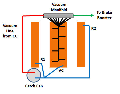
Sorry guys, but I still not exactly sure about this. I am running an 8ITB induction. I am not allowed to have a vent to atmosphere due to our emission laws.
I was planning on joining together the two rocker cover vents, also the valley cover vent and taking them into the catch can. Then take the CC to the end of the manifold block which i have taken each induction runner too. It also supplies vacuum to the brake booster. At this stage I am running no air box. Will this work, and do I have to run a non return valve in the line?
I was planning on joining together the two rocker cover vents, also the valley cover vent and taking them into the catch can. Then take the CC to the end of the manifold block which i have taken each induction runner too. It also supplies vacuum to the brake booster. At this stage I am running no air box. Will this work, and do I have to run a non return valve in the line?
 11-07-2013, 08:03 PM
#528
On The Tree
Join Date: Mar 2009
Location: athens tx
Posts: 102
Likes: 0
Received 0 Likes
on
0 Posts
11-08-2013, 07:52 AM
#529
you want all the lines terminating in the can itself, it reduces the air speed in the lines to a minimum, and that by itself will slow oil transfer.
*something that makes most can companies think they are doing a good job when they are not* oooo look at all this oil i unnecessarily sucked up in the first place..
*something that makes most can companies think they are doing a good job when they are not* oooo look at all this oil i unnecessarily sucked up in the first place..
11-26-2013, 04:28 PM
#530
you want all the lines terminating in the can itself, it reduces the air speed in the lines to a minimum, and that by itself will slow oil transfer.
*something that makes most can companies think they are doing a good job when they are not* oooo look at all this oil i unnecessarily sucked up in the first place..
*something that makes most can companies think they are doing a good job when they are not* oooo look at all this oil i unnecessarily sucked up in the first place..
12-27-2013, 08:19 AM
#531

I am thinking about doing this setup however I am not sure. The motor as of now is NA with 9:1 compression and 430 Cubic inches, AFR225 heads etc. She will have a FAST 102 and 102 TB. She has an LS3 Valley cover.
My question is does this setup look correct for a single catch can (Temporary for now until I can get Mighty Mouses beautiful unit)? Will it be enough? Also I am assuming in this pic the line with the PCV valve is going into my manifold correct? Sorry new to all this and value everyones opinion.
Thanks!
PS what part number is the inline PCV valve I would need for this setup?
Thanks!
12-27-2013, 06:43 PM
#532
Staging Lane

Join Date: Oct 2005
Location: East Central FL
Posts: 66
Likes: 0
Received 0 Likes
on
0 Posts
I am thinking about doing this setup however I am not sure. The motor as of now is NA with 9:1 compression and 430 Cubic inches, AFR225 heads etc. She will have a FAST 102 and 102 TB. She has an LS3 Valley cover.
My question is does this setup look correct for a single catch can (Temporary for now until I can get Mighty Mouses beautiful unit)? Will it be enough? Also I am assuming in this pic the line with the PCV valve is going into my manifold correct? Sorry new to all this and value everyones opinion.
Thanks!
PS what part number is the inline PCV valve I would need for this setup?
Thanks!
My question is does this setup look correct for a single catch can (Temporary for now until I can get Mighty Mouses beautiful unit)? Will it be enough? Also I am assuming in this pic the line with the PCV valve is going into my manifold correct? Sorry new to all this and value everyones opinion.
Thanks!
PS what part number is the inline PCV valve I would need for this setup?
Thanks!
12-27-2013, 06:52 PM
#533
Other than your pic showing two "dirty" ports on your catch can which can't be; that's basically how my old setup was run with a single can except my PCV valve was mounted between the valley cover and the "dirty" port of the can. But I know of others running a catch can with NO PCV valve as well. So I'm not sure how critical the valve is and/or it's location. My setup was plumbed using the AMW instructions.
Would the AMW unit work for my application?
12-28-2013, 08:09 AM
#534
I am thinking about doing this setup however I am not sure. The motor as of now is NA with 9:1 compression and 430 Cubic inches, AFR225 heads etc. She will have a FAST 102 and 102 TB. She has an LS3 Valley cover.
My question is does this setup look correct for a single catch can (Temporary for now until I can get Mighty Mouses beautiful unit)? Will it be enough? Also I am assuming in this pic the line with the PCV valve is going into my manifold correct? Sorry new to all this and value everyones opinion.
Thanks!
PS what part number is the inline PCV valve I would need for this setup?
Thanks!
My question is does this setup look correct for a single catch can (Temporary for now until I can get Mighty Mouses beautiful unit)? Will it be enough? Also I am assuming in this pic the line with the PCV valve is going into my manifold correct? Sorry new to all this and value everyones opinion.
Thanks!
PS what part number is the inline PCV valve I would need for this setup?
Thanks!
Here is my situation:
I have a new motor that I need to install but need a catch can first. The motor is a little different as it is an LS1 with an LS3 valley cover. The head covers also have a port in the front of the passenger side cover and a port in the back of the drivers side cover. I have a FAST 102 and a FAT 102 TB but I am not sure at all how I should be routing my setup for NA with the catch can? I have read over and over again but cant seem to find the best way. The car will eventually be boosted and at that point hopefully I will have my hands on Mightymouse`s catch can and set up like the below link but until then I need to run this NA and utilize a different can. Please let me know your thoughts.
Thanks!
https://lh3.googleusercontent.com/-o...MM%2520PCV.jpg
12-28-2013, 05:27 PM
#535
Staging Lane
Join Date: Oct 2005
Location: East Central FL
Posts: 66
Likes: 0
Received 0 Likes
on
0 Posts
I was just poking fun at the diagram. You should have one dirty port and one clean port on the can. Dirty port goes to the valley cover and the clean port to the intake tract. Other than that, your original diagram should work just fine, it is essentially what my current NA setup is, until you boost the engine. At which point you will obviously have to change things around for a boosted application.
04-13-2014, 10:48 AM
#540

Sorry guys, but I still not exactly sure about this. I am running an 8ITB induction. I am not allowed to have a vent to atmosphere due to our emission laws.
I was planning on joining together the two rocker cover vents, also the valley cover vent and taking them into the catch can. Then take the CC to the end of the manifold block which i have taken each induction runner too. It also supplies vacuum to the brake booster. At this stage I am running no air box. Will this work, and do I have to run a non return valve in the line?

I was planning on joining together the two rocker cover vents, also the valley cover vent and taking them into the catch can. Then take the CC to the end of the manifold block which i have taken each induction runner too. It also supplies vacuum to the brake booster. At this stage I am running no air box. Will this work, and do I have to run a non return valve in the line?