


Thoughts about the swirl ramp
Thread Starter
11 Second Club
iTrader: (2)
Joined: Feb 2011
Posts: 3,729
Likes: 15
From: Fredonia,WI
I would love to know what airflow gurus think/feel about the theory, design, and functionality of the GM GEN III intake bowl swirl ramp.
I'd prefer to exclude other flow factors such as the valve size, valve job angles, and chamber unshrouding.
Hypothetically speaking, let's say you had two stock valve 243/799 type heads which are both cnc'd, roughly 225cc In. runner volume and have similar flow numbers in the low/mid lift areas....... ex.
.100----------66
.200----------145
.300----------213
.400----------255
Now what if head A goes 296, 306, and 312 @ .500/ .550/ .600 lift and
Head B tapers off with 283, 292, and 297 while retaining the swirl ramp.
Both heads flowing magnificent numbers for a production casting with
a stock 2.00" intake valve but we all know which one most people will
be inclined to purchase. The general thought process being more flow
will make more power right ?? Or will it ??
I know this much. For one we'll probably never see a true back to back
comparison. Second, what value of importance is put on flow quality ?
It's my understanding that the valve spends more time ( crank degrees)
in the .100-.400 lift range than .500-.600".
Remember that an engine needs properly atomized air and fuel, not just air
IIRC the Sperry brothers who designed the heads and intake manifold to
work together, focused on tumble and turbulance. Believing that a good
blend of both but not too much of either would enhance mixture motion,
fuel mileage efficiency, while reducing emissions and the brake specific
fuel consumption (measure of pounds of fuel per hour needed to support
each horsepower) the engine makes. Actually engines make torque and
horsepower is just a mathematical calculation of what rpm that happens,
but you get the point.
So I have my thoughts and beliefs about the ramp but I'm open to what you
know, think, read, or have heard with regards to the ramp being good/bad
Have at it fellas.............
Uh, I think they're purdy. 
The attached pic is how Landspeed does a swirl ramp. If you could judge flow by looks, this one looks like a winner. But you can't and some would say you can't judge flow with a typical flow bench. That it's not volume of flow but quality of flow as judged by a Mondello wet flow bench.
Some say the swirl ramp will allow more favorable timing. Others will say GM omitted the swirl ramp from the LS3 head design because it didn't work.
btw, love your new sig ! I hope Tony Mamo will chime in to your thread; I would love to hear his thoughts on this subject.
LS1Tech Sponsor


Joined: Sep 2004
Posts: 824
Likes: 568
I'm your Huckleberry....
I use them alot in my designs....check the newest Eliminator SBC designs I did for AFR (23' SBC").....the revamped "V2" version of our popular cathedral LS heads. The new not released to the public yet AFR BBF heads.....etc. etc.
Here is a (Mamofied) close up of a valvejob/bowl that clearly shows the wing
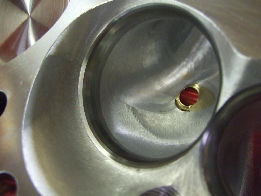
It doesnt mean every port design will benefit from it but I use it to manipulate the flow and put pressure on the ports in the area I want it.
OP....(great sig btw ), the winner is the higher flowing port that has the wing. Your hypothetical scenario with the wingless port flowing more would get my nod just based on the numbers.....the fact the other port has a wing and is flowing less doesn't make it more efficient....and if its flowing less that will effect the engine's ability to process air aka make power.
Also, its just the opposite on the valve events.....while an engine will naturally go thru the low and mid-lift numbers twice (on the way up the cam lobe and down the cam lobe), it spends much more time in crank degrees going across the broad nose of a modern hydraulic or solid roller design....while all the numbers really matter, the ones that matter most are probably .025 - .100 less than peak lift. For instance running a modern LSL lobe that lifts the valve to .625.....you would ideally want a head that's really good on the bench from .525 - .600 as the valve will spend alot of time there as it heads across the nose of the lobe (hitting peak lift once quickly in the process).
Whats the best scenario....a head that is explosive everywhere with a good balance of solid low numbers, a fat mid lift curve, and solid peak numbers thru a modest cross section so the velocity and charge inertia is high.....that's the killer combo that is responsive and extremely powerful. That's why most of the Mamofied stuff I do I pay more attention to increasing the overall efficiency than making the port flow more due to an increase in size. This approach gives the engine a completely different persona....its extremely explosive for lack of a better description at the moment.

Cheers guys
-Tony
I use them alot in my designs....check the newest Eliminator SBC designs I did for AFR (23' SBC").....the revamped "V2" version of our popular cathedral LS heads. The new not released to the public yet AFR BBF heads.....etc. etc.
Here is a (Mamofied) close up of a valvejob/bowl that clearly shows the wing

It doesnt mean every port design will benefit from it but I use it to manipulate the flow and put pressure on the ports in the area I want it.
OP....(great sig btw
), the winner is the higher flowing port that has the wing. Your hypothetical scenario with the wingless port flowing more would get my nod just based on the numbers.....the fact the other port has a wing and is flowing less doesn't make it more efficient....and if its flowing less that will effect the engine's ability to process air aka make power.Also, its just the opposite on the valve events.....while an engine will naturally go thru the low and mid-lift numbers twice (on the way up the cam lobe and down the cam lobe), it spends much more time in crank degrees going across the broad nose of a modern hydraulic or solid roller design....while all the numbers really matter, the ones that matter most are probably .025 - .100 less than peak lift. For instance running a modern LSL lobe that lifts the valve to .625.....you would ideally want a head that's really good on the bench from .525 - .600 as the valve will spend alot of time there as it heads across the nose of the lobe (hitting peak lift once quickly in the process).
Whats the best scenario....a head that is explosive everywhere with a good balance of solid low numbers, a fat mid lift curve, and solid peak numbers thru a modest cross section so the velocity and charge inertia is high.....that's the killer combo that is responsive and extremely powerful. That's why most of the Mamofied stuff I do I pay more attention to increasing the overall efficiency than making the port flow more due to an increase in size. This approach gives the engine a completely different persona....its extremely explosive for lack of a better description at the moment.
Cheers guys
-Tony
__________________

www.mamomotorsports.com
Tony@MamoMotorsports.com
Anything worth doing is worth doing well. Build it right the first time....its alot cheaper than building it twice!!
www.mamomotorsports.com
Tony@MamoMotorsports.com
Anything worth doing is worth doing well. Build it right the first time....its alot cheaper than building it twice!!
-Maybe GM eliminated it in preparation for direct injection? Maybe direct injection creates peak efficiency without need of the swirl ramp? IDK, but could be.
-How would the "wing" relate to a carb style intake where fuel enters @ the top center location of the intake which creates a denser charge due to its' cooling properties & more time/distance to atomize prior to reaching the CC. So, does the wing/swirl also create better efficiency in this scenario?
Aww, is the discussion over already ? Did that answer all your questions A.R. Shale Targa ?
So when Tony said, "I use it to manipulate the flow and put pressure on the ports" I think our answer might lie in that statement. It looks like in stock form, air would tumble off the edge of the swirl ramp and lead to stall. Maybe by forming a wing under the ramp, he avoids the stall by adding a little pressure.
A.R. Shale Targa, you've been researching this longer than me. What are your thoughts on swirl ramps ?
So when Tony said, "I use it to manipulate the flow and put pressure on the ports" I think our answer might lie in that statement. It looks like in stock form, air would tumble off the edge of the swirl ramp and lead to stall. Maybe by forming a wing under the ramp, he avoids the stall by adding a little pressure.
So I have my thoughts and beliefs about the ramp
Thread Starter
11 Second Club
iTrader: (2)
Joined: Feb 2011
Posts: 3,729
Likes: 15
From: Fredonia,WI
As many might remember, the first vortec 5.7s from the late 80s/early 90s had a swirl ramp bowl. Terrible for racing or anything over 4500 rpms, however they flowed a decent cfm per cc of volume ratio up to .400" lift. The flat tappets were 184/194 and like .384"/.396" ish lift and then the hydraulic rollers were 190/197 and .415"/.431" so low lift velocity was key to maintaining an efficiently atomized mixture (homogeneity) especially considering that a TBI was barely better than a q-jet carb.
It seems to me that whenever GM revisits flow ideas from old, they always have newer technology to help it work like they intended it to. Case in point the 95-99 vortex intake runner shape. Only a few years earlier the Imp SS iron LT1 heads revisited an entry shape originally released in 1973 version 882. Taller/ narrow at the top and a great low lift cfm to volume ratio.
So the symmetrical cathedral shape runner, tall and narrow with a race shaped floor that tilts as it approaches the short side combined with the ramp all contribute to help the air move in a way which prevents fuel molecular drop out. Again the fuel mixer (injecter) is better located yet not ideal as now with direct. Obviously now the runner only has to flow air and not a mix.
Spinning an airpump and max power come from bigger everything, as Grumpy Jenkins told us in the seventies. Today's street performers seem to focus on a broad, wide, efficient torque band. The most flow from the smallest runner. The most compression without detonation. The most rpms from the least duration camshaft. All working to maximize the engine's BSFC.
Long story, longer I feel the ramp helps yet some creative shaping can still help it flow well in the upper lift ranges and accomplish the tumble and turbulence GM meant for it to do.
Trending Topics
looking at a lot of different ports here, i dont have an answer. but check out that LS7 wingding compaired to the other ls, maybe the tested it south of the equator?  the rest of the port to bore, intake tract, valvetrain package and all that layout is the same so why the big change???? little valve angle change, and valve to bore,but still?
gm said, they had to endup useing a different head design (what the ls7 is) after the ls7 engine program got bigger (cubes). While using the other normal l92/ls3 castings at the time. And the LS stuff is not really race or performance, one thing ive been told to remeber about them. Not sure if this is just for a truck or all ls stuff in cars too (I bet its true) Is the engine will spend something like 95 (might even have been like 99%) of its entire life under 2,200 rpms. And remember that when you using your performance thinking, WOT is no high up in the big picture. just something to think about
the rest of the port to bore, intake tract, valvetrain package and all that layout is the same so why the big change???? little valve angle change, and valve to bore,but still?gm said, they had to endup useing a different head design (what the ls7 is) after the ls7 engine program got bigger (cubes). While using the other normal l92/ls3 castings at the time. And the LS stuff is not really race or performance, one thing ive been told to remeber about them. Not sure if this is just for a truck or all ls stuff in cars too (I bet its true) Is the engine will spend something like 95 (might even have been like 99%) of its entire life under 2,200 rpms. And remember that when you using your performance thinking, WOT is no high up in the big picture. just something to think about
LS1 Tech Stories
The Best V8 Stories One Small Block at Time

6 Common C5 Corvette Failures and What's Involved In Repairing Them
Pouria Savadkouei
Retro Modern Bandit Pontiac Trans AM Comes With Burt Reynolds' Autograph
Verdad Gallardo
Top 10 Greatest Cadillac V Series Performance Models Ever, Ranked
Pouria Savadkouei
Top 10 Most Powerful Chevy Trucks Ever Made!

Hennessey's New Supercharged Silverado ZR2 Has 700 HP
Verdad Gallardo
Coachbuilt N2A Anteros Is an LS2-Powered C6 Corvette In Italian Clothes
Verdad Gallardo
Awesome K5 Blazer Restomod Comes With C7 Corvette Power
Verdad Gallardo
10 Camaros You Should Never Buy

10 LS Engine Myths That Refuse to Die
Verdad Gallardo Thread Starter
11 Second Club
iTrader: (2)
Joined: Feb 2011
Posts: 3,729
Likes: 15
From: Fredonia,WI
looking at a lot of different ports here, i dont have an answer. but check out that LS7 wingding compaired to the other ls, maybe the tested it south of the equator? the rest of the port to bore, intake tract, valvetrain package and all that layout is the same so why the big change???? little valve angle change, and valve to bore,but still?
gm said, they had to endup useing a different head design (what the ls7 is) after the ls7 engine program got bigger (cubes). While using the other normal l92/ls3 castings at the time. And the LS stuff is not really race or performance, one thing ive been told to remeber about them. Not sure if this is just for a truck or all ls stuff in cars too (I bet its true) Is the engine will spend something like 95 (might even have been like 99%) of its entire life under 2,200 rpms. And remember that when you using your performance thinking, WOT is no high up in the big picture. just something to think about
the rest of the port to bore, intake tract, valvetrain package and all that layout is the same so why the big change???? little valve angle change, and valve to bore,but still?gm said, they had to endup useing a different head design (what the ls7 is) after the ls7 engine program got bigger (cubes). While using the other normal l92/ls3 castings at the time. And the LS stuff is not really race or performance, one thing ive been told to remeber about them. Not sure if this is just for a truck or all ls stuff in cars too (I bet its true) Is the engine will spend something like 95 (might even have been like 99%) of its entire life under 2,200 rpms. And remember that when you using your performance thinking, WOT is no high up in the big picture. just something to think about
Ford's Triton family was 85% by 1500 rpms. Crazy
I partially believe that GM knew DI was on it's way back in 05,06,07 era, but more less went rectangle port because they kept raising the floor off the deck. Ala C5R type stuff. The dramatic difference being that the air now moves over and drops down on the valve as opposed to starting low and having to raise before turning the short side.
Lastly the ultimate job of the runner/valve/chamber is to fill the coffee can (cylinder) below. It's interesting to wonder if clock or counter clockwise rotation does this better as the runner angles at the chamber's center.
AFAIK, Landspeed is not a sponsor here and does not have a website. I got the picture from their facebook page. Since the exhaust valve is on the wrong side I'm guessin they inverted the picture for some reason .... or it really is from down under where water drains the wrong way in the tub. I used a program and attached a inverted version of that pic.
LS1-450 removed his comment but it said something to the effect of "I would end up with scrap aluminum if I tried to pull that off". I think I would fare no better. It looks like they added metal to get that shape where as Mamo's wing looks like he worked with what was there. To have all 8 ports measure the same, I'm sure is beyond my skill.
studderin, I've seen pics of your work and admire your skill.
Yah, was in the process of re-writing it & got interrupted here. So, just deleted it. Why not just cast the wing into the bowl? Would also like to know which of the fuel delivery methods benefits most from the wing; carb style intake w/ fuel entering top center, stock FI location, direct injection, if any?