When you click on links to various merchants on this site and make a purchase, this can result in this site earning a commission. Affiliate programs and affiliations include, but are not limited to, the eBay Partner Network.
How To: Wipe Pattern for Roller Rocker and Pushrod Length
Just based on the number of times these questions come up, I've asked permission from some users to use their pictures and experiences to write this. Understand that most of the credit for this goes to half of LS1Tech, and the really good photos are from 5_Liter_Eater. The really crappy photos are off my phone.
So, here we go. How to check the wipe pattern on roller rockers:
For checking the wipe pattern, the below method uses yella terra�s. You can use this method I�m sure for any roller rockers, but YT�s are what are handy, so they get the photographs. Go slowly and methodically. No need to rush. Accuracy and precision are more important than speed.
I cannot stress this enough. Work with a good vendor. You are making an investment in your vehicle�s performance and longevity if done right. You might or might not want some support later on, or you may find you can�t get a hold of certain shims, etc. Pick a vendor you can trust and work with that vendor. You can read threads on here for a short list of extremely trustworthy vendors. I don�t want to post my shortlist for fear of leaving out other very good vendors. There�s a convenient list of links down the right hand side of your screen. Did I mention you want to find a good vendor to work with?
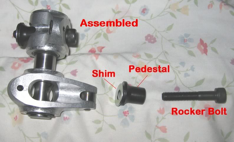
Step 1 -- Here is a picture of the Yella Terra rockers. This process should work with any roller tip rockers, but since we have YT�s available due to the builds, these are what we will use for illustration. Note the pedestals, shims, and rockers on the left, and on the right, how they get stacked properly.
They are built into pairs, so you have to do everything two at a time when working with them.
Bottom View:
Top View. Note the 1.7 stamp that is offset and not centered? This indicates the most recent revision of the YT's. These are the good ones:
Step 2 -- You only need to do this for one cylinder. Cylinder 1 or 2 are the easiest to work with. Most use 1, since the timing marks are also helpful. Makes sure you are on the base circle, and neither valve is being lifted. The best place is near TDC of the compression stroke. Install an adjustable pushrod (or two if you want) and two of the rockers onto the head. Don�t use any shims, just use the pedestals. Adjust your adjustable pushrod length until you just barely have lash. Even zero lash is fine for this step. You may have to remove and install your rockers several times if you can�t get to the adjustment with the rockers in the way. Measure the pushrod if you have 12� calipers. Make a mental note of this length for later. I rounded mine off to 7.5�. Not super critical for this early step.
Step 3 -- Once you have the pushrod length basically right from step 2, tighten the nuts to try to keep the length from drifting too much. It is helpful to put some Teflon tape on the adjustable pushrod threads to reduce potential thread slippage. Mark the valve tips with something. I have used black moly grease. Others have used sharpie, dry erase, indicating die, etc. Something to leave a mark but then get removed by the roller tip on the rocker.
Dry Erase:
Grease. If you don't dab it to be almost invisible, it will look like this and give you crappy results later on. Just showing an example of what not to do:
Step 4 -- Now, install a pair of rockers, but put the shims under the pedestals. You have to shim both equally. The factory shims from YT are 0.062�. This should give you enough lash to prevent to roller from touching the valve tip with the bolt fully tightened. Once you have the rocker bolt fully tightened, allow the tip to rest gently on the valve tip.
Step 5 -- Rotate the engine 2x until you are back on the base circle. You can tell by watching the rockers. When they both look closed, rotate another thirty degrees or so for good measure. If you are going clockwise, you�ll see the exhaust lobe open, then the intake lobe start to open as the exhaust valve is closing, then the intake valve will close. The reason for going the extra 30 degrees is to not let the extra lash fool you.
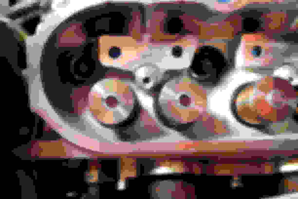
Step 6 -- Remove the rockers without allowing the rollers to touch the valve tips. You should now be able to see your wipe pattern:
Here is an example of an accurate wipe pattern using the dry erase marker method for coloring the valve tips. Note the nice clean, sharp lines separating where the roller touched and didn't touch:
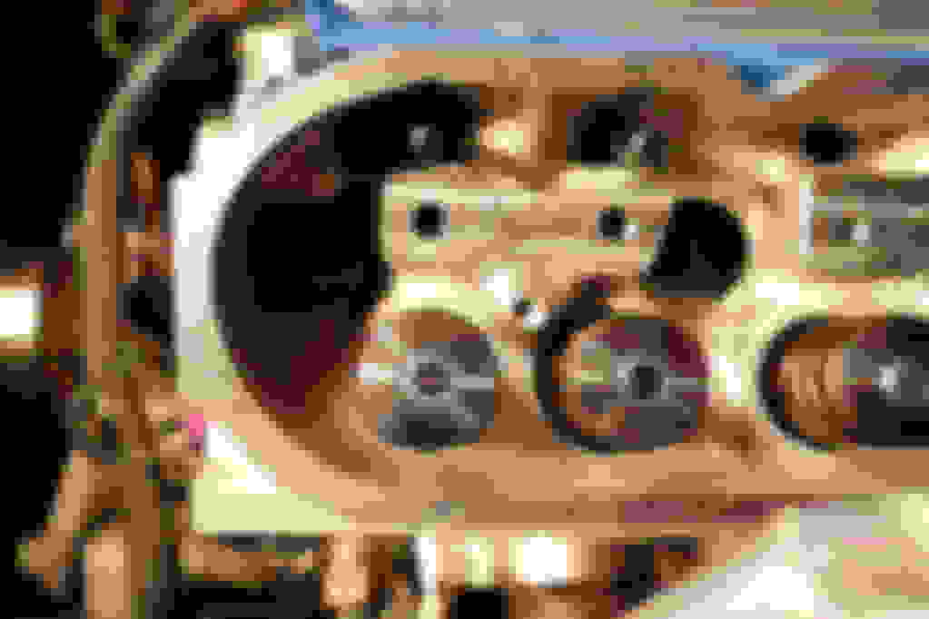
Here is an example of an accurate wipe pattern using the grease as the indicator:
Here is a crappy picture of a crappy wipe pattern from using too much grease. You can sort of see the pattern, but it isn't clear or sharp at all. Hopefully shoing the bad examples is as helpful as the good examples:
Step 8 -- If your wipe pattern is toward the intake side of center and wide, you probably need a little bit more shim. Shim thicknesses on the order of 0.100 to 0.130 are common, so don�t be surprised if two YT shims under the pedestal is perfect. You might find yourself sitting on a bucket at home depot measuring washers for three hours to get a variety of shim thicknesses with which to work (screw you, grammar police!).
Step 9 -- As you increase shim thickness, you should see the wipe pattern move further toward the headers and the line get thinner. In my case, 0.150 shims made the thinnest line, but 0.125 shims were the best centered. If you have to compromise (likely), go with your best centered wipe, not necessarily the thinnest line. Once you have established your wipe pattern, you need to find 16 of these. So, another three hours at Home Depot sitting on an upside down bucket with your calipers, and you have your shims. Great! Now you can move onto pushrod measurements.
Here is a great example of what you want your wipe pattern to look like. Centered, tight, and even:
These two wipes were not enough shim. See how it is on the intake side of centered and rather wide:
This wipe was too much shim. See how it is to the exhaust side of centered, but very tight. Yes, it's the same picture with too much grease, but it shows what happens when you go too far on the shim height:
Here is another shot of a wipe pattern that indicates you have it about right:
You want .060" or less of sweep pattern. THIS MORE IMPORTANT THAN CENTERED. If it is centered but wide you are loosing lift..1 and working the valve back forth wearing out the valve.
The method using Half lift and math will get you proper rocker geometry. Once you have established proper geometry then the pushrod length is a result.
To have minimum sweep and perfectly centered is a perfect world idea...we don't live in a perfect world so it would take an intake rocker and exhaust rocker for every head with every length valve to achieve this and I don't know any rocker mfg that does that.
Each case is a compromise and you want the narrowest sweep pattern on the tip. Perfect is .060" or less. Anymore and you have wasted motion and will wear out valve guides.
When I set mine up I was thinking that you're better to be centered rather than always pushing one way or the other. I can edit that last step if it's better the other way. But I would have thought if you're way to the exhaust side all the time you would scrub the intake side of the guide.
I have also read that with heavier springs having peak lift near center ensure maximum spring force has minimum side force on the guide. Of course this is under pure statics, dynamics will change things a bit.
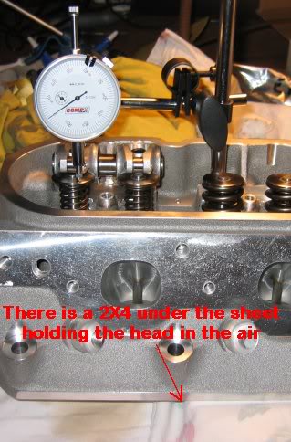
Here is a thread I put on Corvetteforum some years ago when I did mine. I did mine with the heads off the car and used a dial indicator to measure lift. This approach removes any lifter plunger movement error from the valve lift. If memory serves me correctly, my final width was 0.045" after shimming.
I have had several people e-mail and ask how to do this so I thought I would post this for discussion and information. I just finished setting up the wipe pattern of my Yella Terra roller rockers on my new AFR heads. The Yella Terra rockers are fixed fulcrum rockers (as opposed to a fully adjustable rocker like the Crane I set up on my current configuration) and are furnished with a rocker pedestal and a single shim that is 0.048” thick, which when placed under the pedestal, will raise the fulcrum of the rocker and move the roller location towards the exhaust side of the valve stem. The goal is to center the wipe pattern on the valve stem and minimize the width of the pattern. When the width is reduced over the course of rocker motion, then the side loading into the valve guides is also reduced. This not only provides faster valve motions but also minimizes valve guide wear. Below is a photo of how the Yella Terra setup is installed with the pedestal and shim (if used) under the rocker shaft and the bolt passing through the assembly and into the threaded hole in the head.
I am doing this on the workbench but this can also be done on the car. The workbench has the advantage that there is more time to set things up and if parts are needed the car won’t be down as it would if you were in the middle of the head installation. Plus, it’s easier on the back.
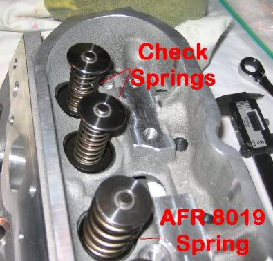
The first step is to remove two valve springs and replace them with checking springs. I have two sets of checking springs and I used the stiffer set since they provide more force against the rocker to help in wiping off the ink that is applied to obtain the final wipe pattern.
Once the check springs are installed, set the cylinder head in the air such that the valves can be manually operated without contacting the workbench surface. Using a dial indicator allows you to manually operate the rocker arm to the required valve lift. Since the final wipe pattern is lift sensitive, you have to ensure that the motion you are moving the rocker through imitates that which will be driven by the cam.
The next step in the operation is to setup your rockers and snug the bolts. There is no need to fully torque the bolts and load the threads in the aluminum head. Hand snug is fine and will eliminate thread wear as the bolts are taken in and out several times during the process. Once the rockers are in place with the shims that are being checked, and your measurement method is setup to determine how much the valve is being moved, use a Sharpie to spread black ink on the upper surface of the valve stem. I have found it best to not allow the ink to dry too long as with checking springs it doesn’t wipe off as well. Instead, I use a cotton swap and pull off most of the cotton then soak it with ink from the Sharpie. Then I simply rotate the rocker back off of the valve stem and apply the ink. After it is just dry, then the wipe test is conducted by rotating the rocker arm by hand in the same manner as the pushrod and cam would if the head were on the motor. This process is repeated until a satisfactory wipe pattern is found by adjusting the height of the shim. A thicker shim should push the wipe pattern towards the exhaust side of the valve stem. This will be critical later as the pushrod length changes approximately 0.016” in length for every 0.010” of shim you add to the rocker pedestal so that the wipe pattern needs to be established first followed by the pushrod length.
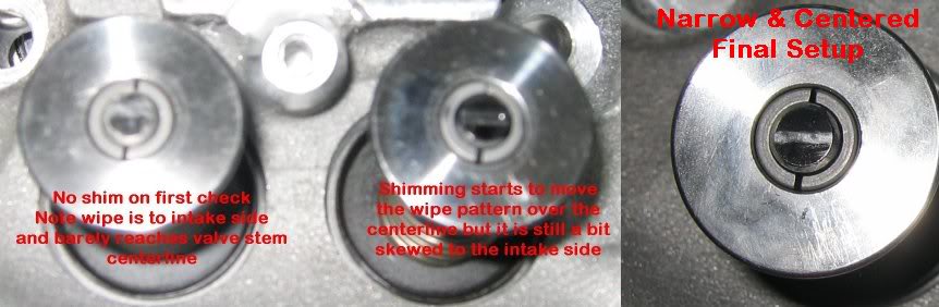
I started the process with no shim in place under the pedestal and then added shims until I got the desired wipe pattern. Washers can be used and stacked for this process but once a thickness is found you need to find a single piece shim of the correct thickness. In the photo below (sorry for the crappy photography), three of the patterns are shown. On the left is the wipe pattern without a shim. Notice that the wipe pattern is towards the intake side of the valve stem and barely gets to the valve stem center over the course of travel of the roller on the rocker. In the middle photo, shimming has now moved the wipe pattern towards the center of the valve stem. It is still biased to the intake side and a little wide. The final wipe pattern on the right is the shim setup I will use for final installation, as I am very pleased with the final wipe pattern obtained. Note that the shim value can be different for any given setup, the point being that simply bolting on the rockers from the box would have yielded the pattern on the left and likely resulted in not only disappointing results but higher than necessary valve guide wear for my installation. I bought my final shims (11/32" ID, 13/16" OD from McMaster-Carr, which are available in a lot of thicknesses. These were pretty much a perfect fit under the pedestal if you need a thickness that differs than the one provided by Yella Terra for any reason.
I wonder if the application should determine how you set it. If I'm racing professionally and I know I'm going to tear the heads off every so often, install fresh valve guides, seals, etc, I would not want to give up any performance and would definitely want the geometry for max lift.
For a high end street machine expected to go many, many miles, perhaps driven daily, I'd be willing to give up that last ounce of performance for durability.
Maybe the ideal for one scenario isn't ideal for the other, so you compromise - like when you pick a cam?
This should not be done until you have your rocker install shims determined.
From this point forward, keep the rockers with the same cylinders on the engine. Once you check the pushrod length for a cylinder, keep those rockers with that cylinder. I very highly recommend bolting them back on after you remove the adjustable pushrod for the last time. Of course you could mark them, but I prefer foolproof whenever I can get it. For my own sake. Also, it is very helpful to have two adjustable pushrods instead of 1. Cuts the time to do this in half. Do yourself a HUGE favor and get a 12� digital caliper. At the very least, get a 8� caliper. I've read posts on using the number of rotations to calculate pushrod length, which may be OK for stock lifters, but I found it to be easier and more certain to just measure with a caliper.
Step 1 --Your adjustable pushrods should be pretty close to a good starting point from doing your wipe pattern, unless you did something to them. Or perhaps you took note of the length measurement as recommended above. Add your half your total shim thickness to the pushrod length from your wipe check as a good starting point. For reference, I started mine at 7.6300�. I recommend doing this with cylinder 1 or 2 first to get the technique. Once you get it down, I would then start with the back cylinders and work forward. If you bolt your rockers to keep them with the correct cylinders, it would be more difficult to get the back rockers and shims in and out with the other ones in the way (especially in a F-body under that cowl), but the fronts have easy access.
Step 2 -- Insert your adjustable pushrods, then install the rockers with the correct shims under the pedestals and put *some* torque on the bolt, but not much. More than hand tight is fine, unless you have vice-grip hands. If you do, then hand tight is fine. If there is any lash, remove the rockers, remove the pushrods, and use the calipers to guide your adjustment up 0.010�. Make sure as you do this, you don�t lose track of which PR is intake and which is exhaust. I only removed the one I was working on and reinserted it after adjusting before removing the other so I wouldn�t get them mixed up in my hands.
Step 3 -- Repeat step two until you lose lash. Make your adjustments in 0.010” increments. When you lose lash, make the adjustable .005” shorter and try again. For argument’s sake, assume you lost lash at 7.670, and then got it back at 7.665. You can then split the difference and do one at 7.668. If you have lash, then at 7.668, then 7.669 is your number. If not, then try 7.667, then 7.666 if necessary, until you find the point where you JUST start to get lash. Measure the PR as you remove it this last time and write that number down. Make a table as you go so you know which length rods go where. This is NOT the number you call the vendor with just yet.
Step 4 -- Now, the disaster check. How much preload do you want? Well, if you installed Johnson 2126ST’s, you want about 0.038” preload. Sorry, that’s the only one I know. On stock lifters, you tend to see 0.070” up to 0.100” recommended, but I'm just parroting what I've read on that one. This is when it is good to be working with a trusted vendor. Sometimes you just need to ask these questions, and you feel dumb, and the good vendors will wait until after you hang up to call you a moron, so you won’t have to feel bad about it. Anyway, make sure you know what preload you are looking for.
Step 5 -- Add the preload to your measurement from step 4, make your adjustable PR this exact length, install it, and the rockers. OK, at this point, just double check you are definitely on the base circle. It’s easy to get ahead of yourself. Now, as you tighten it, your manly vice-grip hands are going to be able to partially preload the lifters. Don’t do that. You need to find exactly zero lash on that bolt. What I found works great is to use a 3” extension and the socket as a screwdriver. Gently and slowly turn it until it requires effort to keep turning. Slightly loosen and then come back to just touching. And one more time, very slightly loose and just barely touching.
Step 6 -- Put the ratchet on or (allen wrench) very carefully so as not to rotate the bolt until you are ready. Make sure you have plenty of freedom of movement. Tighten the bolt, keeping very close track of how much the wrench rotates. It will spin relatively easily and then start requiring some real torque to go any further. Right when you hit this point, you are no longer preloading the lifter, but are actually torqueing the bolt. How much did the wrench rotate? Figure on 0.075” per rotation. Did you get 180 degrees? You just got 0.038” of preload. Did you get 360 degrees? You just got 0.075” of preload. Did you get a full turn and a half (540 degrees)? You got 0.113” of preload.
For the build being photographed, the desired preload was 0.038", which means 180 degrees or a half turn on the wrench
Last edited by Darth_V8r; Dec 23, 2015 at 03:12 PM.
Reason: Comment about the specific build just above the pictures
Step 7 -- If you got within 30 degrees of your target, you can run with it. If not, you�ll need to modify your pushrod length to get in range of the right number. With higher preloads, your margin for error might be greater as well. Again, verify with your very polite vendor who is very patient with you on the phone at 3am how much of a range on preload is acceptable if you get something you�re not sure about. And look, if you�re not sure and feel stupid calling, err on the side of caution and get it closer. After all, it isn�t rocket surgery. (that comes later)
Step 8 -- So, following steps 2-7, you feel like you got the technique down? Awesome, now start with cylinder 7 and work forward. Then go to 8 and work forward. Remember to keep the rockers with the correct cylinder � either by bolting them on or marking them. Also, since shims can vary slightly, Keep the same shims with the same rockers at all times. Another good reason to bolt them in place while you wait for your pushrods.
Step 9 -- Now, check out these two tables below. Notice there is a slight variation for almost every position? That�s cause the guy who got the chart on top used a cam motion cam and the other guy used a comp cam. Kidding, that has nothing to do with it at all. Sometimes, you will get a rogue length or two. This is why you were super diligent and checked all 16 instead of checking cylinder 1 only and calling for a full custom set at 7.705�.
Step 10 -- Now, if you�re installing stock lifters, you can pick an average number and order them all to that length. There will be some natural variability in your pushrod lengths. I found the range to be +/- 0.004�. No big deal, this will work to your advantage, anyway. If you�re working with short travel lifters, you�re likely going to order a few different lengths. Remember that super awesome and patient vendor you chose to work with? Yeah, here is another good reason. Call him up, go over the measurements, and both of you agree on what length pushrods you are going to order. You�ll end up getting something like 7 of one length, 4 of another, 2 of another, and 3 individually chosen.
Step 11 -- Having called up your vendor and got the pushrods all ordered up, you�re going to hit the fast-forward button for three days or so while you wait for them to show up on your doorstep. Don�t cue up the Jeopardy theme song while you wait. It gets old way before the stuff arrives. Just try to focus on other parts of the build. Now is an excellent time to work on your headers, water pump, front cover, clutch, or get your back waxed for all I care.
Step 12 -- So, the UPS guy just dropped off your rods. Awesome. Unpack the box, and measure your pushrods. Remember that chart that showed all these slightly varying lengths between 7.665 and 7.669 as a zero lash number? You probably just ordered seven of them at 7.705�. As you measure all your 7.705� pushrods individually, you find that you magically have seven ranging in length from 7.702� to 7.709�. Brace yourselves, but remember that �rocket surgery� thing we mentioned in step 7 that was coming later? Here it is. Use the shorter rods for the shorter lengths and the longer rods for the longer lengths. :mindblown:. Everybody OK out there? Good! Whew!
Step 13 -- If you did what I did and bolted the rockers to their respective cylinders to avoid confusion, then only remove the rockers when you are ready to put the pushrods in. Work one cylinder at a time � unbolt, insert rod (giggedy), install rockers, move on to the next cylinder.
Step 14 -- Remember that double check we did before in steps 5-7? You mean we have to do that again? No, you don�t HAVE to, but you should - especially if you installed short travels. Better to find out now that either you goofed a measurement, or swapped two rods by mistake between measuring and installing, or got an out of spec pushrod now than to find out later in the form of a low-power cylinder or worse. Plus you�re installing them anyway, you might as well keep track of the wrench rotations during installation. If you find that you have some that are coming up with less preload or more, but they were in the same measurement group, try swapping rods before panicking. If you can�t resolve it and you just have that one rod that is coming out not quite right, call your trusty vendor up. It might actually still be OK if you got, say, 220 degrees of rotation instead of 180 on the wrench. Just stay in touch with your vendor.
Are there other ways to get it done? I'm sure there are. but this method, while tedious should get you very good results, and if for some reason you decided to completely scrap your measurements and start over, you should get the same numbers within .002" either way. Good luck on your builds!
6 Common C5 Corvette Failures and What's Involved In Repairing Them
Slideshow: From wobbling harmonic balancers to failed EBCMs, these are the issues that define long-term C5 ownership and what repairs typically involve.
Retro Modern Bandit Pontiac Trans AM Comes With Burt Reynolds' Autograph
Slideshow: A modern Camaro transformed into a retro icon, this limited-run "Bandit" build blends nostalgia with brute force in a way few revivals manage.
Top 10 Greatest Cadillac V Series Performance Models Ever, Ranked
Slideshow: Cadillac didn't just crash the high-performance luxury vehicle party, it showed up loud, supercharged, and occasionally a little unhinged...
Coachbuilt N2A Anteros Is an LS2-Powered C6 Corvette In Italian Clothes
Slideshow: A one-off sports car that looks like a vintage Italian exotic-but hides a C6 Corvette underneath-just sold for the price of a new mid-engine Corvette.