
Follow along with an engine build @ Weber Racing Engines!!


 04-15-2008, 09:08 AM
#42
Banned
Thread Starter
iTrader: (4)
Join Date: Jan 2007
Location: North Ridgeville, Ohio
Posts: 539
Likes: 0
Received 0 Likes
on
0 Posts
Ok everybody we are back to working on this engine. There was a good break in there due to some changes in the build. The day we started this thread we decided to go solid roller and the guys at TEA had to put together a custom solid roller setup set of 235cc Trickflow cylinder heads. Since we knew the heads would be a little bit and we were also waiting on the custom Wiseco pistons we took a break to get some other projects completed and out the door.
Now that the block is complete it went into the jet washer and was cleaned and bagged to wait in line for the assembly room. Unfortunatly I missed this part, but really there is nothing to see there. The block is in the jet washer and blown out with an air gun so it does not rust.
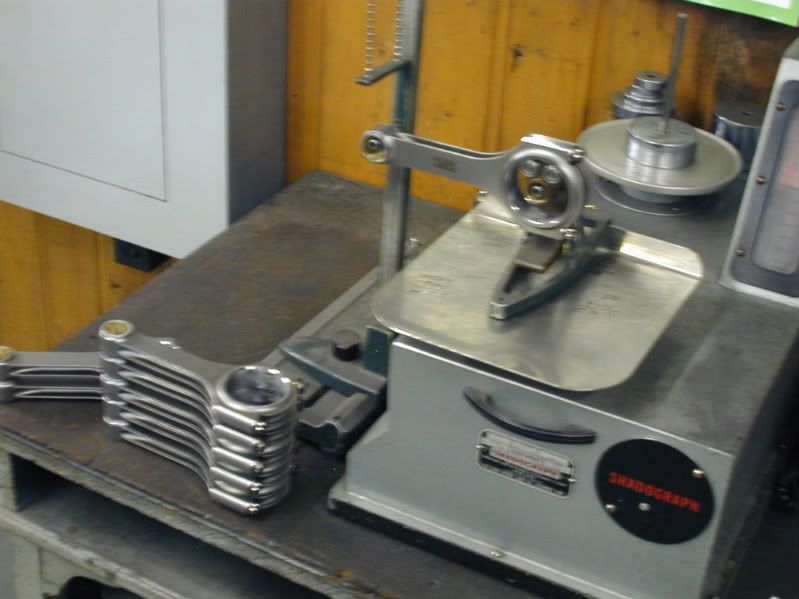
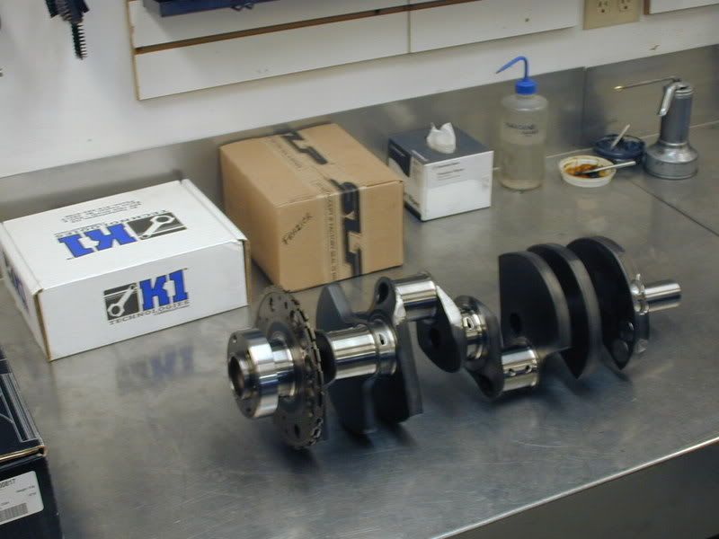
We have everything here for the rotating assembly to be balanced.
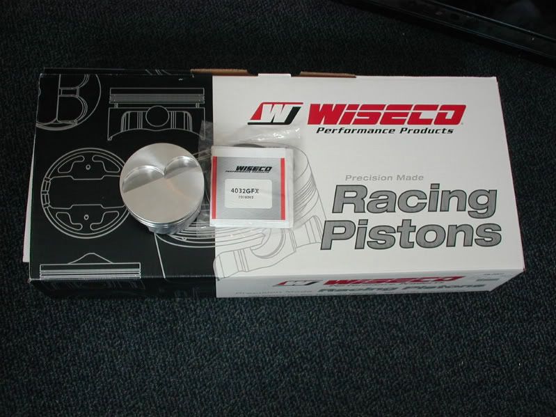
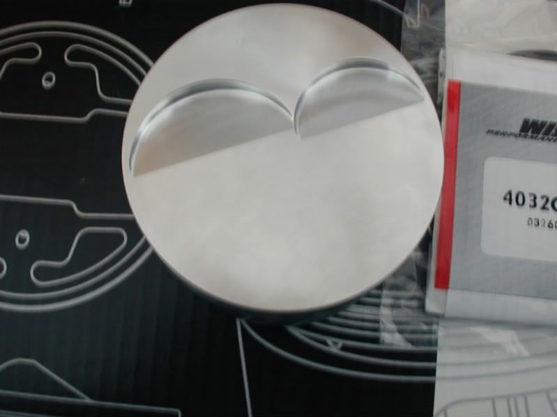
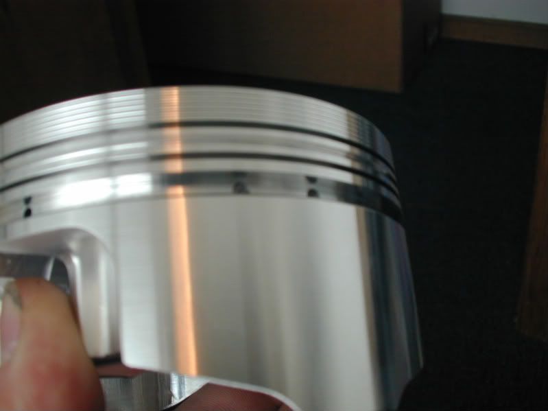
Here are the custom pistons from Wiseco:
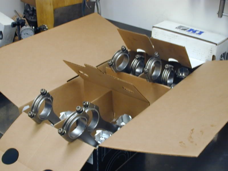
The K1 Tech Connecting Rods (Which you will see pictures of later.)
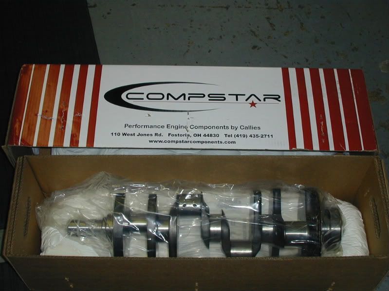
Callies Compstar 4.000 Stroke Crankshaft
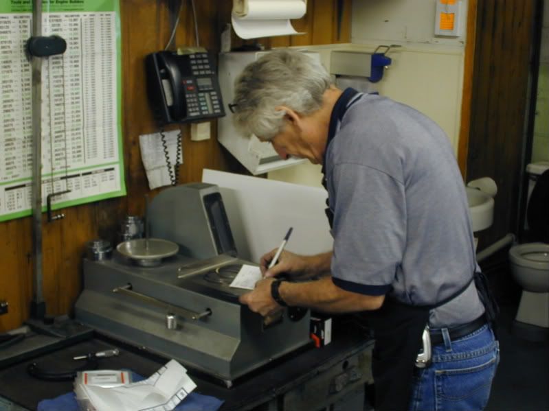
Everything is taken over the weigh station where Dave Weber will get rod, piston, ring and connecting rod weights to establish a bobweight so he can balance the crankshaft.
This is how the big end of the crank is weighed:
The pistons:
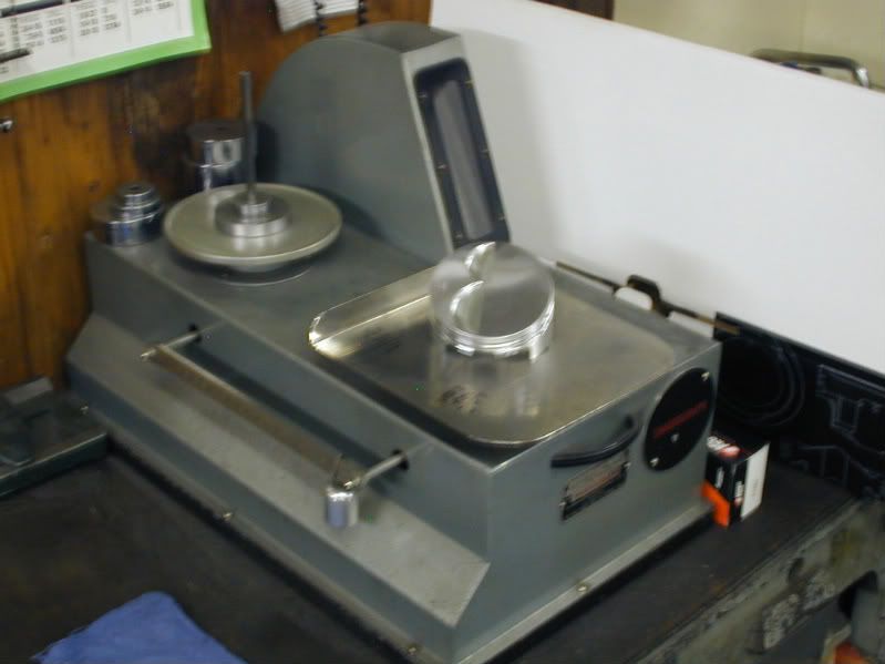
Piston Rings:
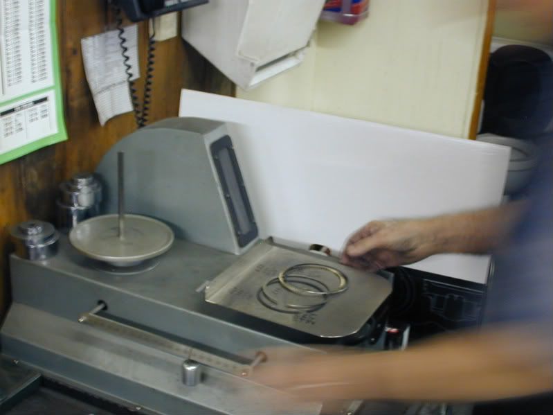
The rod bearings are also weighed and weights are recorded on a balance card that is kept on file:
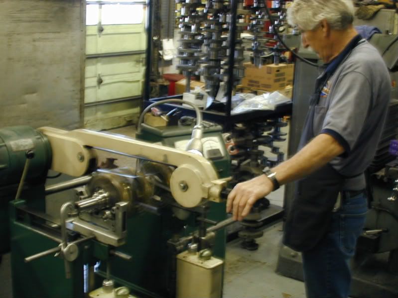
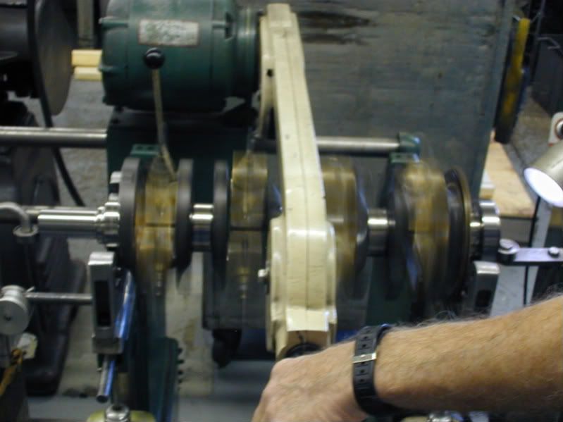
Next Dave sets up the crankshaft in the balancer with bobweights attached. When a crank is balanced it should sit in the balancer and not want to spin on its own at any point. There is alot more to balancing that I am not going to get into here. The bottom line is the crankshaft needs to be balanced so the engine will not vibrate and create harmonics and the engine to vibrate. This ensures a smooth running engine.
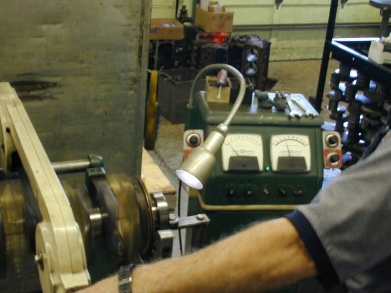
Here is a picture of Dave spinning the crankshaft on the balancer. While the crankshaft is spinning Dave is looking at the gauges to detect any loads that would detect the crank being out of balance.
Even though these cranks are rough balanced, they still are not perfect. This one was off quite a bit. Dave than adds clay to the counter weights on the crankshaft. This clay is added and removed until a perfect balance is found.The clay is than weighed so we can see how much weight may need to be added or subtracted from the throws of the crank. This one needed some weight taken out.
When the weight is taken out of the crank by drilling into the counterweights of the crankshaft. Sorry I missed this part so do no have any pics of it. I will try to catch Dave working on another crank and get a pic for everyone to see.
Now that the block is complete it went into the jet washer and was cleaned and bagged to wait in line for the assembly room. Unfortunatly I missed this part, but really there is nothing to see there. The block is in the jet washer and blown out with an air gun so it does not rust.
We have everything here for the rotating assembly to be balanced.
Here are the custom pistons from Wiseco:
The K1 Tech Connecting Rods (Which you will see pictures of later.)
Callies Compstar 4.000 Stroke Crankshaft
Everything is taken over the weigh station where Dave Weber will get rod, piston, ring and connecting rod weights to establish a bobweight so he can balance the crankshaft.
This is how the big end of the crank is weighed:
The pistons:
Piston Rings:
The rod bearings are also weighed and weights are recorded on a balance card that is kept on file:
Next Dave sets up the crankshaft in the balancer with bobweights attached. When a crank is balanced it should sit in the balancer and not want to spin on its own at any point. There is alot more to balancing that I am not going to get into here. The bottom line is the crankshaft needs to be balanced so the engine will not vibrate and create harmonics and the engine to vibrate. This ensures a smooth running engine.
Here is a picture of Dave spinning the crankshaft on the balancer. While the crankshaft is spinning Dave is looking at the gauges to detect any loads that would detect the crank being out of balance.
Even though these cranks are rough balanced, they still are not perfect. This one was off quite a bit. Dave than adds clay to the counter weights on the crankshaft. This clay is added and removed until a perfect balance is found.The clay is than weighed so we can see how much weight may need to be added or subtracted from the throws of the crank. This one needed some weight taken out.
When the weight is taken out of the crank by drilling into the counterweights of the crankshaft. Sorry I missed this part so do no have any pics of it. I will try to catch Dave working on another crank and get a pic for everyone to see.
 05-14-2008, 07:41 AM
#44
Banned
Thread Starter
iTrader: (4)
Join Date: Jan 2007
Location: North Ridgeville, Ohio
Posts: 539
Likes: 0
Received 0 Likes
on
0 Posts
The short block is complete. The heads are here and the intake came in from Nitro Daves. The intake was disassembled and is being ported. I will up date this soon. We have been absolutely slammed here lately, which is normal for this part of the year. We are still waiting on rocker arms from Crane that the customer requested.
 05-15-2008, 09:17 AM
#47
Exactly there is so much more to it than just getting a block and buying a rotating assembly and slapping it together in your garage. Can you slap one together, yes but how long will it last and how much power will you be down for not line honing and following procedures.
Great thread by Leo and Weber.
06-19-2008, 04:02 PM
#48
Banned
Thread Starter
iTrader: (4)
Join Date: Jan 2007
Location: North Ridgeville, Ohio
Posts: 539
Likes: 0
Received 0 Likes
on
0 Posts
Well we have been SWAMPED. We were waiting on the new Crane Roller Rockers to arrive, which they finally have. The cam, heads and intake have all arrive. The intake which was plumbed by Nitrous Outlet has been disassembled to be ported. Sorry I did not get any pics before it was taken apart, but will be put back together as soon as the porting is completed.
So to continue.........................
After balancing all of the parts are brought into the engine assembly room and setup for short block assembly.
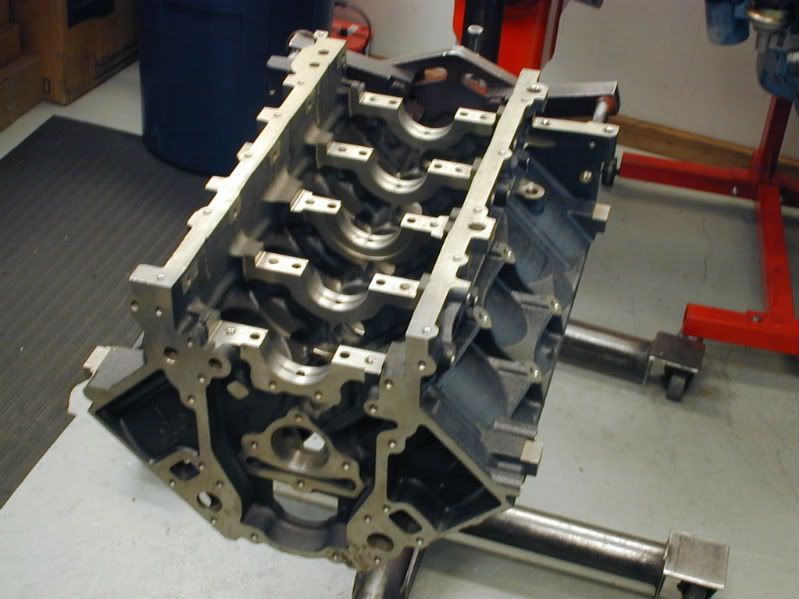

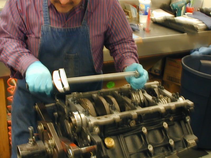
Once everything is organized Jim proceeds to install the cam bearings.
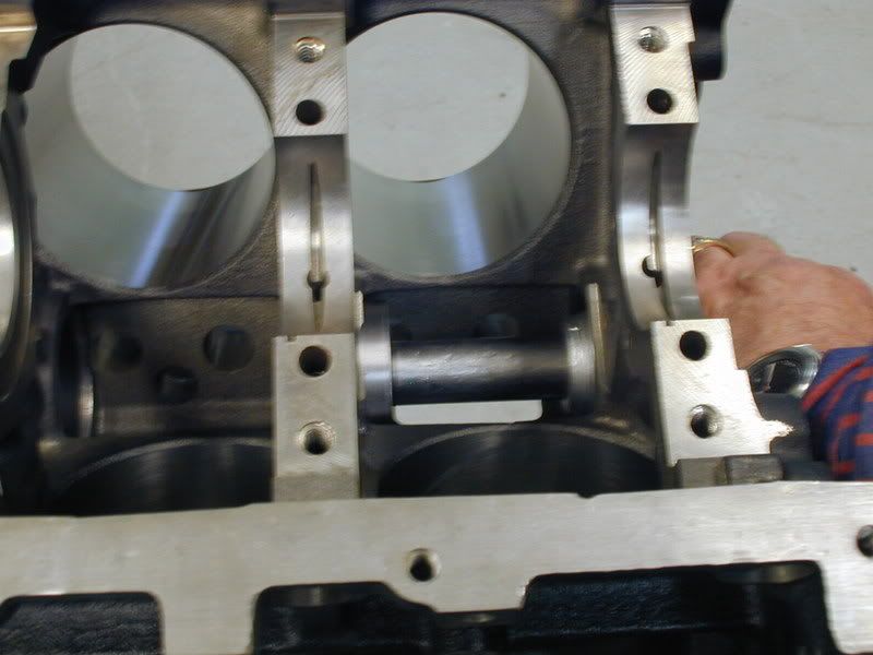
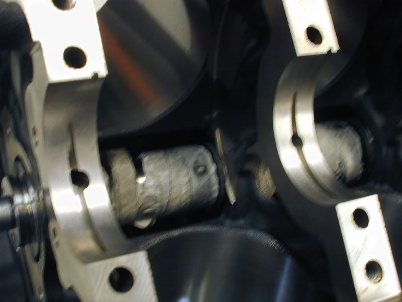
After the cam bearings are installed our "test: cam is installed to make sure there is no binding in the cam tunnel:
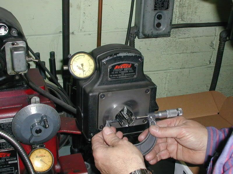
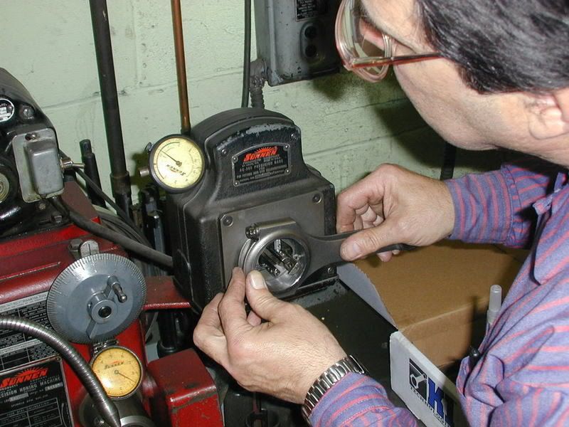
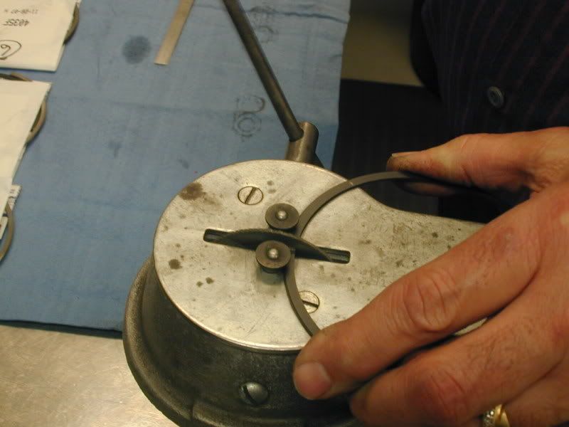
Next Jim is going to check the big end of the connecting rods for proper bore size. Even though these are new rods, we always double check the manufacturers work to make sure it meets our requirements. The rods are torqued as they would be installed and than are taken over to the Sunnen Rod Hone Machine to check size.
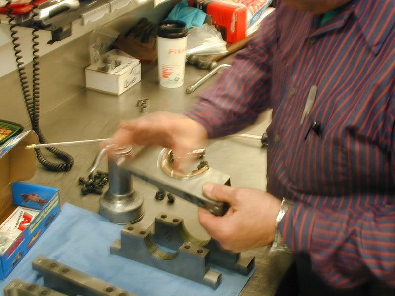
Here is a picture of Jim setting the micrometer for the big end diameter, than checking the rod on the Sunnen Rod Hone machine.
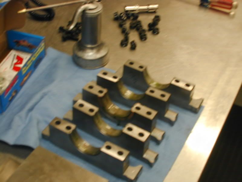
Next Jim goes back to the assembly room to check the main bearing ID. The main bearings are installed, the main cap is torqued and measured with a dial bore gauge.
The size of the mains are recorded and than Jim moves on to crankshaft to measure the O.D. on the main journals.
Between the 2 measurements we subtract the size of the crankshaft from the ID of the Main Cap and that give us our bearing clearance. Since we machine the blocks in house our tolerances are right in spec 99.9% of the time. If there is an issue at this point, we can use an over or under size bearing to make up for any clearance issues.
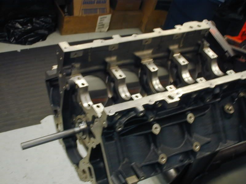
Next the main bearings are coated in a thin layer of oil and crankshaft thoroughly cleaned and is laid into the block:
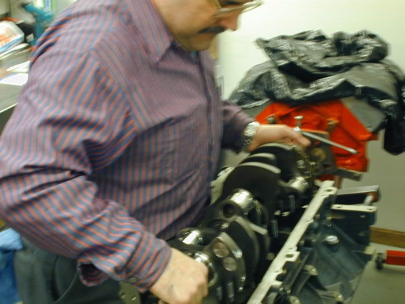
Next the main caps are oiled, installed and torqued to specification:
After that we test spin the crank to make sure there is no binding. We also check the end thrust to make sure it is within allowed tolerances. Once that is verified, its on to assembling the pistons and connecting rods.
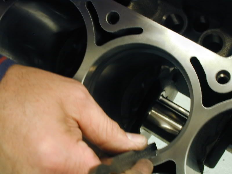
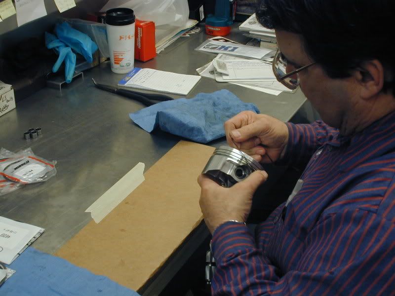
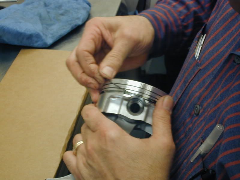
The first part of assembling the piston and rod assemblies the rings need to be gapped.
The rings are fit into the bore and measured with a taper gauge to check for proper ring gap. The ring has to be test fitted first to establish a starting point to see how much material needs to be removed to establish desired ring gap. This can vary from engine to engine depending on the use and power adders being used on the engine.
Jim checking the ring gap:
So to continue.........................
After balancing all of the parts are brought into the engine assembly room and setup for short block assembly.
Once everything is organized Jim proceeds to install the cam bearings.
After the cam bearings are installed our "test: cam is installed to make sure there is no binding in the cam tunnel:
Next Jim is going to check the big end of the connecting rods for proper bore size. Even though these are new rods, we always double check the manufacturers work to make sure it meets our requirements. The rods are torqued as they would be installed and than are taken over to the Sunnen Rod Hone Machine to check size.
Here is a picture of Jim setting the micrometer for the big end diameter, than checking the rod on the Sunnen Rod Hone machine.
Next Jim goes back to the assembly room to check the main bearing ID. The main bearings are installed, the main cap is torqued and measured with a dial bore gauge.
The size of the mains are recorded and than Jim moves on to crankshaft to measure the O.D. on the main journals.
Between the 2 measurements we subtract the size of the crankshaft from the ID of the Main Cap and that give us our bearing clearance. Since we machine the blocks in house our tolerances are right in spec 99.9% of the time. If there is an issue at this point, we can use an over or under size bearing to make up for any clearance issues.
Next the main bearings are coated in a thin layer of oil and crankshaft thoroughly cleaned and is laid into the block:
Next the main caps are oiled, installed and torqued to specification:
After that we test spin the crank to make sure there is no binding. We also check the end thrust to make sure it is within allowed tolerances. Once that is verified, its on to assembling the pistons and connecting rods.
The first part of assembling the piston and rod assemblies the rings need to be gapped.
The rings are fit into the bore and measured with a taper gauge to check for proper ring gap. The ring has to be test fitted first to establish a starting point to see how much material needs to be removed to establish desired ring gap. This can vary from engine to engine depending on the use and power adders being used on the engine.
Jim checking the ring gap:
06-19-2008, 04:04 PM
#49
Banned
Thread Starter
iTrader: (4)
Join Date: Jan 2007
Location: North Ridgeville, Ohio
Posts: 539
Likes: 0
Received 0 Likes
on
0 Posts
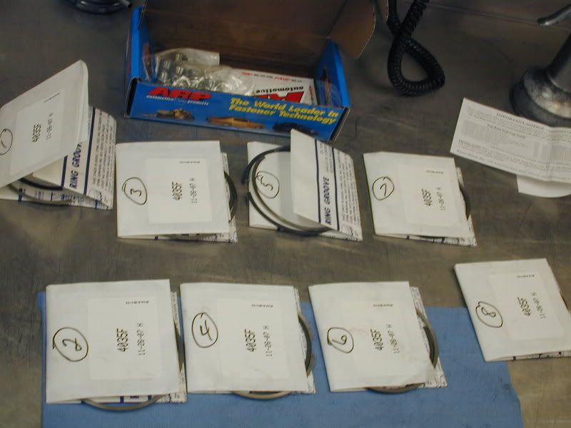
Next the rings are filed to size on the piston ring filer:
This process is repeated until the desired ring gap is achieved.
As the rings are completed they are laid out and numbered based on the cylinder they will be installed on.
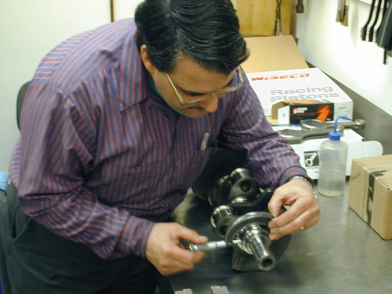
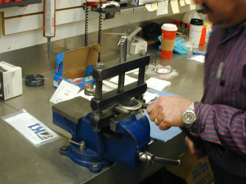
After the rings are filed the connecting rods and the pistons are put together:
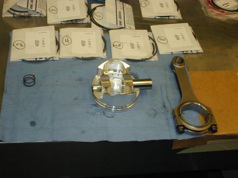
First the rods are setup in the connecting rod vise and the bolts are loosened:
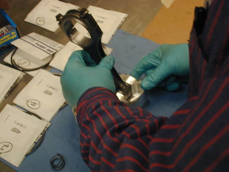
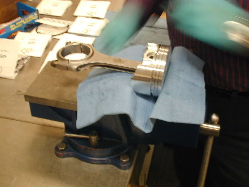
Next the rod is positioned in the piston and the wrist pin is lubricated and slid in to hold them together:
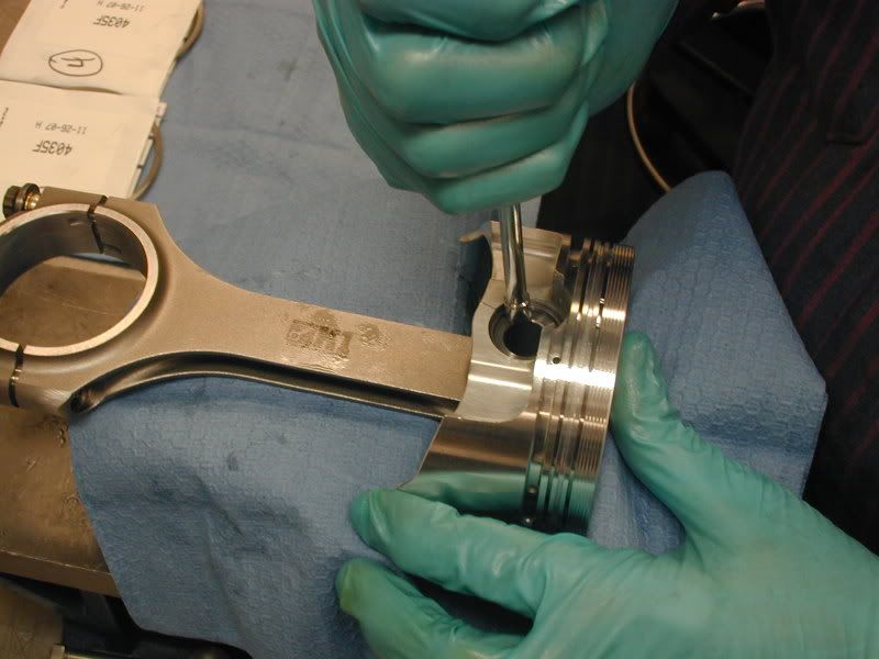
After the pin is installed the spiro locks are installed to secure the wrist pin in the piston/rod assembly:
Once all of the rods and pistons are assembled the piston rings are installed:
After all of the rings are installed on the pistons. The piston/rod assembly is put in the piston box, labeled based on the cylinder the rings were gapped for. The numbering is just an extra step that we take. The cylinders are really all identical due to our machining processes, but it is not a bad habit to have.
Now that all of our pistons and rods are assembled with rings on the pistons, we now install the assemblies into the bores of the block.
First all of the cylinders are lubricated and the rod is slid into the bore and positioned over the crankshaft:
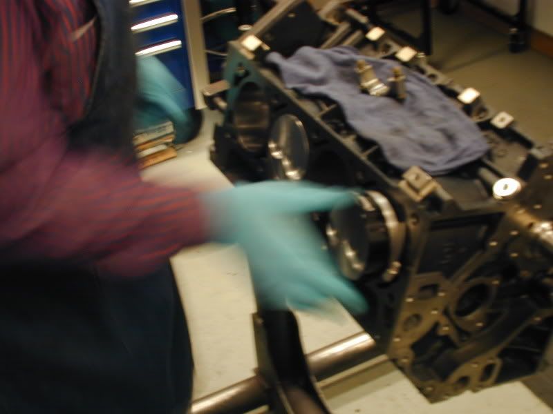
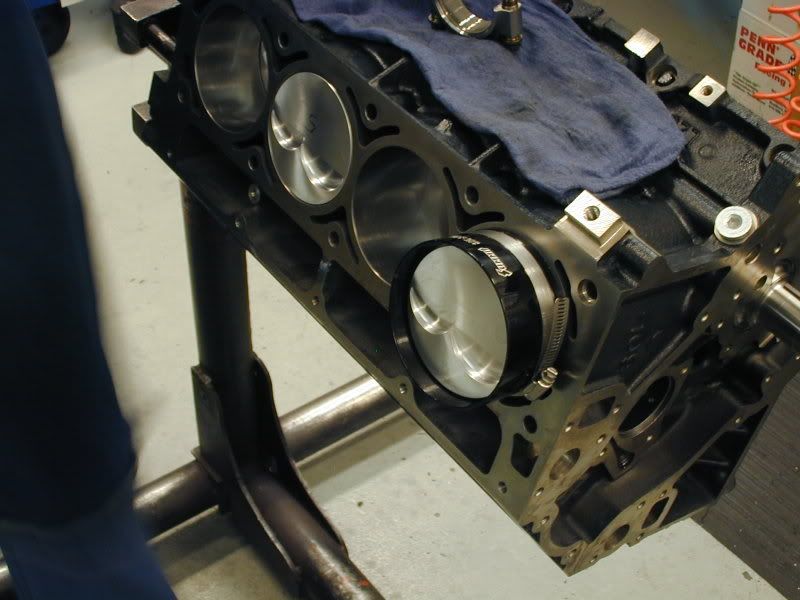
The piston is pushed into the bore by hand, once it is in the bore it is tapped in using a special hammer, the rod is guided down onto the crankshaft journal by hand onto the crankshaft. This ensures no scratching or nicking of the cylinder walls or crankshaft:
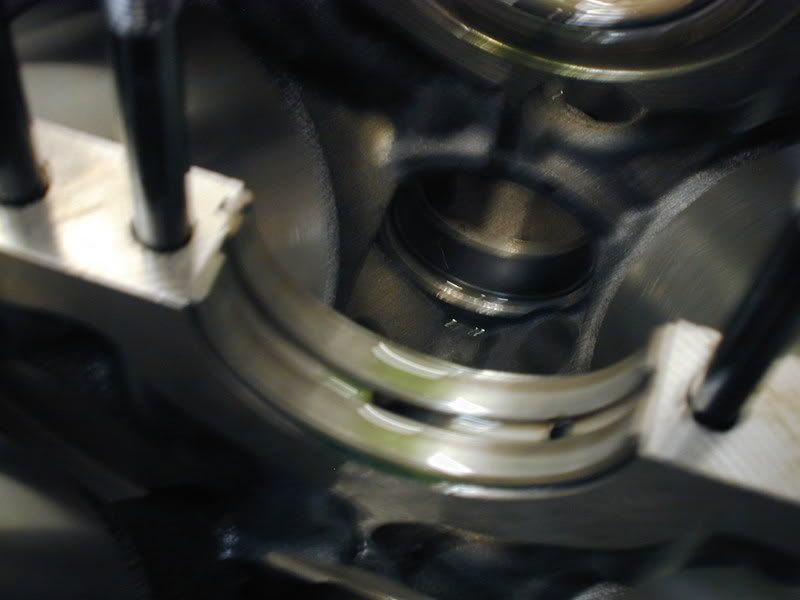
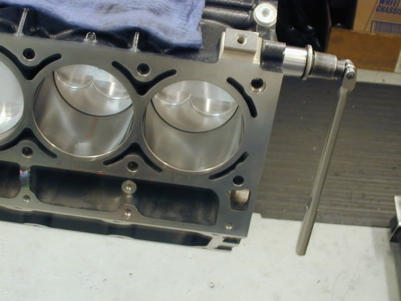
Here is a picture of a rod installed before the rod cap is installed:
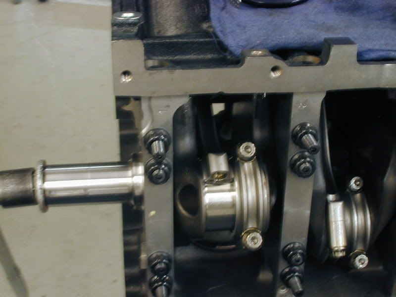
Once all of the pistons and rods are installed in the engine the rod caps are tightened and torqued to specification:
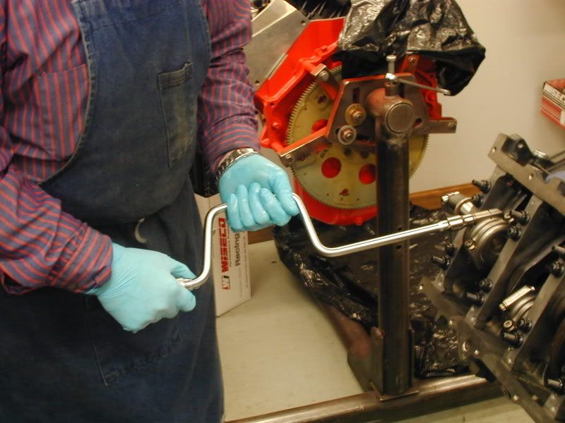
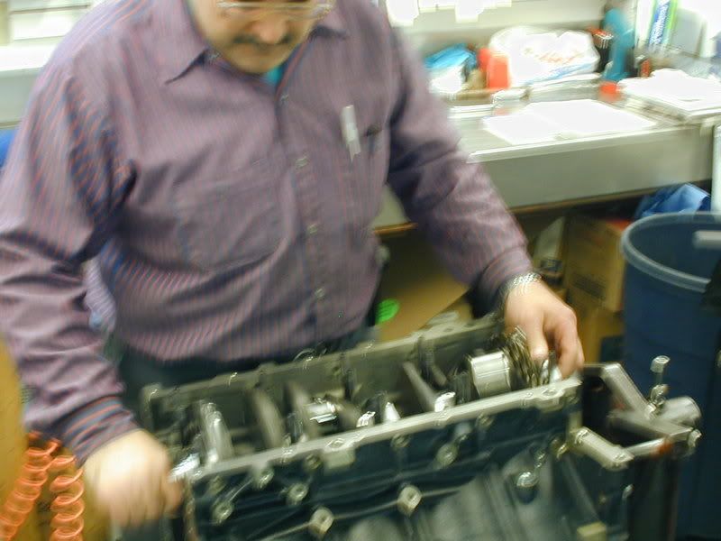
The motor is than rotated to ensure a smoother rotation and no binding:
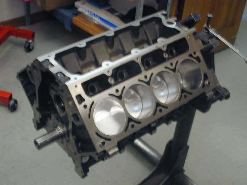
Now we have a completed short block:
This process is repeated until the desired ring gap is achieved.
As the rings are completed they are laid out and numbered based on the cylinder they will be installed on.
After the rings are filed the connecting rods and the pistons are put together:
First the rods are setup in the connecting rod vise and the bolts are loosened:
Next the rod is positioned in the piston and the wrist pin is lubricated and slid in to hold them together:
After the pin is installed the spiro locks are installed to secure the wrist pin in the piston/rod assembly:
Once all of the rods and pistons are assembled the piston rings are installed:
After all of the rings are installed on the pistons. The piston/rod assembly is put in the piston box, labeled based on the cylinder the rings were gapped for. The numbering is just an extra step that we take. The cylinders are really all identical due to our machining processes, but it is not a bad habit to have.
Now that all of our pistons and rods are assembled with rings on the pistons, we now install the assemblies into the bores of the block.
First all of the cylinders are lubricated and the rod is slid into the bore and positioned over the crankshaft:
The piston is pushed into the bore by hand, once it is in the bore it is tapped in using a special hammer, the rod is guided down onto the crankshaft journal by hand onto the crankshaft. This ensures no scratching or nicking of the cylinder walls or crankshaft:
Here is a picture of a rod installed before the rod cap is installed:
Once all of the pistons and rods are installed in the engine the rod caps are tightened and torqued to specification:
The motor is than rotated to ensure a smoother rotation and no binding:
Now we have a completed short block:
06-19-2008, 04:46 PM
#50
Banned
Thread Starter
iTrader: (4)
Join Date: Jan 2007
Location: North Ridgeville, Ohio
Posts: 539
Likes: 0
Received 0 Likes
on
0 Posts
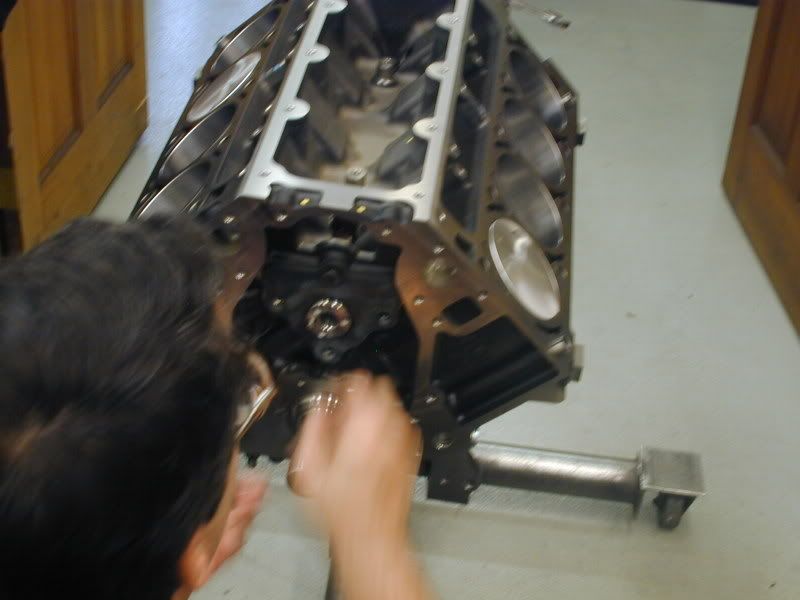
Now that the short block is assembled it is time to install the camshaft.
Thanks to Mike and Ron @ Vengeance for the recommendation on the cam. We like to work with the Vengeance guys especially when using Trickflow heads as they have a lot of real world experience with these setups in the cars and on the dyno.
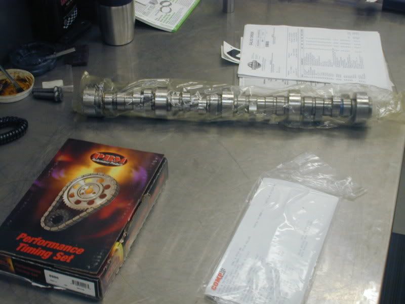
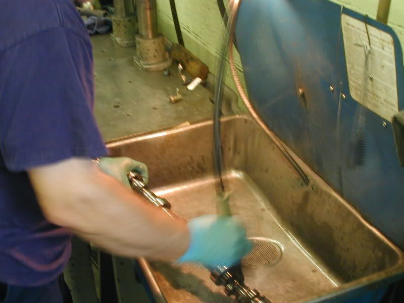
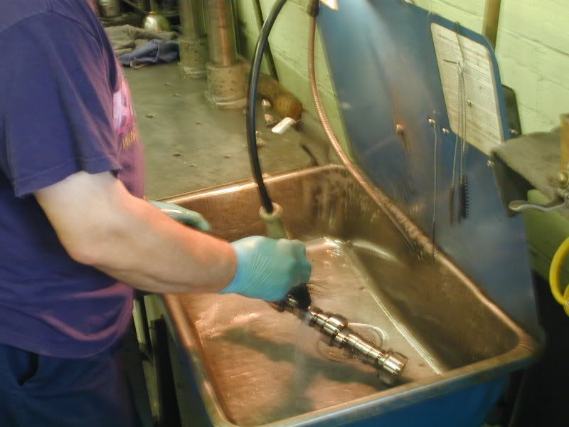
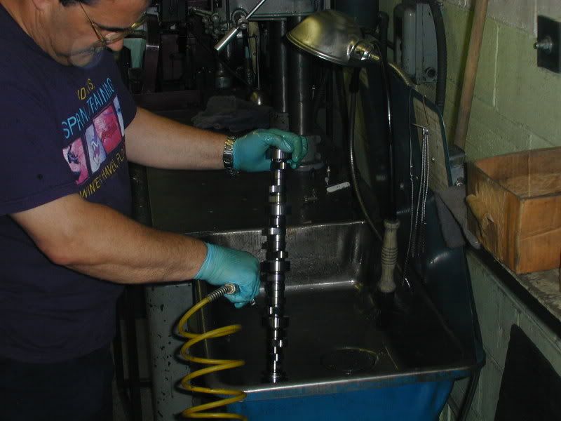
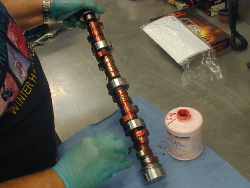
The cam is removed from the packaging and thoroughly cleaned and sprayed off with an air hose in our parts washer:
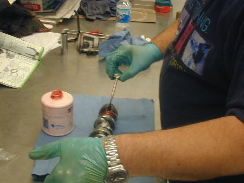
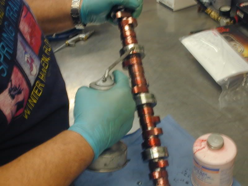
The cam is brought back into the clean assembly room and assembly lube is applied to all of the cam lobes:
Next oil is applied to the cam journals:
Than the cam is installed:
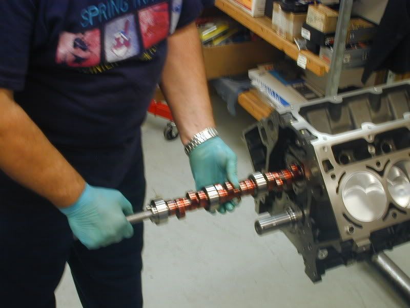
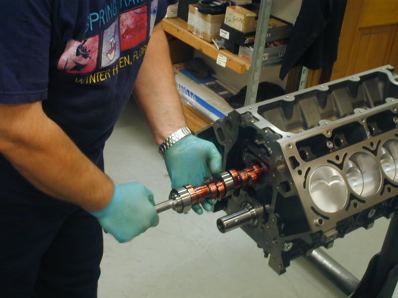
After the cam is in the block, the cam retainer plate is wiped down with a light film of oil and installed.
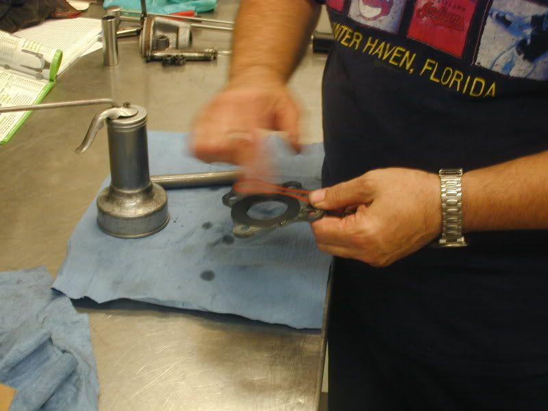
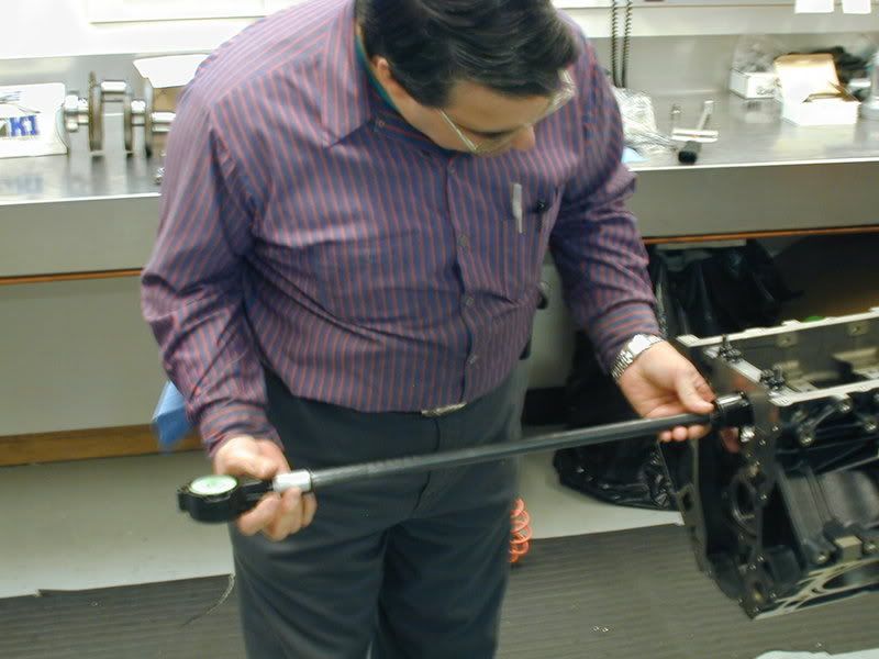
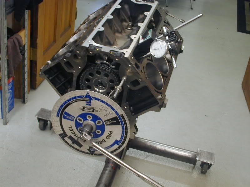
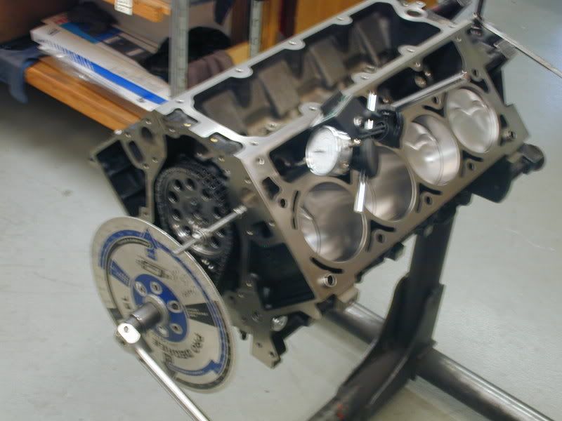
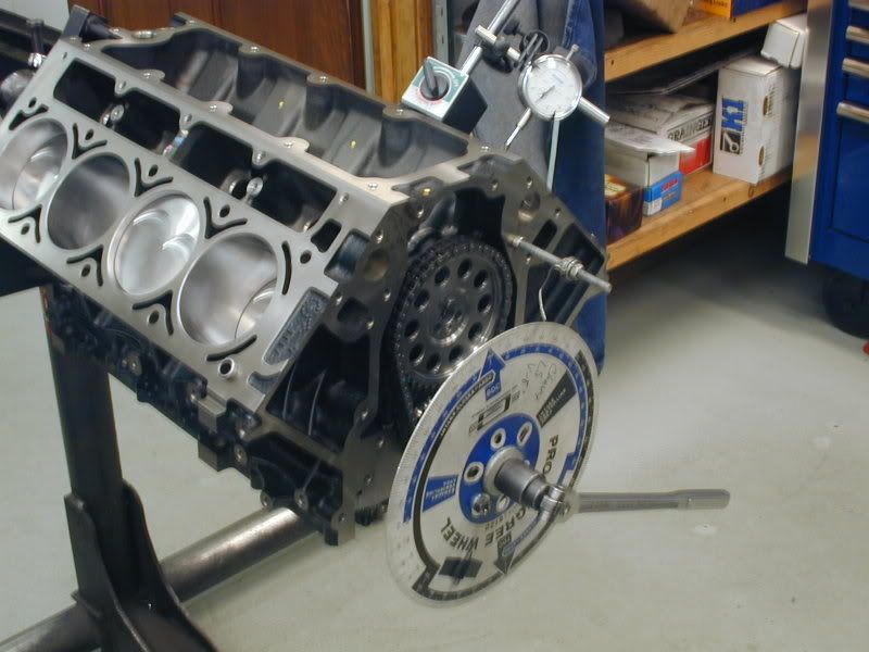
Once the cam is installed it is spun to ensure there is no binding issues with the camshaft. The timing chain is than installed and the cam is degreed in:
Now the cam is installed and degreed in. We are waiting for the heads and intake to come back from porting and we can finish assembly. STAY TUNED!
Thanks to Mike and Ron @ Vengeance for the recommendation on the cam. We like to work with the Vengeance guys especially when using Trickflow heads as they have a lot of real world experience with these setups in the cars and on the dyno.
The cam is removed from the packaging and thoroughly cleaned and sprayed off with an air hose in our parts washer:
The cam is brought back into the clean assembly room and assembly lube is applied to all of the cam lobes:
Next oil is applied to the cam journals:
Than the cam is installed:
After the cam is in the block, the cam retainer plate is wiped down with a light film of oil and installed.
Once the cam is installed it is spun to ensure there is no binding issues with the camshaft. The timing chain is than installed and the cam is degreed in:
Now the cam is installed and degreed in. We are waiting for the heads and intake to come back from porting and we can finish assembly. STAY TUNED!
07-01-2008, 04:03 PM
#52
Banned
Thread Starter
iTrader: (4)
Join Date: Jan 2007
Location: North Ridgeville, Ohio
Posts: 539
Likes: 0
Received 0 Likes
on
0 Posts
Be sure to check out our engine sale that has includes Stage II engines that receive the same machining and attention to detail as this engine (Just wont take as long waiting for new parts that have not been released to the public yet  )
)
https://ls1tech.com/forums/sponsor-sales-specials/947165-weber-racing-summer-engine-sale-also-ptc-converters-transmissions.html
)https://ls1tech.com/forums/sponsor-sales-specials/947165-weber-racing-summer-engine-sale-also-ptc-converters-transmissions.html
 07-02-2008, 08:25 AM
#56
Banned
Thread Starter
iTrader: (4)
Join Date: Jan 2007
Location: North Ridgeville, Ohio
Posts: 539
Likes: 0
Received 0 Likes
on
0 Posts
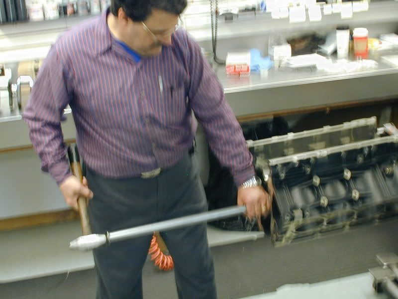
The cam bearings are actually driven into the cam bores with a, aluminum shaft and tapped with a hammer/mallett. Everything has to be lined up just right or the bore and or cam bearing can be trashed.
08-19-2008, 08:43 PM
#60
Why do gen III/IV cam bearings have a tendency to shift???
joel
Last edited by Bink; 08-19-2008 at 08:48 PM.