
Thrust Bearing Failure #2
 03-22-2013, 06:19 PM
#1
8 Second Club
Thread Starter
iTrader: (39)
Join Date: Aug 2008
Posts: 90
Likes: 0
Received 0 Likes
on
0 Posts

For the 2nd time in 2 years I have wiped out yet another thrust bearing on my turbo Iron LS motor.
Below is the link to the first bearing failure.
https://ls1tech.com/forums/generatio...g-failure.html
After the first bearings failure I chamfered the bearing corner to better oil the thrust bearing, ran 1/2" cooler lines to a large plate style cooler, removed the spacers between the flywheel and the converter to get to 3/16" clearance.
This thrust bearing lasted all season around 30-40 1/4 mile runs and about 3000 miles on the street.
- I need to verify the perpendicularity of the crank to the thrust bearing. Does anyone have a spec showing what this value should be?
 03-22-2013, 07:38 PM
#3
8 Second Club
Thread Starter
iTrader: (39)
Join Date: Aug 2008
Posts: 90
Likes: 0
Received 0 Likes
on
0 Posts
I am kicking around the idea of removing the thrust bearing and adding a four-point contact angular contact bearing to the front of the crank. I would end up adding it to the crank hub and modifying/remaking the timing cover. I just don't know if a bearing would survive in such harsh conditions!
03-22-2013, 08:00 PM
#4

For the 2nd time in 2 years I have wiped out yet another thrust bearing on my turbo Iron LS motor.
Below is the link to the first bearing failure.
https://ls1tech.com/forums/generatio...g-failure.html
After the first bearings failure I chamfered the bearing corner to better oil the thrust bearing, ran 1/2" cooler lines to a large plate style cooler, removed the spacers between the flywheel and the converter to get to 3/16" clearance.
This thrust bearing lasted all season around 30-40 1/4 mile runs and about 3000 miles on the street.
Below is the link to the first bearing failure.
https://ls1tech.com/forums/generatio...g-failure.html
After the first bearings failure I chamfered the bearing corner to better oil the thrust bearing, ran 1/2" cooler lines to a large plate style cooler, removed the spacers between the flywheel and the converter to get to 3/16" clearance.
This thrust bearing lasted all season around 30-40 1/4 mile runs and about 3000 miles on the street.
- I need to verify the perpendicularity of the crank to the thrust bearing. Does anyone have a spec showing what this value should be?
03-22-2013, 08:21 PM
#5
8 Second Club
Thread Starter
iTrader: (39)
Join Date: Aug 2008
Posts: 90
Likes: 0
Received 0 Likes
on
0 Posts
I guess I need an easier way to get the trans out without pulling the entire motor... Maybe It's time to cut an access panel into the floorboard.

Trending Topics
03-23-2013, 11:55 PM
#8
8 Second Club
Thread Starter
iTrader: (39)
Join Date: Aug 2008
Posts: 90
Likes: 0
Received 0 Likes
on
0 Posts
I had OHIO Crankshaft Weld the crank up and regrind. Only issue I saw with that repair was a sharp edge on the thrust face where the weld was just a bit thin.
I guess I will take the crank back to them for round two. Just got the motor disassembled, and everything looks good except for the thrust surface. The thrust surface on the crank is ate up pretty bad once again.
I guess I will take the crank back to them for round two. Just got the motor disassembled, and everything looks good except for the thrust surface. The thrust surface on the crank is ate up pretty bad once again.
03-28-2013, 09:03 PM
#10
8 Second Club
Thread Starter
iTrader: (39)
Join Date: Aug 2008
Posts: 90
Likes: 0
Received 0 Likes
on
0 Posts
Well the crank is out to be fixed and I have been looking in depth at the converter feed circuit and I am a little confused about the spring mod I made with the Precision Viigilanti Converter.
Here is a link to the mods they have you make for their converter.http://converter.com/book_pump.htm
The extra spring added in the converter limit valve only allows the valve to shift about .06", so I don't think it's regulating pressure to the converter properly. In addition the cross drilled hole would be directly into the high pressure side of the pump which would increase the flow.
It appears they are increasing the pressure in the converter when the torque converter is released (unlocked) which could be causing my bearing failures.
Does anyone know why they are increasing flow/pressure to the converter and why I can't just remove the extra heavy spring they had me add?
03-30-2013, 09:39 PM
#12
8 Second Club
Thread Starter
iTrader: (39)
Join Date: Aug 2008
Posts: 90
Likes: 0
Received 0 Likes
on
0 Posts
What I need someone to explain to me is how does the converter limit feed circuit (where the heavy spring mod is made) affect the converter when it is locked up...
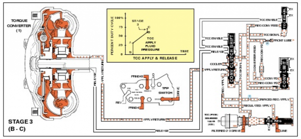
The circuit below show the converter released (Not locked up), and I agree "regulated" fluid flows out of the converter limit valve, into the converter clutch shift valve, and into the torque converter release circuit.
It then travels through the input shaft entering the converter, fills the converter, exits through the converter hub, and the flows back through the converter clutch shift valve exiting thru the trans cooler.
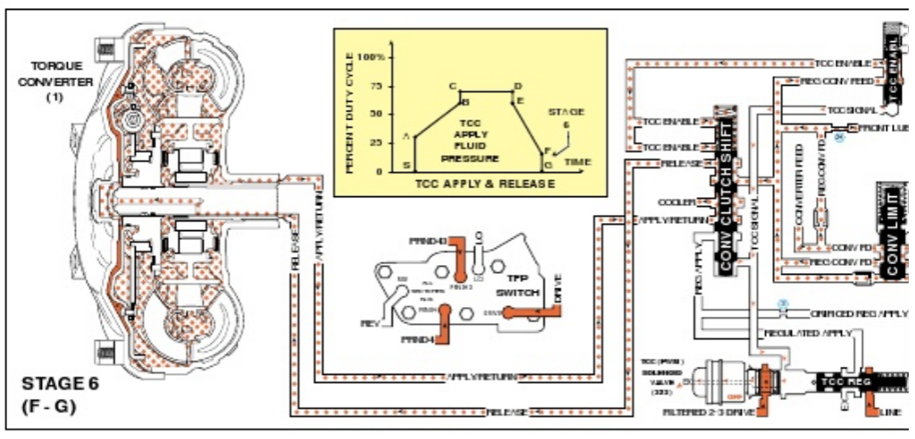
The circuit below shows the torque converter locked up. Following the converter limit valve circuit I see the "regulated" fluid flow from the converter limit valve into the converter clutch shift valve, and then is directly diverted into the trans cooler.
The pressure the torque convert sees for lock up is coming from a different circuit. The TCC (PWM) opens the TCC regulator valve, where line pressure is regulated then leave the valve. The regulated fluid flows to the converter clutch shift valve and is then sent thru the apply/return circuit to activate the TCC.
Please correct me if I'm wrong, but I don't see how bumping up the pressure in the converter limit valve help keep the TTC lock-up from slipping.
See link for detailed 4L80E schematics
http://www.scribd.com/doc/34146059/4L80E
Last edited by TransAm-Z; 03-31-2013 at 09:35 PM.