
Aluminum 454 Build
 07-07-2014, 10:35 AM
#481
TECH Enthusiast
Thread Starter
iTrader: (1)

Join Date: May 2012
Posts: 570
Likes: 0
Received 0 Likes
on
0 Posts
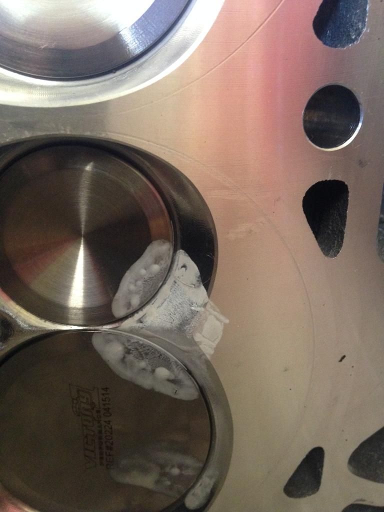
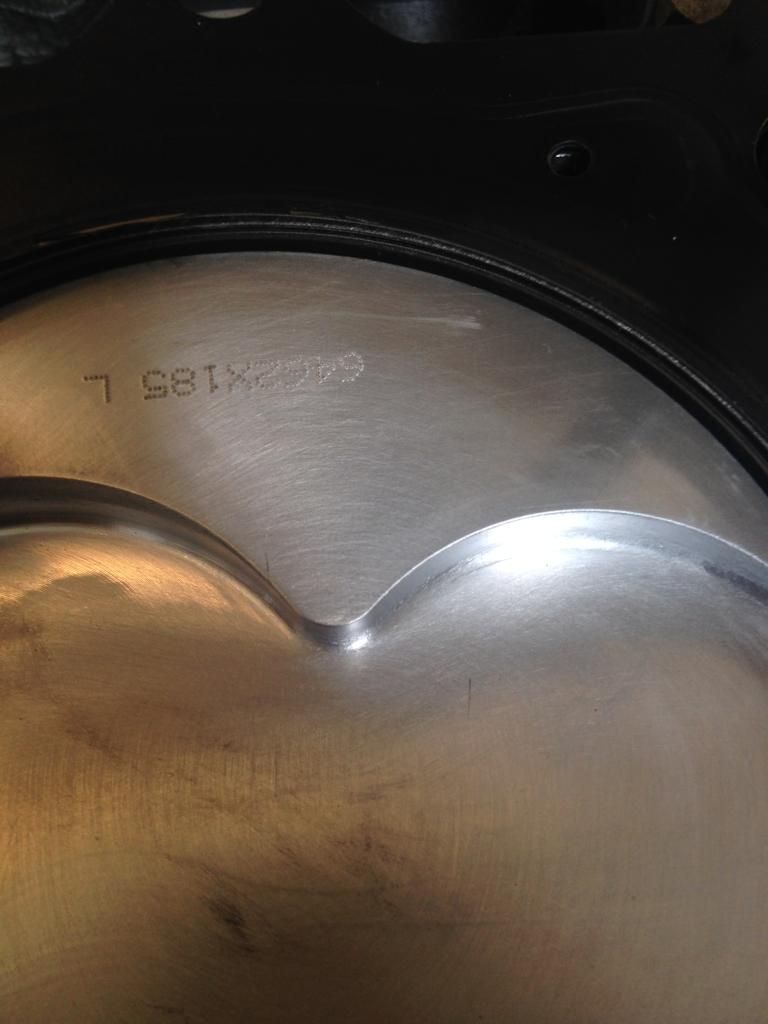
Not a whole lot has been done since the last big update....I have, however, checked piston to valve clearance using the clay method and this is what I came up with...There barely any contact between the valves and the clay, like none really to speak of, but there was one spot that the clay was compressed. You can see it in the picture, it is the point where the two valve reliefs on the piston come together. The measurement that I got right there was 0.059" of clearance. I feel like that is safe, expecially since the piston is the only thing moving at this contact point, seeing as where it contacts the head isn't in motion...let me know what ya'll think...
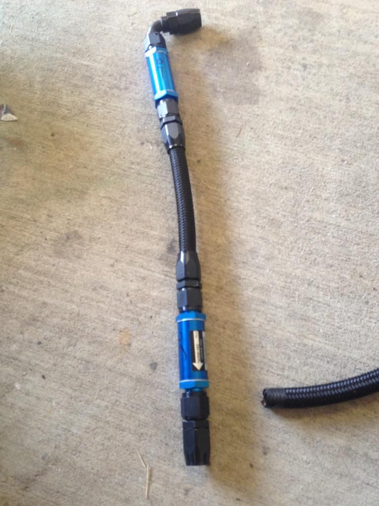
I also got some small plumbing stuff done like tying the fuel rails together, tying the vacuum rails together, and getting my fuel filters connected with each other....
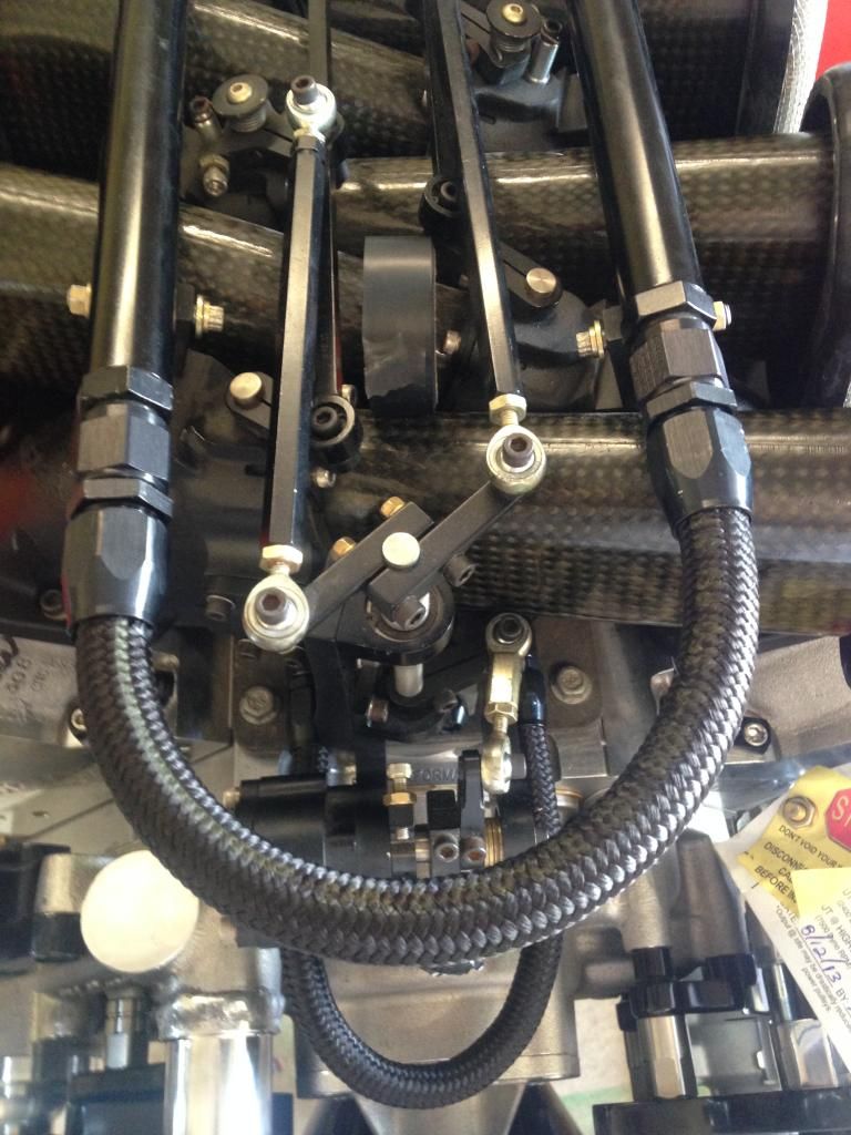
The fuel filters are an 85micron followed by a 35micron filter, both with -8AN fittings on each end...


I also got some small plumbing stuff done like tying the fuel rails together, tying the vacuum rails together, and getting my fuel filters connected with each other....

The fuel filters are an 85micron followed by a 35micron filter, both with -8AN fittings on each end...

 07-07-2014, 10:55 AM
#482


IIRC…………. the preferred clearance for P2V is .100 exhaust and .080 for the intake. Did you take any pics of the clay as it was deformed?
 07-07-2014, 10:58 AM
#483
TECH Enthusiast
Thread Starter
iTrader: (1)
Join Date: May 2012
Posts: 570
Likes: 0
Received 0 Likes
on
0 Posts
No I forgot to take a pic of the clay prior to taking it off of the piston...I do plan on checking it again though just to be 100% sure, so I will take a pic of it then...
07-07-2014, 12:54 PM
#484
I always put a strip of clay across the valve reliefs on the piston, bolt the head down, turn crank a few times, remove head, cut each piece of clay and check thickness.
<.100" intake/.080 exhaust
EDITED
<.100" intake/.080 exhaust
EDITED
Last edited by SSSTANG#1; 07-07-2014 at 01:01 PM.
07-07-2014, 07:47 PM
#485
TECH Enthusiast
Thread Starter
iTrader: (1)
Join Date: May 2012
Posts: 570
Likes: 0
Received 0 Likes
on
0 Posts
That is basically what I did, but I only used one piece of clay across both valve relievs, and the valves barely even touched the clay....I am going to check again though because I was suing the hyd. lifters with the dual valve springs, so i want to check using the checker springs so the lifters don't collapse
 07-08-2014, 11:05 AM
#487
TECH Enthusiast
Thread Starter
iTrader: (1)
Join Date: May 2012
Posts: 570
Likes: 0
Received 0 Likes
on
0 Posts
Yeah I checked with the pushrods I got from you...The PTV isn't whats at 0.059" it is the piston to head clearance....I didn't even bother with measuring the clay where the valves hit it because it only compressed it like 0.05"...I had about 0.25" on both int. and ext. valves to the piston....
 07-08-2014, 10:25 PM
#494
TECH Enthusiast
Thread Starter
iTrader: (1)
Join Date: May 2012
Posts: 570
Likes: 0
Received 0 Likes
on
0 Posts
had a good convo with Martin today and got some stuff figured out...also I am trying to work something out with Larry Meaux and Allan Futral to get this engine broken in and tuned on Larry's dyno cell....Hopefully I will get some more info on this in the next couple of days.
07-16-2014, 12:01 PM
#495
TECH Enthusiast
Thread Starter
iTrader: (1)
Join Date: May 2012
Posts: 570
Likes: 0
Received 0 Likes
on
0 Posts
Ok so it looks like I will actually be taking the engine to LME in Houston to get it broken in and tuned...I should be getting it there some time in August, fingers crossed...
I got the rear wheels in for the car....I think they are going to look sick....
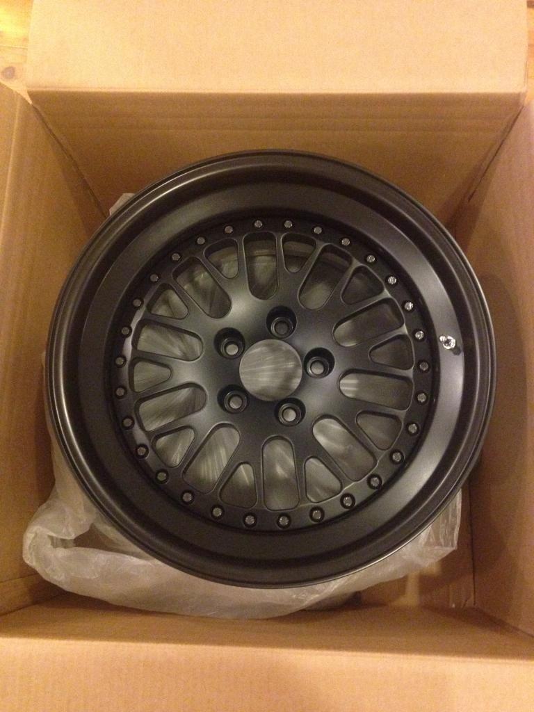
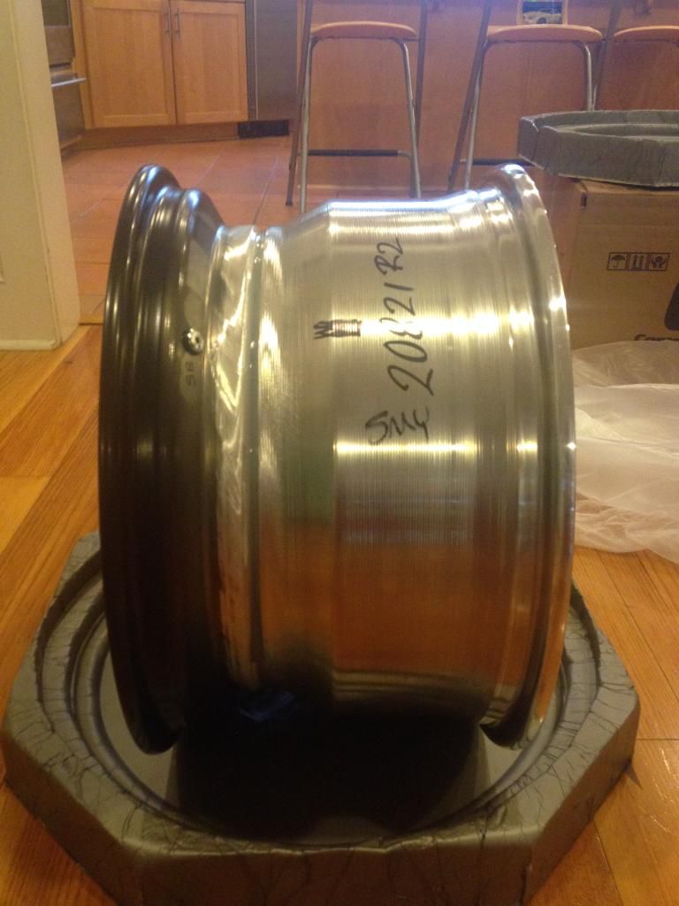
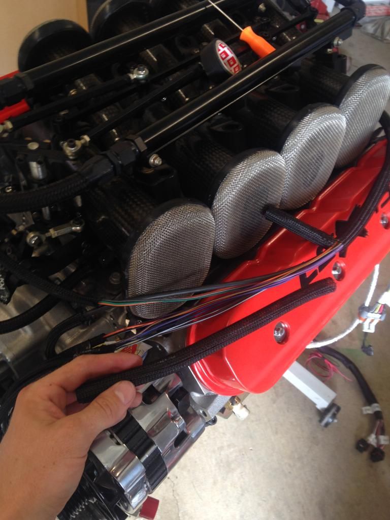
Also this past weekend I was able to get some stuff done with the wiring harness that came with the holley dominator. I de-loomed a few sections so I could clean up the under hood appearance of the engine...I have the IAT, TPS, CPS, and CTS all running under the intake and coming out the front to their respective sensors...I also ran the injector harness up from under the intake, so the only part of it you see are the clips going on to the injectors....Now I am in the process of getting the rest of the wiring figured out, as well as starting in on the plumbing of the PS lines, coolant lines, fuel lines, brake lines, and pcv lines....I am hoping to get most of this done in the next few weekends so when the engine comes back from LME I can sit it down in there and hook it up, and possible drive the car before it goes off to paint and body...
I got the rear wheels in for the car....I think they are going to look sick....


Also this past weekend I was able to get some stuff done with the wiring harness that came with the holley dominator. I de-loomed a few sections so I could clean up the under hood appearance of the engine...I have the IAT, TPS, CPS, and CTS all running under the intake and coming out the front to their respective sensors...I also ran the injector harness up from under the intake, so the only part of it you see are the clips going on to the injectors....Now I am in the process of getting the rest of the wiring figured out, as well as starting in on the plumbing of the PS lines, coolant lines, fuel lines, brake lines, and pcv lines....I am hoping to get most of this done in the next few weekends so when the engine comes back from LME I can sit it down in there and hook it up, and possible drive the car before it goes off to paint and body...
 07-17-2014, 09:14 AM
#500
TECH Enthusiast
Thread Starter
iTrader: (1)
Join Date: May 2012
Posts: 570
Likes: 0
Received 0 Likes
on
0 Posts
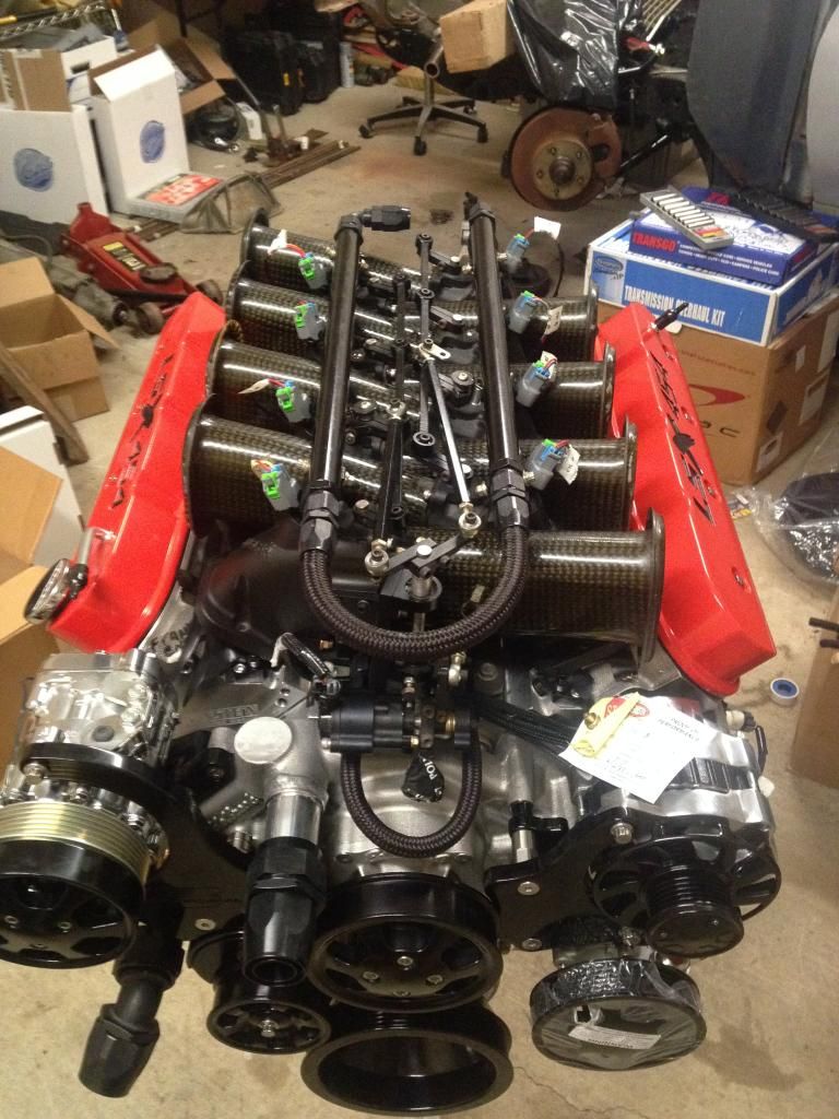
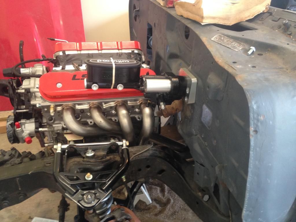
Here are some pics of the wiring harness, sort of before and after...I didn't take as many pictures as I wanted to, but you can see in the picture of the engine with the intake on how clean the harness will look....
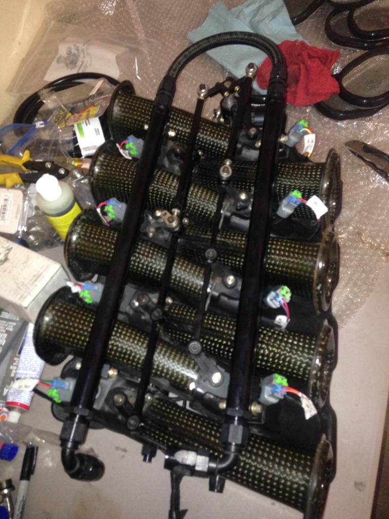
de-looming the top half of the harness...
Injector harness before
and after
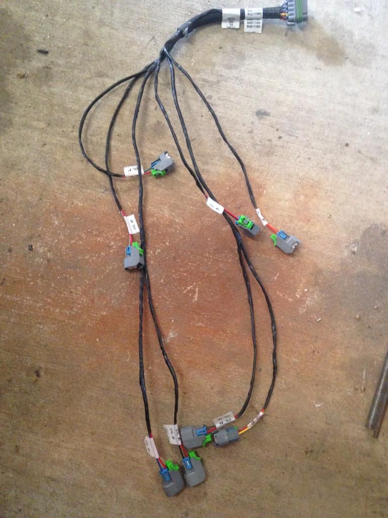
and installed
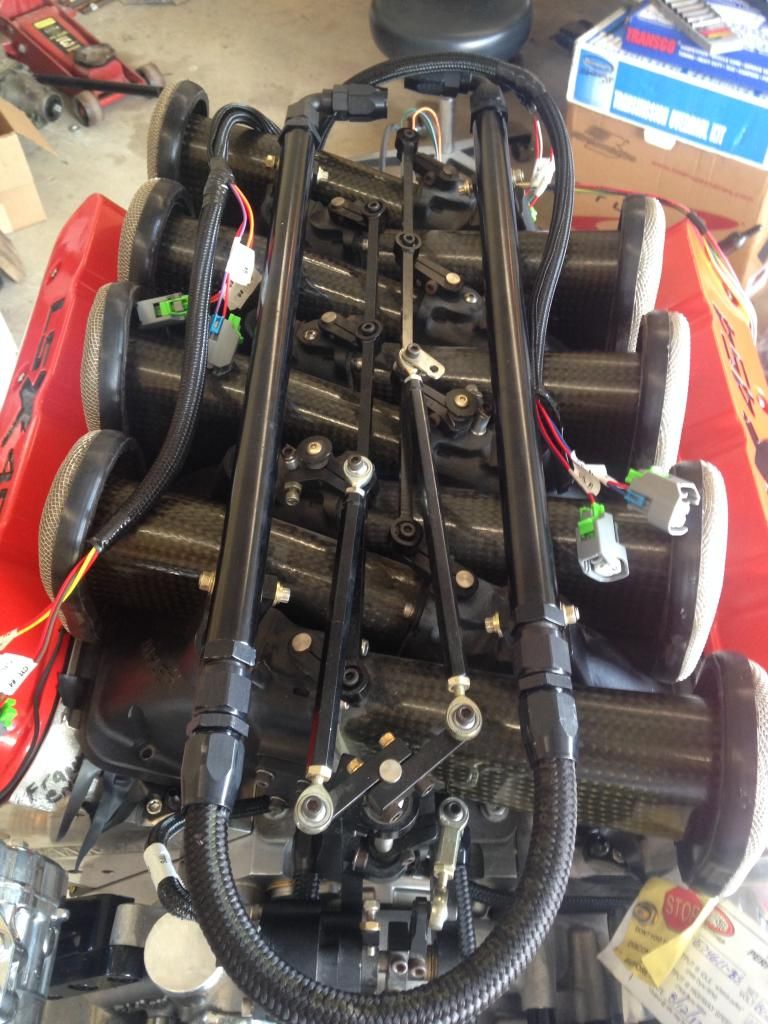
and here is the engine with the complete harness installed, minus the alt. wire and the A/C wire...The Map and IAC will be mounted remotely and out of sight...The coils will be located up on the fire wall so they won't clutter up the engine too much more...
while I was messing with the wiring harness I was trying to figure out how and where to mount my intake air temp sensor....this is what I came up with...this is on the front of the intake...
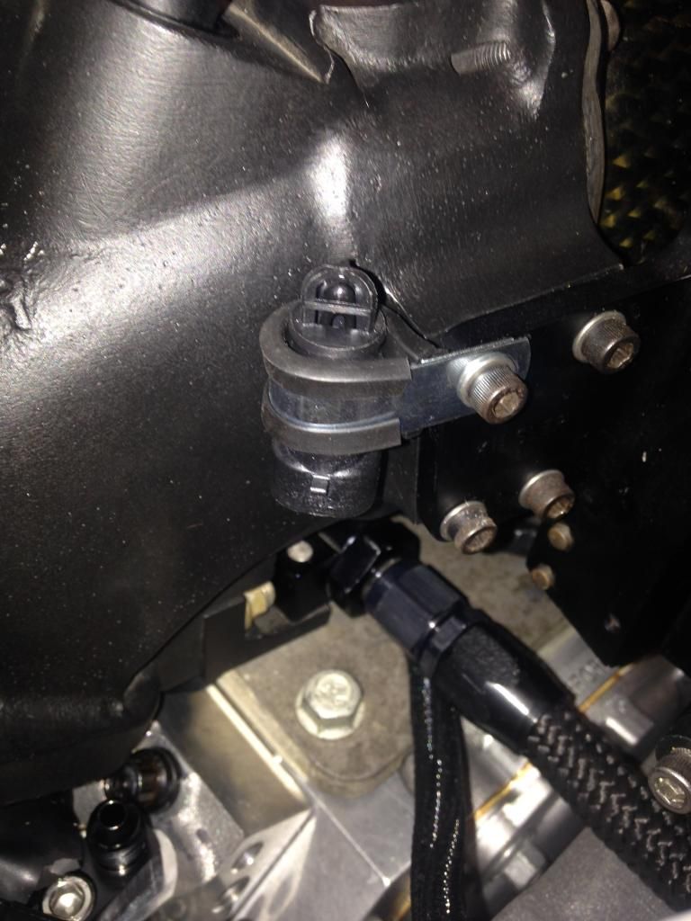
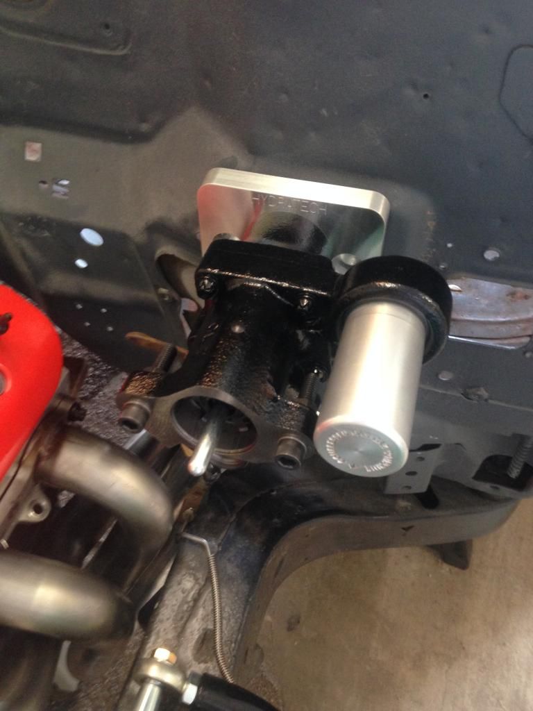
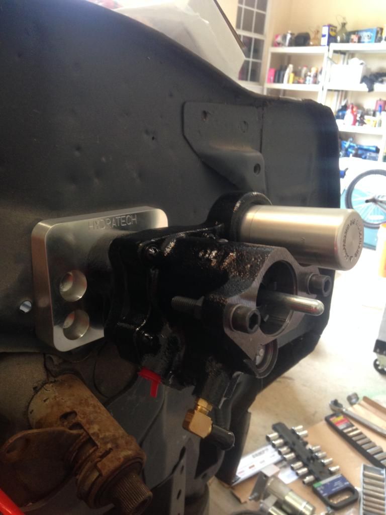
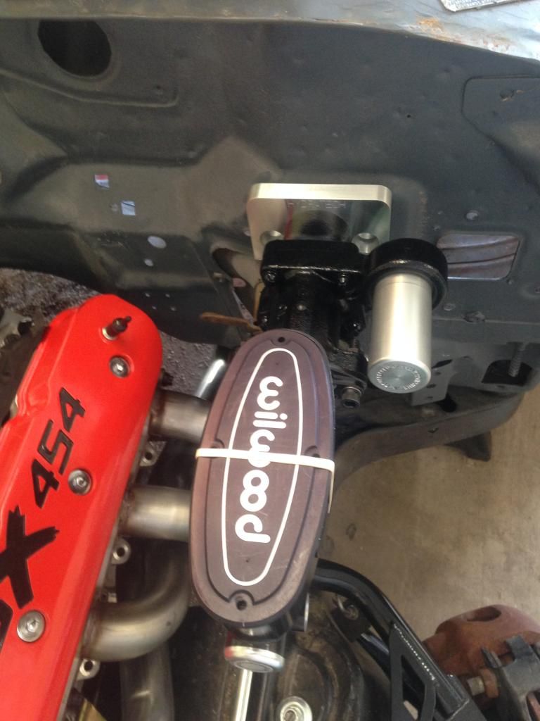
I also got my brake booster and master cylinder installed for the time being...
de-looming the top half of the harness...

Injector harness before

and after

and installed

and here is the engine with the complete harness installed, minus the alt. wire and the A/C wire...The Map and IAC will be mounted remotely and out of sight...The coils will be located up on the fire wall so they won't clutter up the engine too much more...

while I was messing with the wiring harness I was trying to figure out how and where to mount my intake air temp sensor....this is what I came up with...this is on the front of the intake...

I also got my brake booster and master cylinder installed for the time being...


