When you click on links to various merchants on this site and make a purchase, this can result in this site earning a commission. Affiliate programs and affiliations include, but are not limited to, the eBay Partner Network.
I have loved watching this since you first started it. Its a build thread I could only dream of lol. I have a couple questions though. First, how do you like that oversized tilt pin? Did it tighten up the normal wobble that the tilt wheels have in these cars? Also, where did you find a new lower shift boot? I have been looking all over the place for one because mine is pretty hacked up.
Also, be careful with the MGW and reverse. Mine would flex the console every time and I even had to trim some of the plastic inside just to get it to go into reverse.
Thank you for the kind words. Yes, I too have dreamed of doing a build like this ever since I was a teenager. The biggest thing I ever did (automotive-wise) before this, was the suspension upgrade to Strano stuff and Koni yellows over 3 separate weekends. I had to, as it was my daily driver. Now that I went and bought an S10 to get to work in, well, here we are 2.5 years later. Your questions are all quite relevant to things I have been working on or thinking about recently.
1) I installed the oversize tilt pin some months back, and it felt firmed up for a second, but after I put the wheel back on yesterday, it was just as bad as before--maybe worse. I bottomed out a �” hex head screw into the pin, put a matching socket on a 3/8” extension, and proceeded to beat it in with a sledge hammer. It seated better this time. The 1-to-7 O'clock rock is basically gone. There is a much more minor rock I can now feel on the other pin, but it isn't substantial enough to warrant tearing half the column apart. I do have a second pin though, so when I do eventually have to replace a blinker unit or something, I will get that side too. I hope that the reason the problem returned is not that the oversize pin backed out on its own, but rather that I did not hammer it in deep enough the first time. If it backs out again, I'm putting a hole in the perimeter of it and tapping it with a fastener directly to the steering column.
2) The shift boot is reproduction from Hawks, part number HT10267518. I'm wary of reproduction parts from Hawks, as the plastics they use for things like the airbox and interior parts are garbage. The boot is well made though, as is their 1LE style shifter.
3) I cannot shift into reverse, even if I try to strong-arm it. My car has no battery in it, so I think the issue is that the reverse lockout/assist solenoid is unpowered. Maybe the T56 Magnums are simply that way. You may be right, I may have to trim the console once I power things up. Hopefully the wiring I ran for the lockout solenoid works correctly. That could be a real pain to have to work around until it’s sorted out.
There will be a bonus thread much later on when the car is mostly done, with the steering wheel. I will say that I got the thing TIG welded yesterday, and it’s solid. Cosmetically it still needs a lot of work though, so I won’t start that one until the final product is ready.
Thanks for the replies. Would you say that it was worth the effort for the larger pin? In some ways it kinda seems like maybe it wasn't.
Thanks for the part number as well, I even looked on their website and somehow completely missed that. I also upgraded to their 5th gen shift **** setup. I went with the black suede with red stitching version on my factory Hurst base. I love everything about it except how far back it sits while in the even number gears. It basically touches the back edge of the console but its never hurt anything and any short stick on a Hurst will do that.
Unless the magnum uses a different strength spring for the reverse lockout (which I doubt since it appears to be the same part as a regular t56), you should be able to strong arm it in. You really have to muscle it though. I did it for about 4 years when my lockout went bad. Or you could pull it off real quick to test the clearance with the center console as the lockout is only held on by a couple bolts and a connector. Its on the drivers side at the top under where the shifter mounts BTW. Mine would shift most of the way over to reverse but wouldn't go far enough to let me engage it without trimming the console which is one of several reasons I ended up selling the MGW and going back to stock.
Yes, the larger pin was definitely worth it. With the suspension I mentioned earlier and the non-sport seats, I had been hanging off the steering wheel for too long. I also always flip down/up the wheel when I get in/out of the car. The issue was becoming quite annoying at best, and dangerous at worst. The whole thing only took a few hours, and if I had to do it again, it would probably take half the time. The only part that was a serous PITA, was unscrewing the tilt lever, as that stick was in there with Loctite or something. It remains to be seen if the pin can back itself out again, but one way or another I will make it work. For now, it seems to be doing its job. I also switched to racing seats a few years back to better bolster the high G-forces.
Good idea with the removing the lockout solenoid to test. If it's not too much of a pain, I may do just that. I don't mind trimming a bit of the console, so long as it is not visible later. Hopefully that would be hidden by the upper console. Issues could also be that the transmission is brand new, so the reverse gear may be a little stuck until it gets turning, or it could be the powerful centering springs on the MGW combined with the Magnum's built-in self centering which the stock transmission did without.
I guess some new pins are in order for me then. My old third gen had the problem so bad that I had to push the wheel down to turn the brights on and off so I don't want my current car to get that bad. Plus I am tired of it just feeling broken lol.
Pulling the lock out is really easy, like I said just 2 bolts and the wiring connector. You should be able to get to it without pulling the trans as well but I can't remember for certain. As for the trimming, it was all on the inside of the console and you couldn't see anything after it was put together. I probably couldn't even tell you now where I cut without looking really hard at mine lol. But, even after cutting as much as I felt like I could, the shifter still pushed against the console and caused it to flex which I feel like made it harder to engage reverse. I would for sure check it out before you fall too much in love with the MGW. My other big complaint with the MGW was how hard it was to shift 5-6 under normal driving. The centering spring in it was so stiff that I had to flip my hand upside down and push away from me as I went into 6th to make sure I didn't go 5-4. That and 3rd was always a crap shoot compared to the stock hurst base. With it I can hit it every time, but I missed 2-3 a LOT more often with the MGW and even an occasional 3-4 with it. I just never liked it if you can't tell lol.
Some overdue updates (continued from the heat shielded fuel lines above):
Removed factory heat shielding on underhood fuel lines to separate the two.
Installed Velcro-sealed, individual heat wrap.
Installed Velcro-sealed, individual heat wrap.
Got the JAAM Ram Air kit foam seated to the airbox after leaving the hood closed for a bit.
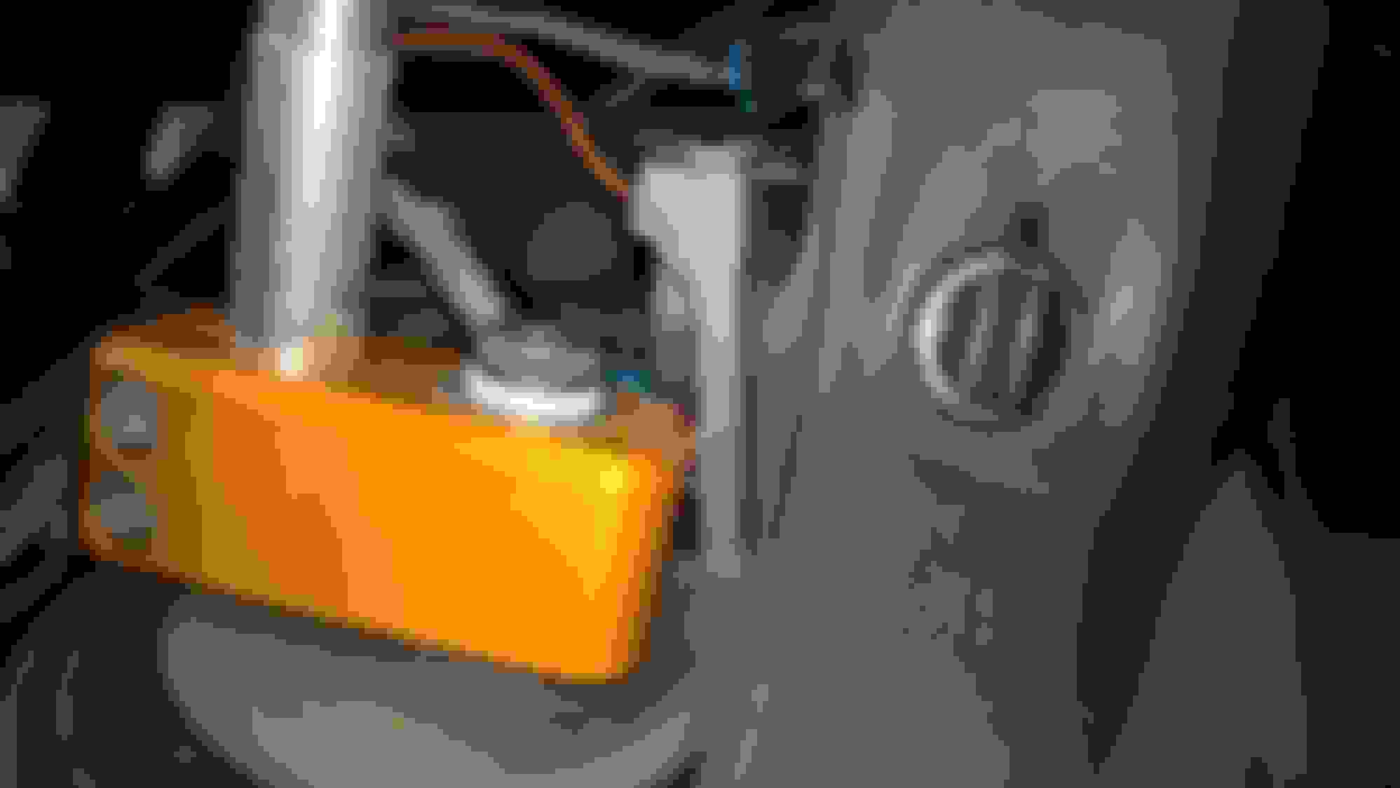
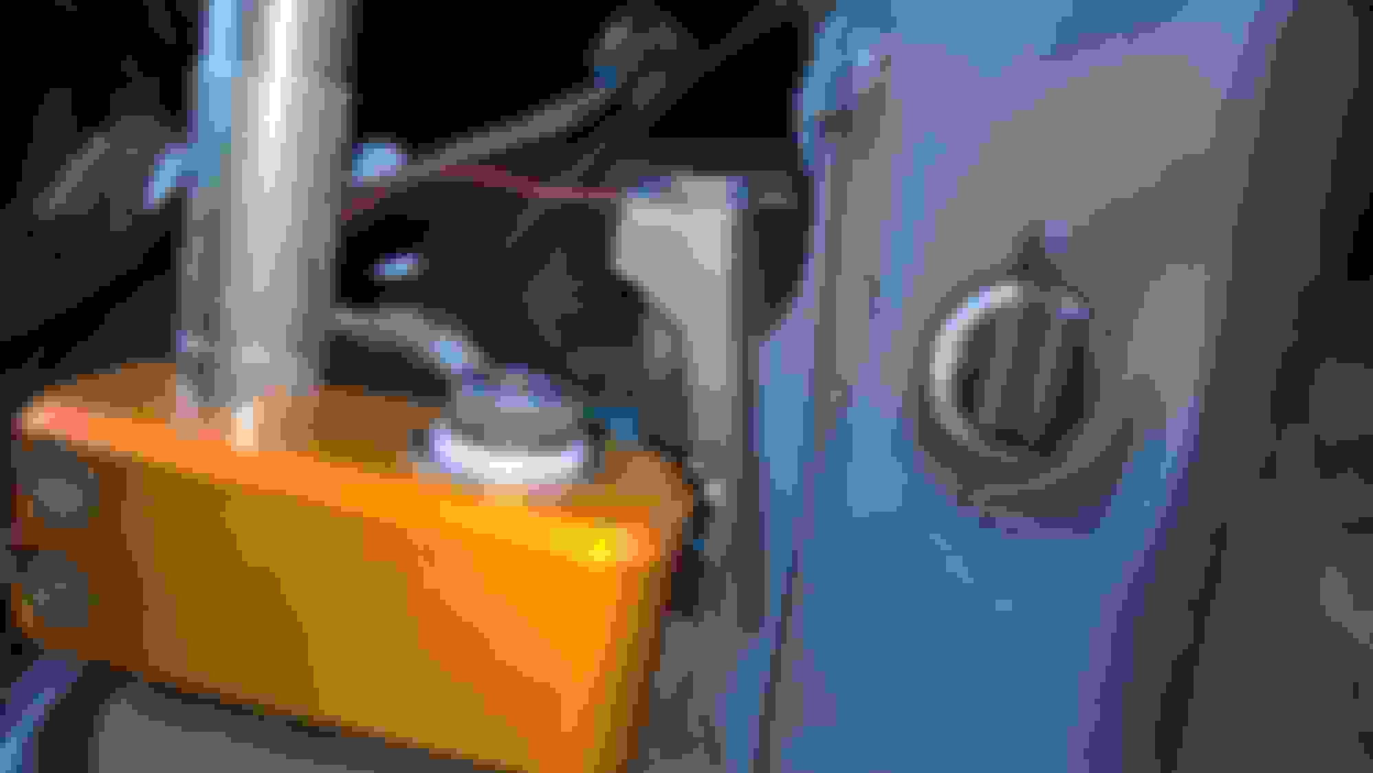
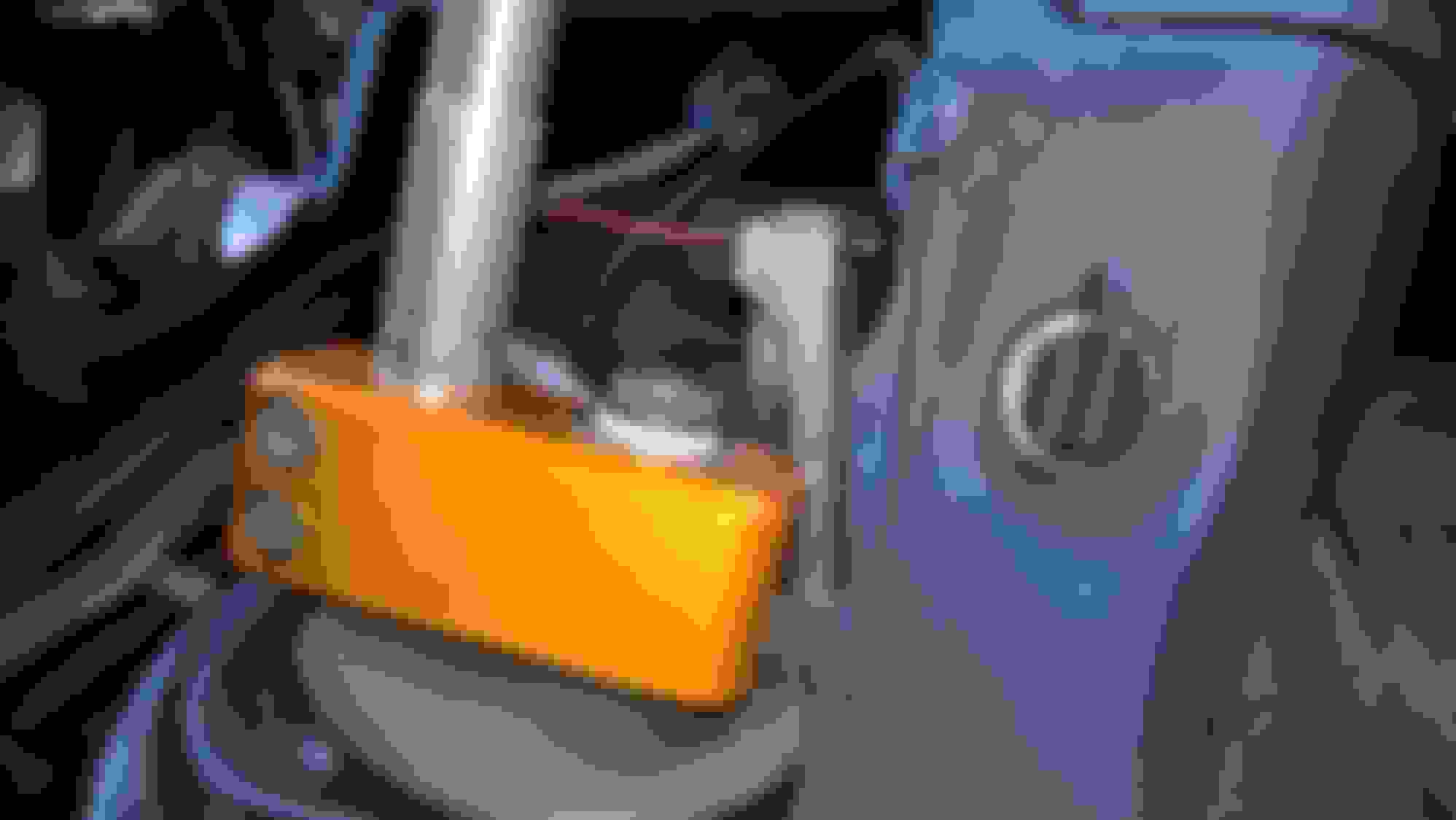
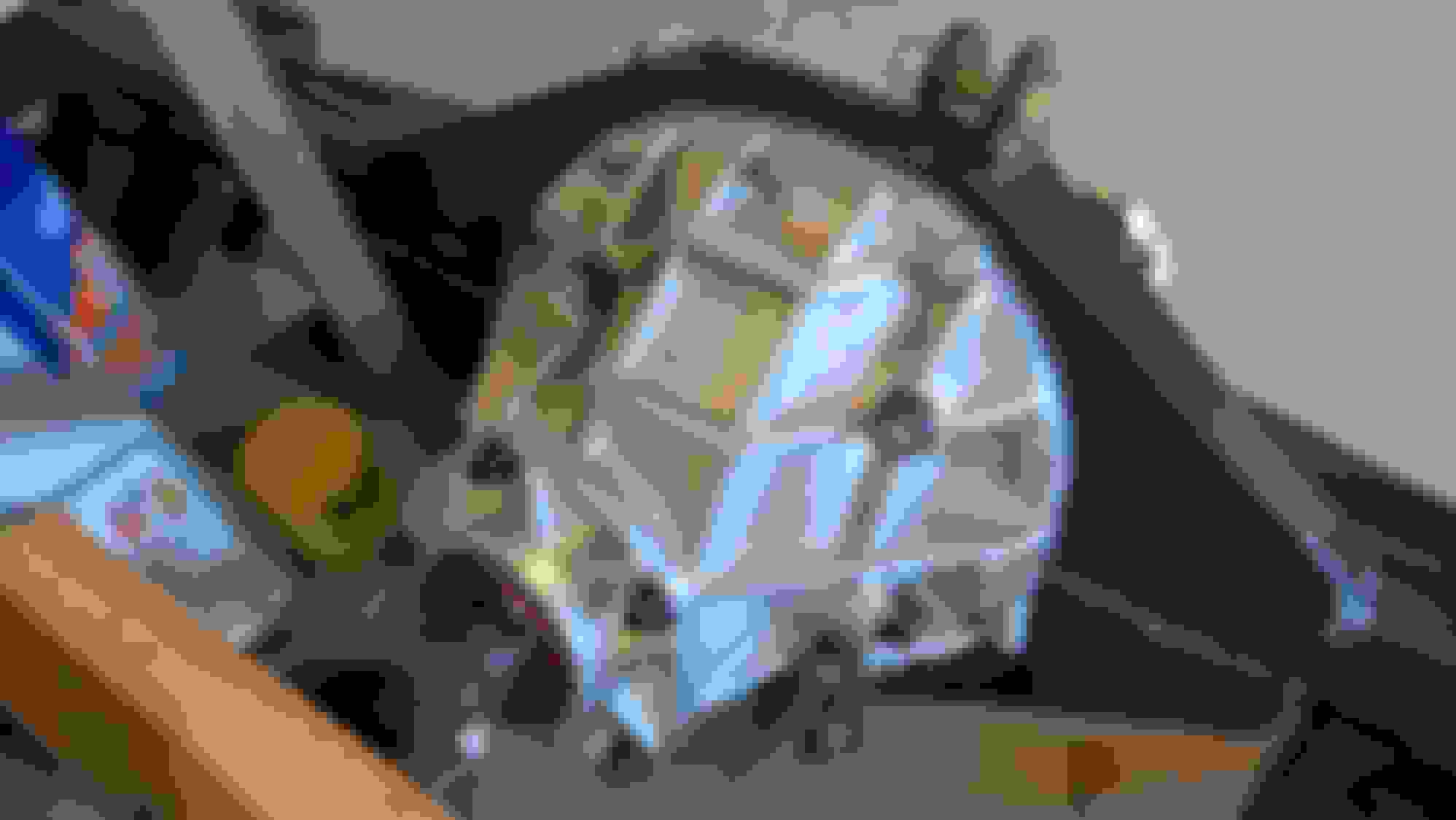
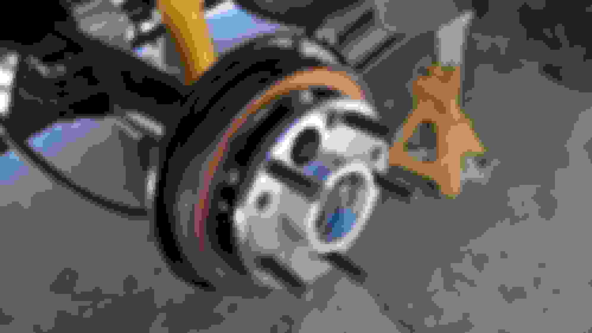
Here are some pics of how to hammer in the steering column tilt pin. Place a short hex-head machine screw into the hole. Get a matching 3/8" drive (or larger) socket and an extension, and hammer that thing in with a small sledge. Beat it like it owes you money.
Here are some pics of how to hammer in the steering column tilt pin. Place a short hex-head machine screw into the hole. Get a matching 3/8" drive (or larger) socket and an extension, and hammer that thing in with a small sledge. Beat it like it owes you money.
I took the advice of 1bdbrd, and pulled the reverse lockout solenoid from the trans. There is no way to overpower this thing as far as I can tell. Once it was out, it is almost impossible to grab 5th instead of reverse. The shifter does hit the inside of the console a little bit, so I clearanced it to stop the wobbling console.
I took the advice of 1bdbrd, and pulled the reverse lockout solenoid from the trans. There is no way to overpower this thing as far as I can tell. Once it was out, it is almost impossible to grab 5th instead of reverse. The shifter does hit the inside of the console a little bit, so I clearanced it to stop the wobbling console.
I took the advice of 1bdbrd, and pulled the reverse lockout solenoid from the trans. There is no way to overpower this thing as far as I can tell. Once it was out, it is almost impossible to grab 5th instead of reverse. The shifter does hit the inside of the console a little bit, so I clearanced it to stop the wobbling console.
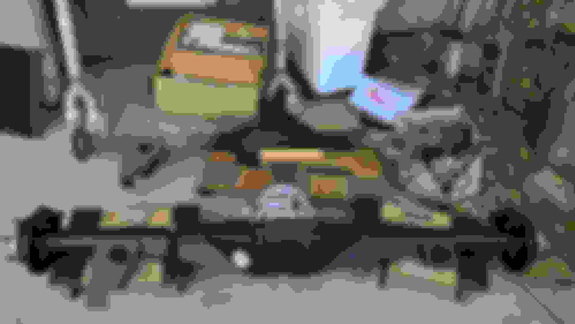
August 2018: Finally got my MWC 9" rear axle with watts link, long torque arm, and subframe connectors. I ordered this on Black Friday 2017 and gave them my final dimensions March 2018.
Box was a little "forked," but contents look okay.
Box was a little "forked," but contents look okay.
MWC 9" with Powertrax Grip Pro limited slip, 3.25 gears, HD-Pro aluminum center section, 35 spline axles, 4-channel ABS
MWC 9" with Powertrax Grip Pro limited slip, 3.25 gears, HD-Pro aluminum center section, 35 spline axles, 4-channel ABS
MWC 9" with Powertrax Grip Pro limited slip, 3.25 gears, HD-Pro aluminum center section, 35 spline axles, 4-channel ABS
MWC 9" with Powertrax Grip Pro limited slip, 3.25 gears, HD-Pro aluminum center section, 35 spline axles, 4-channel ABS
Unfortunately, I have been struggling with axle fitment issues for two months now, so direct "bolt-in" it is not. To MWC credit, they have stood behind the axle with good customer support. So don't think I am merely venting my frustrations at them. I understand that this is a custom sheet metal axle that fits a Ford design into an F-body. I did anticipate that there would be some adjustments necessary. I was really not prepared for how much work would be involved in getting the axle in.
1) The factory trailing arms don't fit. One side was close and only required light grinding, the other side required grinding about 1/8" off the bushing to fit between the brackets. The provided grade 8/10.9 hardware is too large to fit through the bushing as well. I had to reuse the factory bolts. You could say, "This requires an aftermarket part," but mixing aftermarket parts often causes more problems.
2) The mounting hole for the lower shock mount is too small. Way too small. Even the largest drill bit I have wasn't big enough, so I had to open it up with a Dremmel grinder.
3) Lower torque arm bracket is welded crooked. Had to grind off about 1/16" of metal to fit. As you can see, MWC own torque arm eyelet fits from one side, and then gets stuck at the bottom. No, this was not just powdercoating I removed.
3) Lower torque arm bracket is welded crooked. Had to grind off about 1/16" of metal to fit. As you can see, MWC own torque arm eyelet fits from one side, and then gets stuck at the bottom. No, this was not just powdercoating I removed.
Axle finally in place somewhat
4) The watts link bolts are too small on one side, and too large on the other. The factory bolts are too fat to fit through the watts link bracket. More drilling.
4) The watts link bolts are too small on one side, and too large on the other. The factory bolts are too fat to fit through the watts link bracket. More drilling.
4) The watts link bolts are too small on one side, and too large on the other. The factory bolts are too fat to fit through the watts link bracket. More drilling.
5) Torque arm forward mount bracket nearly hits the VSS. I was able to clock the sensor to a different angle with MWC advice.
5) Torque arm forward mount bracket nearly hits the VSS. I was able to clock the sensor to a different angle with MWC advice.
5) Torque arm forward mount bracket nearly hits the VSS. I was able to clock the sensor to a different angle with MWC advice.
+ The watts link actually connected up pretty easily (other than the passenger side of the bracket). So they get a point for that one.
6) Wheel speed sensors hit the axle tube flanges. I ground a flat spot in each one to allow insertion without destroying the sensor.
6) Wheel speed sensors hit the axle tube flanges. I ground a flat spot in each one to allow insertion without destroying the sensor.
- I hope I don't encounter the dreaded wheel-speed ABS issues others have. If I do, I will attempt to alter the depth of this sensor to better match the factory one.
+ Parking brakes installed. This is easier than stock, actually. Point to MWC.
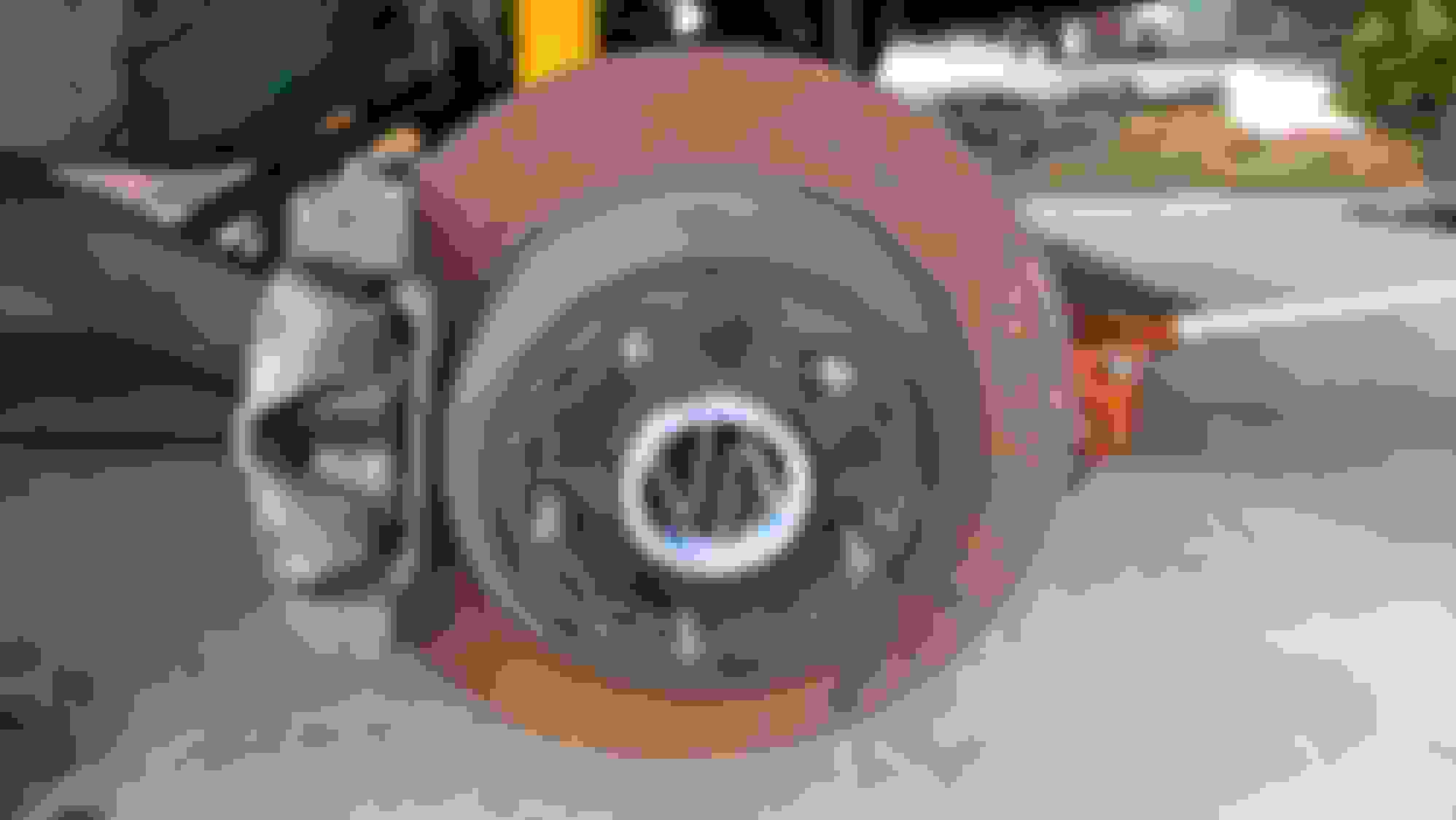
Installed rear brakes
7) Factory brake lines don't come anywhere close to fitting. I completely rebent my factory brake lines (and chewed up the fresh paint in the process).
7) Factory brake lines don't come anywhere close to fitting. I completely rebent my factory brake lines (and chewed up the fresh paint in the process).
7) Factory brake lines don't come anywhere close to fitting. I completely rebent my factory brake lines (and chewed up the fresh paint in the process).
7) Factory brake lines don't come anywhere close to fitting. I completely rebent my factory brake lines (and chewed up the fresh paint in the process).
8 + 9) I was alarmed to find I'd lost over 1.25" of suspension travel because the torque arm hits the center tunnel at the rear, and the cross-brace beam behind the rear seat. The axle doesn't even reach the rear bump stops at full compression before the torque arm hits. According to MWC, "Your car should never touch the bump stops." As we know, that is precisely what they are for, and are used often on F-bodies. Given that a lowered F-body has about 1"-2" compression before the bump stops, losing 1.25" of travel would have destroyed the suspension on the car. I honestly don't know how anyone runs a MWC 9" unless they jack the rear end up in the air, drag racing-style.
8 + 9) I was alarmed to find I'd lost over 1.25" of suspension travel because the torque arm hits the center tunnel at the rear, and the cross-brace beam behind the rear seat. The axle doesn't even reach the rear bump stops at full compression before the torque arm hits. According to MWC, "Your car should never touch the bump stops." As we know, that is precisely what they are for, and are used often on F-bodies. Given that a lowered F-body has about 1"-2" compression before the bump stops, losing 1.25" of travel would have destroyed the suspension on the car. I honestly don't know how anyone runs a MWC 9" unless they jack the rear end up in the air, drag racing-style.
8 + 9) I was alarmed to find I'd lost over 1.25" of suspension travel because the torque arm hits the center tunnel at the rear, and the cross-brace beam behind the rear seat. The axle doesn't even reach the rear bump stops at full compression before the torque arm hits. According to MWC, "Your car should never touch the bump stops." As we know, that is precisely what they are for, and are used often on F-bodies. Given that a lowered F-body has about 1"-2" compression before the bump stops, losing 1.25" of travel would have destroyed the suspension on the car. I honestly don't know how anyone runs a MWC 9" unless they jack the rear end up in the air, drag racing-style.
-Cutting a hole in the floor around the center armrest area. Trimming cross-beam.
-Cutting a hole in the floor around the center armrest area. Trimming cross-beam.
-Cutting a hole in the floor around the center armrest area. Trimming cross-beam.
10) Alarmingly, the watts link hits the gas tank as well.
10) Alarmingly, the watts link hits the gas tank as well.
-Cutting the watts link shorter. According to MWC, this is okay, as long as you do the same to both sides.
-Cutting the watts link shorter. According to MWC, this is okay, as long as you do the same to both sides.
-Cutting the watts link shorter. According to MWC, this is okay, as long as you do the same to both sides.
-After cutting the floor and beam, plus shortening the watts link axle mounts, the axle nearly touches the bump stops, but does not compress them.
-After cutting the floor and beam, plus shortening the watts link axle mounts, the axle nearly touches the bump stops, but does not compress them.
-After cutting the floor and beam, plus shortening the watts link axle mounts, the axle nearly touches the bump stops, but does not compress them.
-Using a heat gun to soften the plastic tank, and my old aluminum A/C accumulator tank as a press, I melted in the gas tank a little. It would not go any farther than this, so I may have only melted the outer layer.
-Using a heat gun to soften the plastic tank, and my old aluminum A/C accumulator tank as a press, I melted in the gas tank a little. It would not go any farther than this, so I may have only melted the outer layer.
-Watts link just barely touches the gas tank.
-After trimming more from the center tunnel and another 1/8" off the watts link mounts, I finally have contact with the bump stops and compression.
-After trimming more from the center tunnel and another 1/8" off the watts link mounts, I finally have contact with the bump stops and compression.
-After trimming more from the center tunnel and another 1/8" off the watts link mounts, I finally have contact with the bump stops and compression.
-After trimming more from the center tunnel and another 1/8" off the watts link mounts, I finally have contact with the bump stops and compression.
-For safety and to account for possible deflection of the urethane stops, I test adding 3/16" extra spacer to the bump stops using washers.
-Note the clearance from the washers. This is with only 3/16" extra.
-Note the clearance from the washers. This is with only 3/16" extra.
-Note the clearance from the washers. This is with only 3/16" extra.
-Cutting a spacer for the bump stop from 1/4" aluminum stock.
-For now, using a metal-backed sound damper sheet to cover the hole in the floor, and then placing the carpet over it. Later on, I will have a welder affix a section of tubing which I will trim to fit. That tubing should act as a bit of a gusset between the tunnel and rear wall behind the seats, so it should be stronger than before I cut it.
-For now, using a metal-backed sound damper sheet to cover the hole in the floor, and then placing the carpet over it. Later on, I will have a welder affix a section of tubing which I will trim to fit. That tubing should act as a bit of a gusset between the tunnel and rear wall behind the seats, so it should be stronger than before I cut it.
-Primer.
11) Exhaust heat shield hits axle. Notched to clear axle.
12) Rear control arms hit the inside of the axle mounting bracket unless trimmed.
12) Rear control arms hit the inside of the axle mounting bracket unless trimmed.
12) Rear control arms hit the inside of the axle mounting bracket unless trimmed.
12) Rear control arms hit the inside of the axle mounting bracket unless trimmed.
13) Axle 1/2" narrower than ordered. Tried 1/8" spacers, but it wasn't enough.
-With 1/8" spacers.
-1/4" wheel spacers.
-1/4" wheel spacers. Notice the spacer hangs off-center? That could cause imbalance issues.
-Some thin double-stick tape.
-Tighten to center spacer and secure tape.
-Centered!
-Centered!
-Better with 1/4" spacers at full drop.
-Better with 1/4" spacers at full drop.
-Better with 1/4" spacers at full drop.
-Better with 1/4" spacers at full drop.
-Better with 1/4" spacers at full drop.
-Better with 1/4" spacers at full drop.
New ride height. (Pay no attention to the air under the tire. The full weight is on the axle sitting on the jack.) After some thought and chatting with Sam Strano, this may be partially due to the lack of exhaust and any fuel in the car, plus up to 3/16" of additional spring perch height on the fatter axles.
New ride height. (Pay no attention to the air under the tire. The full weight is on the axle sitting on the jack.) After some thought and chatting with Sam Strano, this may be partially due to the lack of exhaust and any fuel in the car, plus up to 3/16" of additional spring perch height on the fatter axles.
I will be cutting the springs once I have a new exhaust installed and can target this ride height. Maybe just a little higher than this.
I will be cutting the springs once I have a new exhaust installed and can target this ride height. Maybe just a little higher than this.
I will be cutting the springs once I have a new exhaust installed and can target this ride height. Maybe just a little higher than this.
Compression travel is around 2" at this height--maybe 2.5" with bump stop compression.
Hopefully there is enough space over the axle to run dual exhaust.
Routing E-brake cables.
Routing E-brake cables.
Routing E-brake cables.
Routing E-brake cables.
Shielding by gas tank. I will go back with fatter ZipTies, as I think the sheet metal will cut these eventually.
Shielding by gas tank. I will go back with fatter ZipTies, as I think the sheet metal will cut these eventually.
You may have noted some loose bolts in the photos. I went around at the end and tightened up everything at the mocked up ride height above.
I ordered a 1LE carbon fiber driveshaft, which should get here on Monday 12-3-2018. It's seriously overkill for this application, I know, and almost twice the price of a good aluminum driveshaft, but what the heck. You only live once, right? CF has better harmonics than aluminum, smaller diameter and weight, and is plenty strong enough that I never have to worry about it with the power I will be making.
In the meantime, I filled the rear axle with 80/90 gear oil after installing a custom made magnetic drain plug (pics with the next batch). Plus I routed the wheel speed sensor wiring. The rear antiroll bar isn't in yet, but I ordered grade 10.9 metric nuts and bolts and mocked it up to make sure it will fit. Hopefully the rear axle is in for good now, and no further customization is necessary other than welding a cover for the hole I cut in the floor.
After the driveshaft, the exhaust goes back on, then the rear shocks get torqued to the axle and the rear brake lines connected. That means time for brake bleeding. Then fuel goes in the tank and gas lines flushed and reconnected. Then battery goes back in. Oil pre-lube the engine with break-in oil, and see if she starts. It doesn't have a steering wheel in it right now, so I will have to put that back, or buy someone's old wheel until mine is ready.
Bigger Zip Ties - I went back and added heavy duty ties
Bigger Zip Ties - I went back and added heavy duty ties
I also bent the heat shielding to clear the watts link bracket
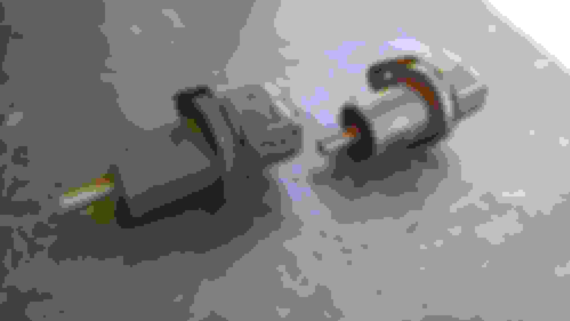
Differential Drain Plug - The drain plug for the MWC 9" is just a shorty bolt. I bought this powerful neodymium magnet to attach to it for the inevitable metallic filings. Note that end magnet and bolt are already pre-scuffed in this pic.
Differential Drain Plug - JB Welded to neodymium magnet
Differential Drain Plug - JB Welded to neodymium magnet
Wheel Speed Sensor Wire Routing
Wheel Speed Sensor Wire Routing
Wheel Speed Sensor Wire Routing
Wheel Speed Sensor Wire Routing
Wheel Speed Sensor Wire Routing
Radiator Leak! - Radiator is an LT1/LS1 combo, so it has the extra fitting at the bottom left. I guess this plug I made wasn't good enough.
Radiator Leak! - Fix it with more band clamps
Rear Brake Lines - I swear I cleaned these already, but man are they rusty.
Rear Brake Lines - All cleaned up
Rear Brake Lines - All cleaned up
LR Fender Bracket - I added this little aluminum bracket inside the LR fender to better mount the plastic liner.
LR Fender Bracket - I added this little aluminum bracket inside the LR fender to better mount the plastic liner.
LR Fender Bracket - I added this little aluminum bracket inside the LR fender to better mount the plastic liner.
Carbon Fiber QA1 Driveshaft! - I got this beauty custom made. Overkill, I know, but CF has better harmonics than aluminum, smaller diameter and weight (~12.5 lbs.), stronger, and shreds if it breaks instead of turning into a giant spinning metal blade.
Carbon Fiber QA1 Driveshaft! - I got this beauty custom made. Overkill, I know, but CF has better harmonics than aluminum, smaller diameter and weight (~12.5 lbs.), stronger, and shreds if it breaks instead of turning into a giant spinning metal blade.
Carbon Fiber QA1 Driveshaft! - I got this beauty custom made. Overkill, I know, but CF has better harmonics than aluminum, smaller diameter and weight (~12.5 lbs.), stronger, and shreds if it breaks instead of turning into a giant spinning metal blade.
Carbon Fiber QA1 Driveshaft! - I got this beauty custom made. Overkill, I know, but CF has better harmonics than aluminum, smaller diameter and weight (~12.5 lbs.), stronger, and shreds if it breaks instead of turning into a giant spinning metal blade.
Oh no! Driveshaft too long?! - Unfortunately, I ran into some serious problems getting the driveshaft to fit. It turns out the issue was the slip yoke was missing a custom counterbore which D&D had added to their Ford 31 spline yoke which came with my T56 Magnum. However, the driveshaft already included a much better slip yoke, and QA1 mentioned that the equivalent cast piece's weight made balancing difficult-to-impossible, so I did not use it.
Oh no! Driveshaft too long?! - Unfortunately, I ran into some serious problems getting the driveshaft to fit. It turns out the issue was the slip yoke was missing a custom counterbore which D&D had added to their Ford 31 spline yoke which came with my T56 Magnum. However, the driveshaft already included a much better slip yoke, and QA1 mentioned that the equivalent cast piece's weight made balancing difficult-to-impossible, so I did not use it.
Driveshaft Solution - I have to commend both QA1 for standing behind their product back and forth with me a half dozen times via phone and email. And also D&D Performance, who took back the QA1 slip yoke and machined it for me in return for only getting back their own slip yoke and the cost of shipping it to them.
Customized Slip Yoke with Counterbore - Much better
Slip Yoke Removal - While taking apart the U-joint to get off the slip yoke for shipping, I think I pressed the first bearing cap too far in and when I went to pop out the other side in the opposite direction, it went a little crooked, busting the bearing cap, and scoring the slip yoke bore.
Slip Yoke Removal - While taking apart the U-joint to get off the slip yoke for shipping, I think I pressed the first bearing cap too far in and when I went to pop out the other side in the opposite direction, it went a little crooked, busting the bearing cap, and scoring the slip yoke bore.
Slip Yoke Removal - While taking apart the U-joint to get off the slip yoke for shipping, I think I pressed the first bearing cap too far in and when I went to pop out the other side in the opposite direction, it went a little crooked, busting the bearing cap, and scoring the slip yoke bore.
I filed down the lip on the slip yoke and all was good
Exhaust, Muffler - Unfortunately, the only way to get this one big piece back in over the larger axle, was to disconnect the watts link bracket and passenger side rear trailing arm. It was super easy once I did that though.
Exhaust, Muffler - Unfortunately, the only way to get this one big piece back in over the larger axle, was to disconnect the watts link bracket and passenger side rear trailing arm. It was super easy once I did that though.
Exhaust, Muffler - Installed
Exhaust, Muffler - Installed
Exhaust, Cats, Y-Pipe - Forward section of exhaust back in car with O2 sensors connected
Exhaust, Cats, Y-Pipe - Forward section of exhaust back in car with O2 sensors connected
Exhaust, Cats, Y-Pipe - Forward section of exhaust back in car with O2 sensors connected
Exhaust, Cats, Y-Pipe - Forward section of exhaust back in car with O2 sensors connected
Exhaust, Cats, Y-Pipe - Forward section of exhaust back in car with O2 sensors connected
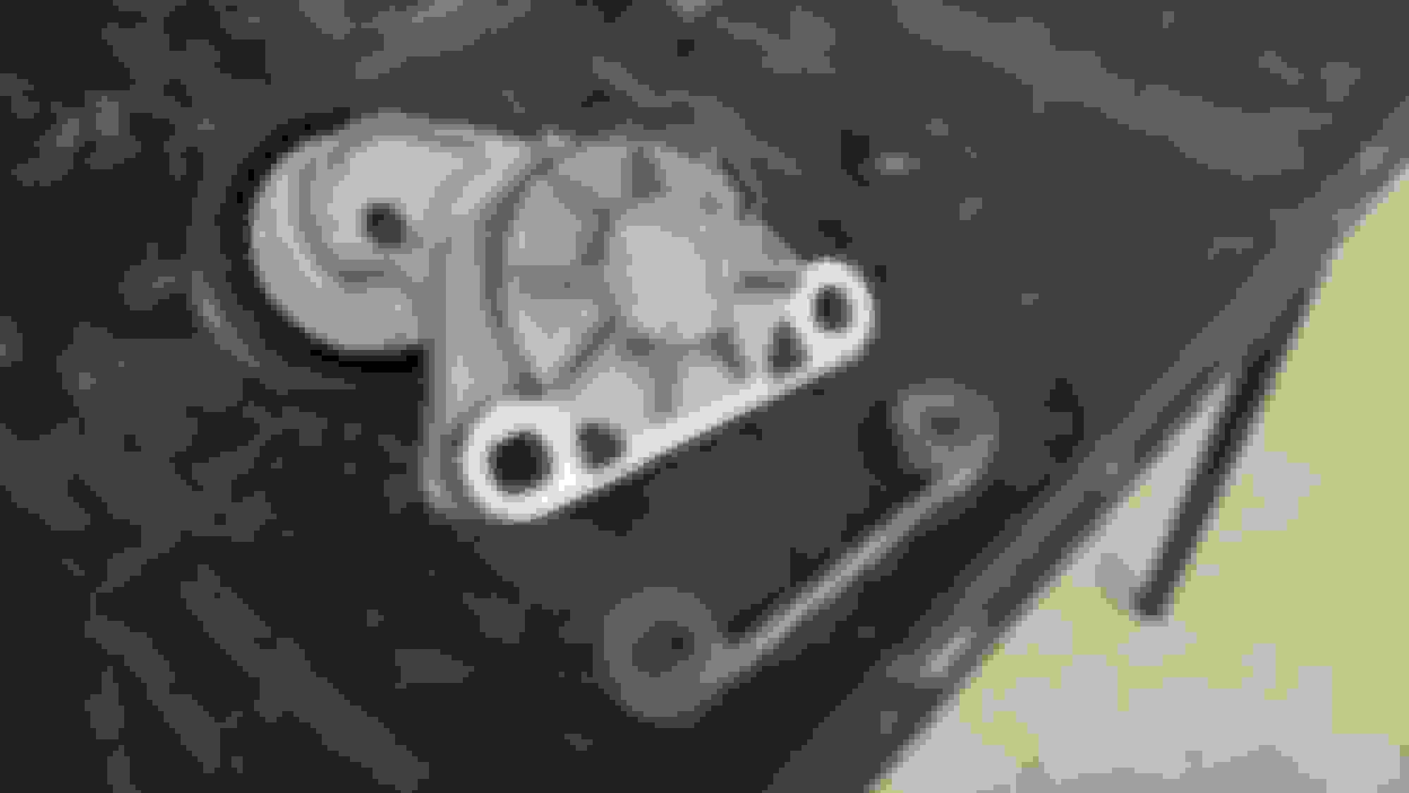
Exhaust Mounting Bracket Installed - Bracket missing here
Exhaust Mounting Bracket Installed - The manual trans bracket is unique, so I bought a used one. Since there is no longer a torque arm mount on the trans, I substituted shorter bolts.
Exhaust Mounting Bracket Installed - The manual trans bracket is unique, so I bought a used one. Since there is no longer a torque arm mount on the trans, I substituted shorter bolts.
Exhaust Mounting Bracket Installed - The manual trans bracket is unique, so I bought a used one. Since there is no longer a torque arm mount on the trans, I substituted shorter bolts.
Exhaust Mounting Bracket Installed - The manual trans bracket is unique, so I bought a used one. Since there is no longer a torque arm mount on the trans, I substituted shorter bolts.
Chassis Brace - A little bending to clear the torque arm
Chassis Brace - A little bending to clear the torque arm
Chassis Brace - A little bending to clear the torque arm
Rear Brake Lines to Axle - Braided metal brake lines connected from chassis to rear axle and bled brakes. I will probably have to go to a brake specialist to cycle the ABS block, as there is definitely air in there. Brake pedal is firm, but you can hear the air inside the ABS solenoids.
Rear Brake Lines to Axle - Braided metal brake lines connected from chassis to rear axle and bled brakes. I will probably have to go to a brake specialist to cycle the ABS block, as there is definitely air in there. Brake pedal is firm, but you can hear the air inside the ABS solenoids.
Rear Anti-Roll Bar Installed - My custom urethane end bushings. Strano's were too soft.
Rear Anti-Roll Bar Installed - My custom urethane end bushings. Strano's were too soft.
Rear Anti-Roll Bar Installed - My custom urethane end bushings. Strano's were too soft.
Rear Springs Installed, Shocks Connected
Adding Gas - This is why you use a filter when pouring gas from a jerry can. This junk was probably still in there from when I drained the tank before. No way to clean out the inside of the jerry can, so who knows what's inside.
Adding Gas - This is why you use a filter when pouring gas from a jerry can. This junk was probably still in there from when I drained the tank before. No way to clean out the inside of the jerry can, so who knows what's inside.
Flushing Fuel Line - Battery installed. New '99-'02 fuel tank and pump with Racetronics pump and hotwire kit work when energizing fuel pump. Flushing fuel lines to remove any errant debris. Looks clean.
Fuel Lines Connected
Replacing Broken Dash Vent - Someone attempted to adjust this by sticking their finger inside and broke the middle slat. Luckily I was able to order an OEM replacement.
Replacing Broken Dash Vent - Someone attempted to adjust this by sticking their finger inside and broke the middle slat. Luckily I was able to order an OEM replacement.
Replacing Broken Dash Vent - Someone attempted to adjust this by sticking their finger inside and broke the middle slat. Luckily I was able to order an OEM replacement.
Replacing Broken Dash Vent - Someone attempted to adjust this by sticking their finger inside and broke the middle slat. Luckily I was able to order an OEM replacement.
Replacing Broken Dash Vent - Someone attempted to adjust this by sticking their finger inside and broke the middle slat. Luckily I was able to order an OEM replacement.
Oil Pre-Luber - I fashioned this from a garden sprayer and some off-the-shelf fittings. Has a shutoff valve to build pressure, and actually a gas fitting was correct for attaching to the block.
Oil Pre-Luber - I fashioned this from a garden sprayer and some off-the-shelf fittings. Has a shutoff valve to build pressure, and actually a gas fitting was correct for attaching to the block.
Oil Pre-Luber - I fashioned this from a garden sprayer and some off-the-shelf fittings. Has a shutoff valve to build pressure, and actually a gas fitting was correct for attaching to the block.
The final mileage before I pulled the LS1, and the baseline mileage for the new LS3.
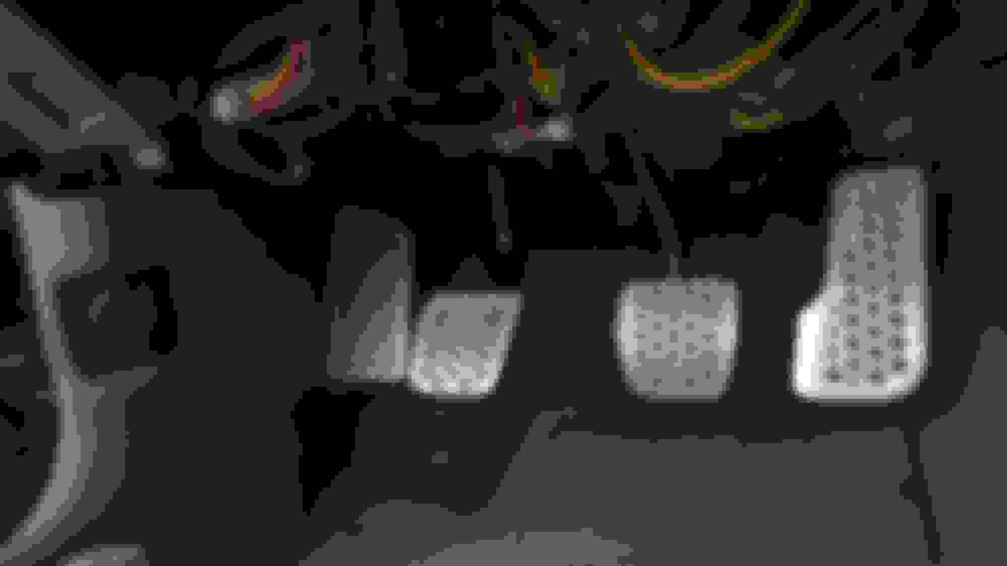
Here are some pics of the pedals I put in last July. I somehow seem to have skipped over them.
New Pedals - The pedals I pulled from the junk yard were pretty worn
New Pedals - Old covers off, adding mounting holes
New Pedals - Old covers off, adding mounting holes
New Pedals - Remove trim for dead-pedal
New Pedals - Remove trim for dead-pedal
New Pedals - Remove trim for dead-pedal
New Pedals - Installing a new set of SRP Racing pedals.
New Pedals - Installing a new set of SRP Racing pedals.
New Pedals - Installing a new set of SRP Racing pedals.
It is currently raining all weekend in LA, so no work this week. However, the next clear weekend day I have, if everything cooperates, the engine will be run for the first time and I will begin the break-in cycle. I still have to take care of registration and insurance, but the car is ready.
So we finally got a break in the weather this weekend, and it was time. Let's start with the introduction (skip this if you know the details already, or you just want to see startup vids):
The first setback was a dead pump in my garden sprayer-turned-preluber. Luckily they are cheap, and I bought another for around $10. I got everything ready, and here's how the first attempt at starting went:
When I got a look underhood, I realized that the serpentine belt was coming off. The reason, is that the Meziere electric water pump is for an LS3--but not an F-Body. The tensioner pulley was sitting too far forward by 7/16", even without using the optional billet spacer. I put a straight edge across the power steering pulley and marked a point on the water pump idler pulley, then spun that over to the tensioner side and marked another point with a straight edge along the tensioner. Then I measured the gap to come up with the 7/16" discrepancy. I realized I could simply machine down the idler pulley to remove the extra 7/16", which is precisely what I did:
Idler Pulley - Removing 7/16"
Idler Pulley - Matched to serpentine belt depth
Idler Pulley - Matched to serpentine belt depth
Cam Position Sensor Extension Harness - A rather prophetic post from over a year ago. Don't do this. Crossing the wires is NOT correct.
So I realized that perhaps crossing the wires on the cam position sensor harness might not be correct, and flipped them back. With the tensioner pulley fixed, and the wiring corrected, here is the long awaited first start:
So it's a bit hard-starting without a base tune on it, and it won't idle below 1000, but that is okay for now. I drove it about 25 feet, but now the trans won't go into gear. It is definitely a clutch issue. I am hoping that there is just an air bubble somewhere in the line, or somewhere in my custom 4' long remote bleeder hose. I spent about an hour bleeding it. After which, I managed to reverse it back the 25' up the driveway, but again it has the same issue. I will make one last attempt at bleeding it this weekend. I can also try it without the remote bleeder. If that fails, that means the slave cylinder needs to be shimmed, and what McLeod support told me over the phone is not correct. I then have to decide if I want to pull the trans myself in the driveway and attempt that, or if I just flatbed tow it to the engine tuner and have him take care of that and the base tune at the same time. He is almost 40 miles away though, so I expect it will run at least $200 for the tow.
Gas Monkey Built a 6-Wheel Ferrari Testarossa With a Corvette LT4 Engine
Slideshow: The controversial Ferrari F6 swaps its original flat-12 for a Corvette Z06-derived LT4 V8 and sends power to four rear wheels through a custom-built drivetrain.
7 Most Reliable High-Performance Engines GM Has Ever Built
Slideshow:These GM engines didn't just make huge power, they survived abuse, boost, track days, and six-digit mileage with a reputation for refusing to quit.
6 Common C5 Corvette Failures and What's Involved In Repairing Them
Slideshow: From wobbling harmonic balancers to failed EBCMs, these are the issues that define long-term C5 ownership and what repairs typically involve.
Retro Modern Bandit Pontiac Trans AM Comes With Burt Reynolds' Autograph
Slideshow: A modern Camaro transformed into a retro icon, this limited-run "Bandit" build blends nostalgia with brute force in a way few revivals manage.
Top 10 Greatest Cadillac V Series Performance Models Ever, Ranked
Slideshow: Cadillac didn't just crash the high-performance luxury vehicle party, it showed up loud, supercharged, and occasionally a little unhinged...
Coachbuilt N2A Anteros Is an LS2-Powered C6 Corvette In Italian Clothes
Slideshow: A one-off sports car that looks like a vintage Italian exotic-but hides a C6 Corvette underneath-just sold for the price of a new mid-engine Corvette.