


Performance LS4 in Fiero NO POWER?

Thread Starter
Teching In
Joined: May 2013
Posts: 10
Likes: 0
I have just finished another swap. The engine is a rebuilt 07 Monte Carlo with a ZO6 cam, DOD delete,GM performance lifters and springs, LS6 intake, Doug Thorley Headers. The car runs (sort of) in just driving in the area it runs like it only has 4 cylinders. I have checked the injectors and am seeing a TPS of 24% on idle. When I drove the car to get it aligned it run as described after I picked it up it ran like it had a rocket in the back. However after having to remove the engine to fix a wiring issue it is back to the no power mode. Another thing is the engine does not respond to the throttle pedal at all in neutral. Anyone have any ideas on what could cause it to run like it is in a limp mode?
All ideas gratefully received
Joe Sokol
All ideas gratefully received
Joe Sokol
Gotta be wiring related - random grounds are like Gremlins !! I'd continuity test your harness with a test light so there's a load, you'll know real quick if a wire isn't right. Far as nuetral issue, do you have a P/N switch wired in?
Swap Gremlins are PITA! I chased a 4.9 swap running rich for months till I found the power steering pressure switch wire was cut... The up side it that it should be something simple.. Hopefully !!
Swap Gremlins are PITA! I chased a 4.9 swap running rich for months till I found the power steering pressure switch wire was cut... The up side it that it should be something simple.. Hopefully !!
Even if he did remove all the DoD stuff it'll still go into V4 mode if he didn't tune it out. He'll be running on 4 cylinders and thus why he has no power. I'm guessing DoD wasn't tuned out as well.
It won't physically hit v4 mode without the dod vlom being in place. I'd assume you have the oil towers blocked off with the regular style valley cover. If anything you should scan the vehicle as this happens so we can get a better picture of what's happening.
TECH Enthusiast
Joined: Nov 2008
Posts: 622
Likes: 1
It won't physically hit v4 mode without the dod vlom being in place.
what has happened here is the 4 fuel injectors for DOD/AFM have been turned off by the ECM, it is not the lifters that are causing the problem. The VLOM has solinoids that are naturally closed, the problem you are encountering has to do with the connector for the VLOM.
The connector has 5 pins A,B,C,D are for each solenoid ECM controlled ground. Pin E is ignition voltage (PK/BK wire color)
The only foolproof way I know is to turn the DOD off completely in the ECM
and a quote from NPM0098 "
Like Ill Born SS said, The connector to the DOD solenoids has +12V and then low side control connections for each solenoid. That +12 is supplied to each solenoid, and the ECU can then pull the low side to ground (using what's called a low side driver (LSD), it sinks current).
I'll try not to get too engineer on you. The solenoids have inductive coils in them which have a significant resistance. By using the LSD to just blip the solenoid, you can check the resistance without actuating it. It's a fairly easy diagnostic to implement, and because it would effect emissions if something went wrong it is a diagnostic that has to be run by law.
So why assume DOD is active? Well, if you didn't and there was a short in the wire that was grounding (thus turning on) one of the DOD lifters (on meaning no lift), then fuel would be injected onto a closed valve every two rotations. After a little bit, you'd have a decent puddle of gas in there that could do all sorts of nasty things. So, the safe bet is to turn off all the DOD injectors if you don't know what state those solenoids are in.
I'd assume you have the oil towers blocked off with the regular style valley cover. If anything you should scan the vehicle as this happens so we can get a better picture of what's happening.
Also to add here this is not the only condition to cause this to happen. Example: The ECT talks to the ECM and if it detects a engine metal overtemp of 128c/262*f it will also shut down 4 injectors to attempt to cool the engine. So if the DOD was in fact tuned out and this is still happening then look here next for a proper functioning ECT system ( a disconnect is the same as overtemp conditions... fails to max hot)
Last edited by Ill_Born_ss; Jan 21, 2014 at 08:48 AM.
Trending Topics
Thread Starter
Teching In
Joined: May 2013
Posts: 10
Likes: 0
Thanks for the replies. The DOD is completely removed including the DOD connector, I looked at a short data log I have and it reports the ECT at 178 climbing to 189 during the log. However the cooling fan comes on after a 4 second delay on engine start. So this might be a start point. I'll do a moving data log and see what that shows.
Again thanks
Joe sokol
Again thanks
Joe sokol
LS1 Tech Stories
The Best V8 Stories One Small Block at Time

6 Common C5 Corvette Failures and What's Involved In Repairing Them
Pouria Savadkouei
Retro Modern Bandit Pontiac Trans AM Comes With Burt Reynolds' Autograph
Verdad Gallardo
Top 10 Greatest Cadillac V Series Performance Models Ever, Ranked
Pouria Savadkouei
Top 10 Most Powerful Chevy Trucks Ever Made!

Hennessey's New Supercharged Silverado ZR2 Has 700 HP
Verdad Gallardo
Coachbuilt N2A Anteros Is an LS2-Powered C6 Corvette In Italian Clothes
Verdad Gallardo
Awesome K5 Blazer Restomod Comes With C7 Corvette Power
Verdad Gallardo
10 Camaros You Should Never Buy

10 LS Engine Myths That Refuse to Die
Verdad GallardoTECH Enthusiast
Joined: Nov 2008
Posts: 622
Likes: 1
That is not correct for the cooling fans, they should only come on low at a given temp and the high fans much later for example.
Yes there is a 3 second delay but not from start, temps must be met.
Did you use or remove the BCM because there is 2 diodes used in the fan system at the BCM. If you are not using the BCM and have access to TSB #Reference Number(s): 09-06-03-007, Date of Issue: August 27, 2009 It will explain and show where to put the diodes in at the fuse box/relay for proper series/parallel - high / low operation.


Does is set any codes? Every time I had my swap run like crap it usually set a code. If not then its likely DoD triggering the Injectors to stop. You might try scanning it while it happens. You can add "V4 time" or "V4 distance" to see when it is commanding DoD.
When tuning my 07 LS4 in a Fiero (no BCM), I had several no-power or dead pedal issues.
At one time the fan started coming on almost immediately and running like crap, ended up being a corrupt tune. I went back to the stock tune, with just the injector size change, started the car and the fan stayed off. Then I copied over the other changes and the fan stayed off.
If the battery is low when the car starts it will run like crap, but normally sets a code. Clear the code, charge the battery and started up and ran great.
A corroded terminal/bad connection at the TB would make it run like crap, set multiple DTC and kill pedal function - happened randomly about 5 times - usually at a gas station for some reason. I cleaned the terminals and use some vice grips to twist the blades of the terminals about 10 degrees (just so they would drag in the connector) and have never had it happens since.
The range switch is the likely culprit for the non-responsive pedal. I caused the issue several times trying to mimick the range switch inputs on my manual swap... never solved it and just wired it up as D4 all the time and had Darth remove the "range switch not in P/N at start" code with Tuner Cat (HP Tuners doesn't have access to the code). I think the ecm expects to see P, then R, then N, then D4. If it sees them out of sequence it goes nuts and the pedal becomes non-responsive. Might check the 4 range switch wires for the proper open/ground sequence in P, R, N, D
I also tripped the no-power mode a few times tuning speed density and forgetting to change the RPM ranges at the top of the coefficient ranges.
Last edited by fieroguru; Jan 21, 2014 at 03:07 PM.
Which timing chain sprocket (cam) did you use when you did the cam change?
Does it start right up quickly or does it take serveral rotations of the engine to start?
Any over heating or running warmer than normal?
Is it the same LS4 PCM that came with engine?
I would check the simple stuff first- all injectors/coils/wires firing, fuel filter/fuel regulator, good fuel, ect. If it was running great then running poorly, and the car had wiring issues it sounds like it could still be in the wiring....
Keep us updated~
Thread Starter
Teching In
Joined: May 2013
Posts: 10
Likes: 0
Did a run today I monitored the ETC Pedal 1 and 2 they have a difference at idle 1 reads 1.02 V and 2 reads 0.49 and stay with 1 being double the voltage of 2. The Throttle position sensor never moved beyond 40% even with a full throttle request. I need to check the wiring to the throttle pedal as I would assume that they should both read the same.
Joe
Joe
Thread Starter
Teching In
Joined: May 2013
Posts: 10
Likes: 0
So I took the original tune from the car and turned off the DOD and unnecessary DTC's. Took the car out and now it has the power it should. I guess I'll have to talk with the guy I got the tune from and see what he has to say. One problem that I still have is the fan turns on after about 4 seconds?
Joe
Joe
TECH Enthusiast
Joined: Nov 2008
Posts: 622
Likes: 1
Good to hear, as for the pedal 1/2 thing if I remember correctly they are supposed to be opposite of each other ( one of them starts at high V and the other starts low V) I would have to check tomorrow for you, kid got the car.
The fans are they coming on low or high speed and what do they do if you pull the sensor connector with the ignition on. ( they are supposed to default to high )
The fans are they coming on low or high speed and what do they do if you pull the sensor connector with the ignition on. ( they are supposed to default to high )
Thread Starter
Teching In
Joined: May 2013
Posts: 10
Likes: 0
I wired the a fan relay to be controlled by the ECM this relay provides a ground to the Fiero fan relay. I guess more wire checking is in order. Never has this much trouble with wiring before. Must be getting OLD
Joe Sokol
Joe Sokol
TECH Enthusiast
Joined: Nov 2008
Posts: 622
Likes: 1
I have to do this in 2 posts as there is 1300 characters to many for a single post.
2007 Chevrolet Monte Carlo 5.3L Eng SS
THROTTLE ACTUATOR CONTROL (TAC) SYSTEM DESCRIPTION
The throttle actuator control (TAC) system delivers improved throttle response and greater reliability and eliminates the need for mechanical cable. The TAC system performs the following functions:
• Accelerator pedal position sensing
• Throttle positioning to meet driver and engine demands
• Throttle position sensing
• Internal diagnostics
• Cruise control functions
• Manage TAC electrical power consumption
The TAC system includes the following components:
• The accelerator pedal position (APP) sensors
• The throttle body assembly
• The engine control module (ECM)
ACCELERATOR PEDAL POSITION (APP) SENSOR
The accelerator pedal contains 2 individual APP sensors within the assembly. The Accelerator Pedal Position (APP) sensors 1 and 2 are potentiometer type sensors each with 3 circuits:
• A 5-volt reference circuit
• A low reference circuit
• A signal circuit
The APP sensors are used to determine the pedal angle. The engine control module (ECM) provides each APP sensor a 5-volt reference circuit and a low reference circuit. The APP sensors provide the ECM with signal voltage proportional to the pedal movement. The APP sensor 1 signal voltage at rest position is less than 1 volt and increases to above 4 volts as the pedal is actuated. The APP sensor 2 signal voltage at rest position is near 0.5 volt and increases to more than 2 volts as the pedal is actuated.
THROTTLE BODY ASSEMBLY
The throttle assembly contains the following components:
• The throttle blade
• The throttle actuator motor
• The throttle position (TP) sensor 1 and 2
The throttle body functions similar to a conventional throttle body with the following exceptions:
• An electric motor opens and closes the throttle valve.
• The throttle blade is spring loaded in both directions and the default position is slightly open.
• There are 2 individual TP sensors within the throttle body assembly.
The TP sensors are used to determine the throttle plate angle. The TP sensors provide the engine control module (ECM) with a signal voltage proportional to throttle plate movement. The TP sensor 1 signal voltage at closed throttle is above 4 volts and decreases as the throttle plate is opened. The TP sensor 2 signal voltage at closed throttle is below 1 volt and increases as the throttle plate is opened.
ENGINE CONTROL MODULE
The engine control module (ECM) is the control center for the throttle actuator control (TAC) system. The ECM determines the drivers intent and then calculates the appropriate throttle response. The ECM achieves throttle positioning by providing a pulse width modulated voltage to the TAC motor.
MODES OF OPERATION > NORMAL MODE
During the operation of the throttle actuator control (TAC) system, several modes or functions are considered normal. The following modes may be entered during normal operation:
• Minimum pedal value-At key-up the engine control module (ECM) updates the learned minimum pedal value.
• Minimum throttle position (TP) values-At key-up the ECM updates the learned minimum TP value. In order to learn the minimum TP value, the throttle blade is moved to the closed position.
• Ice break mode-If the throttle is not able to reach a predetermined minimum throttle position, the ice break mode is entered. During the ice break mode, the ECM commands the maximum pulse width several times to the throttle actuator motor in the closing direction.
• Battery saver mode-After a predetermined time without engine RPM, the ECM commands the battery saver mode. During the battery saver mode, the TAC module removes the voltage from the motor control circuits, which removes the current draw used to maintain the idle position and allows the throttle to return to the spring loaded default position.
MODES OF OPERATION > REDUCED ENGINE POWER MODE
When the ECM detects a condition with the TAC system, the ECM may enter a reduced engine power mode. Reduced engine power may cause one or more of the following conditions:
• Acceleration limiting-The ECM will continue to use the accelerator pedal for throttle control; however, the vehicle acceleration is limited.
• Limited throttle mode-The ECM will continue to use the accelerator pedal for throttle control; however, the maximum throttle opening is limited.
• Throttle default mode-The ECM will turn off the throttle actuator motor and the throttle will return to the spring loaded default position.
• Forced idle mode-The ECM will perform the following actions:
o Limit engine speed to idle by positioning the throttle position, or by controlling the fuel and spark if the throttle is turned off.
o Ignore the accelerator pedal input.
• Engine shutdown mode-The ECM will disable fuel and de-energize the throttle actuator.
ACCELERATOR PEDAL POSITION (APP) SENSOR
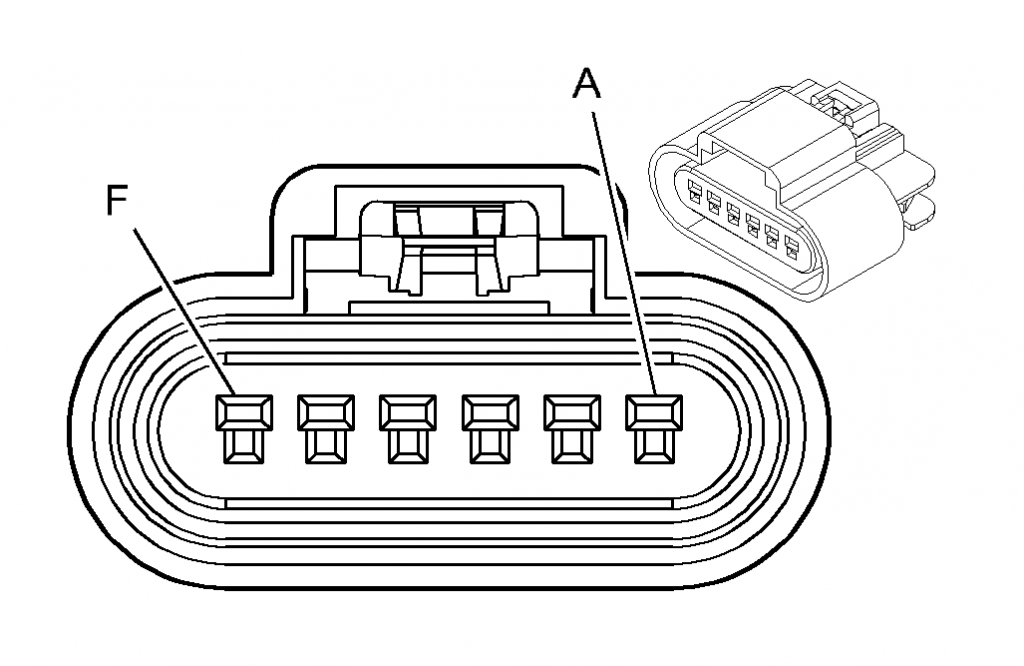
Fig 1: Accelerator Pedal Position (APP) Sensor Connector End View
Accelerator Pedal Position (APP) Sensor Connector Parts Information
Connector Part Information
• OEM: 15326829
• Service: 88953153
• Description: 6-Way F Metri-Pack 150 Series, Sealed (BK)
Terminal Part Information
• Terminal/Tray: 12191819/8
• Core/Insulation Crimp: E/A
• Release Tool/Test Probe: 15315247/J-35616-2A (GY)
Accelerator Pedal Position (APP) Sensor Connector Terminal Identification
Pin Wire Color Circuit No. Function
A PU 1272 Low Reference
B L-BU 1162 APP Sensor 2 Signal
C TN 1274 5-Volt Reference 2
D BN 1271 5-Volt Reference 1
E D-BU 1161 APP Sensor 1 Signal
F WH/BK 1164 Low Reference
Last edited by Ill_Born_ss; Jan 23, 2014 at 06:02 AM.
TECH Enthusiast
Joined: Nov 2008
Posts: 622
Likes: 1
THROTTLE BODY
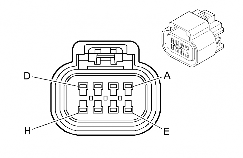
Fig 1: Throttle Body Connector End View Courtesy of GENERAL MOTORS CORP.
Throttle Body Connector Parts Information
Connector Part Information
• OEM: 15326836
• Service: 88986255
• Description: 8-Way F GT 150 Series, Sealed (BK)
Terminal Part Information
• Terminal/Tray: 12191819/8
• Core/Insulation Crimp: E/A
• Release Tool/Test Probe: 15315247/J-35616-2A (GY)
Throttle Body Connector Terminal Identification
Pin Wire Color Circuit No. Function
A D-GN 485 TP Sensor 1 Signal
B L-BU 6295 5-Volt Reference 2
C TN 2752 Low Reference
D PU 486 TP Sensor 2 Signal
E YE 581 TAC Motor Control - 1
F BN 582 TAC Motor Control - 2
G GY 2701 5-Volt Reference 2
H L-BU/BK 6297 Low Reference
THROTTLE ACTUATOR CONTROL (TAC) SYSTEM
The throttle actuator control (TAC) system delivers improved throttle response and greater reliability and eliminates the need for mechanical cable. The TAC system performs the following functions:
• Accelerator pedal position sensing
• Throttle positioning to meet driver and engine demands
• Throttle position sensing
• Internal diagnostics
• Cruise control functions
• Manage TAC electrical power consumption
The TAC system includes the following components:
• The accelerator pedal position (APP) sensors
• The throttle body assembly
• The engine control module (ECM)
ACCELERATOR PEDAL POSITION (APP) SENSOR
The accelerator pedal contains 2 individual APP sensors within the assembly. The Accelerator Pedal Position (APP) sensors 1 and 2 are potentiometer type sensors each with 3 circuits:
• A 5-volt reference circuit
• A low reference circuit
• A signal circuit
The APP sensors are used to determine the pedal angle. The engine control module (ECM) provides each APP sensor a 5-volt reference circuit and a low reference circuit. The APP sensors provide the ECM with signal voltage proportional to the pedal movement. The APP sensor 1 signal voltage at rest position is less than 1 volt and increases to above 4 volts as the pedal is actuated. The APP sensor 2 signal voltage at rest position is near 0.5 volt and increases to more than 2 volts as the pedal is actuated.
THROTTLE BODY ASSEMBLY
The throttle assembly contains the following components:
• The throttle blade
• The throttle actuator motor
• The throttle position (TP) sensor 1 and 2
The throttle body functions similar to a conventional throttle body with the following exceptions:
• An electric motor opens and closes the throttle valve.
• The throttle blade is spring loaded in both directions and the default position is slightly open.
• There are 2 individual TP sensors within the throttle body assembly.
The TP sensors are used to determine the throttle plate angle. The TP sensors provide the engine control module (ECM) with a signal voltage proportional to throttle plate movement. The TP sensor 1 signal voltage at closed throttle is above 4 volts and decreases as the throttle plate is opened. The TP sensor 2 signal voltage at closed throttle is below 1 volt and increases as the throttle plate is opened.
ENGINE CONTROL MODULE
The engine control module (ECM) is the control center for the throttle actuator control (TAC) system. The ECM determines the drivers intent and then calculates the appropriate throttle response. The ECM achieves throttle positioning by providing a pulse width modulated voltage to the TAC motor.
MODES OF OPERATION > NORMAL MODE
During the operation of the throttle actuator control (TAC) system, several modes or functions are considered normal. The following modes may be entered during normal operation:
• Minimum pedal value-At key-up the engine control module (ECM) updates the learned minimum pedal value.
• Minimum throttle position (TP) values-At key-up the ECM updates the learned minimum TP value. In order to learn the minimum TP value, the throttle blade is moved to the closed position.
• Ice break mode-If the throttle is not able to reach a predetermined minimum throttle position, the ice break mode is entered. During the ice break mode, the ECM commands the maximum pulse width several times to the throttle actuator motor in the closing direction.
• Battery saver mode-After a predetermined time without engine RPM, the ECM commands the battery saver mode. During the battery saver mode, the TAC module removes the voltage from the motor control circuits, which removes the current draw used to maintain the idle position and allows the throttle to return to the spring loaded default position.
MODES OF OPERATION > REDUCED ENGINE POWER MODE
When the ECM detects a condition with the TAC system, the ECM may enter a reduced engine power mode. Reduced engine power may cause one or more of the following conditions:
• Acceleration limiting-The ECM will continue to use the accelerator pedal for throttle control; however, the vehicle acceleration is limited.
• Limited throttle mode-The ECM will continue to use the accelerator pedal for throttle control; however, the maximum throttle opening is limited.
• Throttle default mode-The ECM will turn off the throttle actuator motor and the throttle will return to the spring loaded default position.
• Forced idle mode-The ECM will perform the following actions:
o Limit engine speed to idle by positioning the throttle position, or by controlling the fuel and spark if the throttle is turned off.
o Ignore the accelerator pedal input.
• Engine shutdown mode-The ECM will disable fuel and de-energize the throttle actuator.
As for your fans I need more info on what you done.
I'm wondering if its cause ls4 fans are pwm and your fiero fans jiswork on a conventional on/off type system
Then in the Fan% vs. ECT table, set everything to 90 except the first cell (192 degrees). If you fill it in, once the fan goes on it won't shut back off till the ignition is turned off.
Thread Starter
Teching In
Joined: May 2013
Posts: 10
Likes: 0
The problem I had with no power turned out to be a corrupted tune. I install ed the original turn and the car ran great. I got a new tune sent to me from LSX Power Tuning and installed and now the car runs great.
Put it on the dyno got 280 hp and 267 ft pounds of torque to the ground on an complete rebuild with 160 miles on it.
Thanks again for all the help.
Joe Sokol (Fieroking)
Put it on the dyno got 280 hp and 267 ft pounds of torque to the ground on an complete rebuild with 160 miles on it.
Thanks again for all the help.
Joe Sokol (Fieroking)