Biology of an Optispark..........

Thread Starter
Teching In
Joined: Oct 2008
Posts: 33
Likes: 1
From: Central PA
Well my Impala is not running and I am frustrated getting now where on it. My new to me MSD opti is on its way (hopefully this is my problem), so I decided to re-install a used MSD cap on an Opti and replace the bearing with a better one. Pictures included. I hope this takes some of the mystery out of the Opti.... I know it did for me.
First I disassembled the opti. The right tools helps. I got mine at Car Quest for about $6:
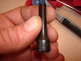
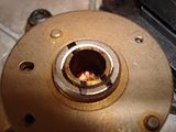
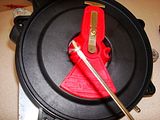
Remove the cap with the 4 E4 screws. It will then easily come apart. Two screws hold the rotor down. These are small torx. This should be fairly straight forward. remove the inner cover. This will be white or black plastic. Remove the thin metal dust cover. Now you are looking at the optical sensor and the wheel that triggers it:
***This is as far as you need to disassemble the Opti to replace the cap and rotor***
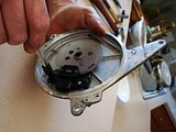
The sensor will come out fairly easily by removing the two female Torx screws. Then you can remove the trigger plate and the spacer below:


I marked the shaft to it would be in time when I reassembled it:
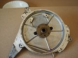
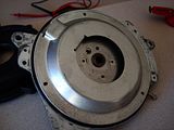
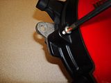
I then used a punch and put the opti chassis loosely on my vice. I used a drift to drive the input shaft down out of the bearing. The bearing comes out easily on the inside with the two torx screw. This is fully disassembled:

I then used a bearing out of a tighter opti:

Simply reverse the process. Be sure to start all screws by hand when you install, I used blue threadlock on each screw:

Drive the shaft back into the bearing from the back. The inner hub will sit flush on a flat surface so if you drive the shaft in gently you should not be able to drive it to far in. It was flush prior to *** assembly. Use a piece of brass or wood to drive it so you do not deform the shaft. Do not do this on your kitchen counter. This was for the picture only:

Be sure your timing marks line up!! This is critical if you want the Opti to work .
.
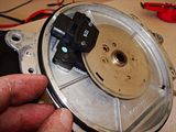
I cleaned the sensor surfaces with 99% pure alcohol use for fiber optics in the communications industry. I blew it off with canned air. I also cleaned the trigger wheel and spacer the same way. I then put the spacer and trigger back in place (they can only go one way):

And slowly reinstalled the sensor going back and forth between screws to be sure not to **** it sideways. There are two pins that hold this in place it is a nice firm attachment:
I tested my sensor for grins. Not sure what I am supposed to see, but the two pins the the left had 5.07 m Ohms between them. None of the others showed any conductivity. I tested another sensor and got 4.75 so I assumed this was good:

NEXT POST
First I disassembled the opti. The right tools helps. I got mine at Car Quest for about $6:

Remove the cap with the 4 E4 screws. It will then easily come apart. Two screws hold the rotor down. These are small torx. This should be fairly straight forward. remove the inner cover. This will be white or black plastic. Remove the thin metal dust cover. Now you are looking at the optical sensor and the wheel that triggers it:

***This is as far as you need to disassemble the Opti to replace the cap and rotor***
The sensor will come out fairly easily by removing the two female Torx screws. Then you can remove the trigger plate and the spacer below:


I marked the shaft to it would be in time when I reassembled it:

I then used a punch and put the opti chassis loosely on my vice. I used a drift to drive the input shaft down out of the bearing. The bearing comes out easily on the inside with the two torx screw. This is fully disassembled:

I then used a bearing out of a tighter opti:

Simply reverse the process. Be sure to start all screws by hand when you install, I used blue threadlock on each screw:

Drive the shaft back into the bearing from the back. The inner hub will sit flush on a flat surface so if you drive the shaft in gently you should not be able to drive it to far in. It was flush prior to *** assembly. Use a piece of brass or wood to drive it so you do not deform the shaft. Do not do this on your kitchen counter. This was for the picture only:

Be sure your timing marks line up!! This is critical if you want the Opti to work
.I cleaned the sensor surfaces with 99% pure alcohol use for fiber optics in the communications industry. I blew it off with canned air. I also cleaned the trigger wheel and spacer the same way. I then put the spacer and trigger back in place (they can only go one way):

And slowly reinstalled the sensor going back and forth between screws to be sure not to **** it sideways. There are two pins that hold this in place it is a nice firm attachment:
I tested my sensor for grins. Not sure what I am supposed to see, but the two pins the the left had 5.07 m Ohms between them. None of the others showed any conductivity. I tested another sensor and got 4.75 so I assumed this was good:

NEXT POST
Thread Starter
Teching In
Joined: Oct 2008
Posts: 33
Likes: 1
From: Central PA
Now dust cover:
Next I cleaned up the large seal between the chassis and the inner cap. I used a little dielectric silicone to keep it supple and clean it up:
Inner cap:
Rotor with threadlock on screws. The MSD rotor was harder to put the screws into, so I turned it upside down and putt the screws in from below:
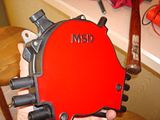
Cap with screws from MSD (these are phillips head not Torx):
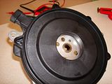
And she is done:


Next I cleaned up the large seal between the chassis and the inner cap. I used a little dielectric silicone to keep it supple and clean it up:

Inner cap:

Rotor with threadlock on screws. The MSD rotor was harder to put the screws into, so I turned it upside down and putt the screws in from below:

Cap with screws from MSD (these are phillips head not Torx):

And she is done:


TECH Senior Member
iTrader: (3)
Joined: Oct 2006
Posts: 7,564
Likes: 4
From: Decatur, TN (N-W of Athens)
Drive the shaft back into the bearing from the back. The inner hub will sit flush on a flat surface so if you drive the shaft in gently you should not be able to drive it to far in, I suggest the counter top of your nice kitchen for this.

Nice write up, hope it works, if that was the intent. Unless you're like me and just like to tear **** apart lol
Thread Starter
Teching In
Joined: Oct 2008
Posts: 33
Likes: 1
From: Central PA
I seriously doubt your marker line will allow you to realign such small parts close enough to be within a few degrees and this is a thing where 2-3 degrees is HUGE.
Probably a bad time to tell you the MSD opti is a step BACKWARDS from stock too, many of the guys who tried them are selling them off after MSD repairs them.
Nice pictures of disassembling the opti though, thanks for sharing I am certain the will be of help to someone.
Probably a bad time to tell you the MSD opti is a step BACKWARDS from stock too, many of the guys who tried them are selling them off after MSD repairs them.
Nice pictures of disassembling the opti though, thanks for sharing I am certain the will be of help to someone.
Thread Starter
Teching In
Joined: Oct 2008
Posts: 33
Likes: 1
From: Central PA
Yah..... I am a little concerned on the timing thing myself, but I really don't plan on using the who Opti. Most likely just the cap and rotor. I put it on to see if my engine will fire anyway........
Trending Topics
This is the problem here, constructive criticism is NOT bashing. Only way I would trust a marker width mark to line up something that critical is if it were on a 2foot diameter circle.
The MSD cap and rotor seem pretty good but the billet ase that is supposed to be so wonderful has cause a lot of troubles, from bad bearings, excessive thrust, bad optical sensors etc. Far more troublesome than the stocker everyone loves to bash.
LS1 Tech Stories
The Best V8 Stories One Small Block at Time

Top 10 Greatest Cadillac V Series Performance Models Ever, Ranked
Pouria Savadkouei
Top 10 Most Powerful Chevy Trucks Ever Made!

Hennessey's New Supercharged Silverado ZR2 Has 700 HP
Verdad Gallardo
Coachbuilt N2A Anteros Is an LS2-Powered C6 Corvette In Italian Clothes
Verdad Gallardo
Awesome K5 Blazer Restomod Comes With C7 Corvette Power
Verdad Gallardo
10 Camaros You Should Never Buy

10 LS Engine Myths That Refuse to Die
Verdad Gallardo
Five Reasons the Camaro Was the Most Pivotal Player in the Pony Car Wars 2.0
Brett Foote