


Valve geometry correct? (pic)
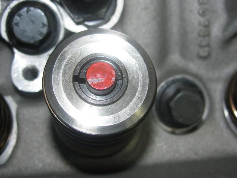
This is cylinder #1 intake valve and the mark is leaning toward the exhaust valve. I remember reading that as long as it's toward the exhaust it's ok. Correct? (Note that this is with the test pushrod @ 7.2", I never took pics of the correct rod length and they all made this mark.) Thanx
This is cylinder #1 intake valve and the mark is leaning toward the exhaust valve. I remember reading that as long as it's toward the exhaust it's ok. Correct? (Note that this is with the test pushrod @ 7.2", I never took pics of the correct rod length and they all made this mark.) Thanx
It looks decent. I will speculate that if you put in a 7.150" PR, the pattern will move to the center but the sweep will get larger. More sweep means more parasitic power loss and IMO has more negative impact than the patter being a tad off center as shown in the pic. You definitely dont want the pattern going much further to the exhaust side than what is in the pic. BTW it is near impossible to have very minimal sweep and the perfect centered pattern so avoid looking for that treasure.
It looks decent. I will speculate that if you put in a 7.150" PR, the pattern will move to the center but the sweep will get larger. More sweep means more parasitic power loss and IMO has more negative impact than the patter being a tad off center as shown in the pic. You definitely dont want the pattern going much further to the exhaust side than what is in the pic. BTW it is near impossible to have very minimal sweep and the perfect centered pattern so avoid looking for that treasure.

TECH Apprentice

Joined: Mar 2007
Posts: 313
Likes: 5
From: Eastern PA
If you have a pushrod checker tool, then test one with 7.15". Are you using LS7 lifters? They tend to require a slightly shorter pushrod. I ended up with 7.15" pushrods with stock, untouched heads (not that you should go by that, always measure).
Interesting that your PR length is the same as mine. My heads are milled .012" and the head gasket is .026". What gasket and rockers did you use?
Trending Topics
LS1 Tech Stories
The Best V8 Stories One Small Block at Time

Topdon ONE vs. Artidiag 800 BT2: Which is the Diagnostic Tablet For You?
Pouria Savadkouei
Gas Monkey Built a 6-Wheel Ferrari Testarossa With a Corvette LT4 Engine
Verdad Gallardo
7 Most Reliable High-Performance Engines GM Has Ever Built
Verdad Gallardo
Amazing '71 Camaro Restomod Is Modern Muscle Car Under the Skin
Verdad Gallardo
6 Common C5 Corvette Failures and What's Involved In Repairing Them
Pouria Savadkouei
Retro Modern Bandit Pontiac Trans AM Comes With Burt Reynolds' Autograph
Verdad Gallardo
Top 10 Greatest Cadillac V Series Performance Models Ever, Ranked
Pouria Savadkouei
Top 10 Most Powerful Chevy Trucks Ever Made!

Hennessey's New Supercharged Silverado ZR2 Has 700 HP
Verdad GallardoAl 95 Z28 w/ Manley Pro-Flows
TECH Apprentice
Joined: Mar 2007
Posts: 313
Likes: 5
From: Eastern PA
There were pics posted a while ago on cz28.com showing the cup height difference between stock LT1 and LS7 lifters, maybe they changed... that's why I said to measure and be sure.
I measured the two side by side with a dial indicator a while ago. The cup in the LS7 lifter sits about .050" deeper in the lifter body. IMO, they did this to the cup end to provide more metal above the retainer clip to for a bit more strength.
Regardless, this slight difference will do little to affect PR length.
Regardless, this slight difference will do little to affect PR length.
My question is what exactly was the Lifter you had?
I ask cause my LS7's were shallower than a stock LS1 Lifter..and I have a stock set of Lifters here in my garage that came out of an LS1. They arent stock LS1 Lifters..they look identical to LS7 Lifters, but the cup is the same as a LS1 Lifter.
Here is some info I found to help out FWIW..
LS7 on the left, stock on the right.

http://www.camaroz28.com/forums/showthread.php?t=690137
Last edited by the_merv; Aug 31, 2011 at 11:46 PM.

.050" of an inch is a decent amount on the Pushrod geometry..that's a .050" longer Pushrod needed to compensate for it.
My question is what exactly was the Lifter you had?
I ask cause my LS7's were shallower than a stock LS1 Lifter..and I have a stock set of Lifters here in my garage that came out of an LS1. They arent stock LS1 Lifters..they look identical to LS7 Lifters, but the cup is the same as a LS1 Lifter.
Here is some info I found to help out FWIW..
LS7 on the left, stock on the right.
http://www.camaroz28.com/forums/showthread.php?t=690137

Absolutely. This was the problem with the Comp R lifter. The later versions had a paper thin retainer clip. Those with unstable valve trains would toss a lifter, the plunger would then hammer on the clip, the clip would effortlessly break and then you would read about the bitching of the lifter being bad. That clip serves no function while the lifter is in the engine and the valvetrain is properly adjusted.
