$10 DIY LT1 programming data logging USB cable vid
#1
Thread Starter
Joined: Apr 2007
Posts: 1,999
Likes: 105
From: Hog Back, KS
I thought it may get more traffic over here rather than the PCM tuning section as it's LT1 specific.
So I have sold hundreds of these and the demand has dropped off so I decided to show you all how to make your own USB programming cable. These can be built for less than $10 total.
All you need is a USB to serial adapter with a FTDI chip on it and a 1000 ohm resistor and a simple glass diode. The USB to serial adapter can be had on ebay. The resistor and diode can be bought at radio shack for cheap.
The build and testing directions are in the vid but I will repeat them here.
Solder the resistor to the diode end without the black stripe. Solder the other end of the resistor to the RX terminal on the USB adapter. Solder the diode other end with the black stripe to the TX terminal in the USB adapter.
Then connect the adapter ground terminal to your car obd port black wire. Connect the resistor/diode to the tan wire on your obd port. It will work with either square and obd2 style port. Just look at the back of the port for wire colors.
Here is a link to the build and test video using data master data logging software.
Enjoy !
Last edited by aknovaman; 05-12-2014 at 10:23 PM.
#4
Thread Starter
Joined: Apr 2007
Posts: 1,999
Likes: 105
From: Hog Back, KS
http://www.gmassie.net/13secss/benchtop.pdf
Just connect the power as shown here and the benchtop harness ground and data wires to the USB adapter.
I just found a 12 volt wall wart that outs out at least 500 mA. The PCM does not draw much current while just sitting there.
Just connect the power as shown here and the benchtop harness ground and data wires to the USB adapter.
I just found a 12 volt wall wart that outs out at least 500 mA. The PCM does not draw much current while just sitting there.
#6
Is there any reason this cable will not work?
http://www.gearbest.com/development-.../pp_54471.html
You still need the resistor and diode, I'm sure, but this looks like the cheapest way to go
http://www.gearbest.com/development-.../pp_54471.html
You still need the resistor and diode, I'm sure, but this looks like the cheapest way to go
#7
Is there any reason this cable will not work?
http://www.gearbest.com/development-.../pp_54471.html
You still need the resistor and diode, I'm sure, but this looks like the cheapest way to go
http://www.gearbest.com/development-.../pp_54471.html
You still need the resistor and diode, I'm sure, but this looks like the cheapest way to go
A lot of newer electronics are like this, and the only difference for them is the voltages the "serial" operates at.
The old serial (RS-232 IIRC)was designed for about -13 - +13v.
It may work, work wrong, or just burn up.
Trending Topics
#8
With what I said before I think this adapter will work
Part# USB-RS232-WE-1800-BT_0.0 found on http://www.ftdichip.com/Products/Cables/USBRS232.htm
Part# USB-RS232-WE-1800-BT_0.0 found on http://www.ftdichip.com/Products/Cables/USBRS232.htm
#10
I am fairly sure it does.
One time I was trying to make my own cable. I got frustrated I ended up just running the data line into the into the serial port and the computer was able to read the line, but not send anything. This was an old crappy laptop with both a serial and parallel port.
One time I was trying to make my own cable. I got frustrated I ended up just running the data line into the into the serial port and the computer was able to read the line, but not send anything. This was an old crappy laptop with both a serial and parallel port.
#20
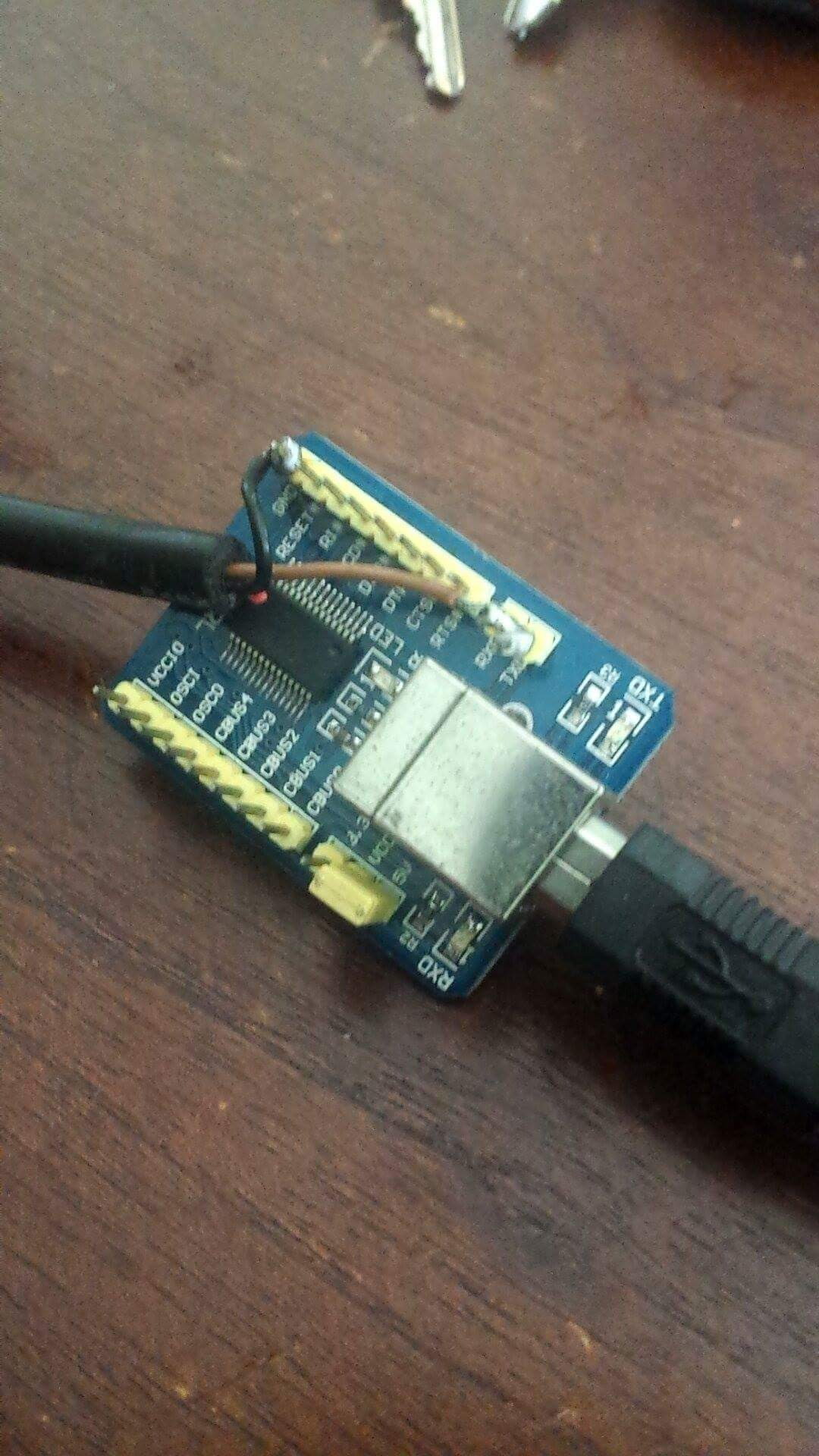
I didn't use a diode or resistor.
i bought one of these:
http://www.ebay.com/itm/FT232RL-USB-...8AAOSwI59aTGDT
and one of these:
http://www.ebay.com/itm/GM-12-Pin-OB...8AAOSwkLhaAvGZ
and I cut the cable and soldered the tx/rx pins together and to the cable.
i soldered the ground pin to the cable.
you will need to verify which wires in the cable are correct using a multimeter or test light.

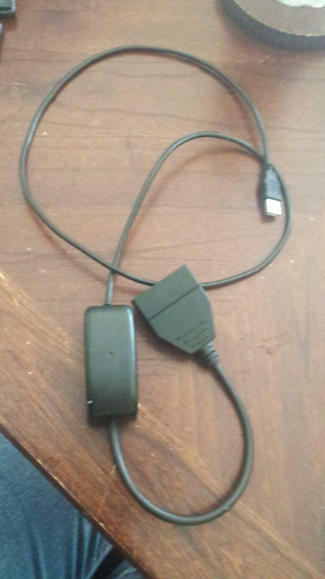
complete cable

been using it to scan and program for years without issue.


