When you click on links to various merchants on this site and make a purchase, this can result in this site earning a commission. Affiliate programs and affiliations include, but are not limited to, the eBay Partner Network.
This is a high level summary. Assuming you have built at least a few t56/tr6060 transmissions.
The truck doesn't get a lot of attention but the first question is always "how?" followed by trying to correct me that something either won't work or isn't strong enough. The next question is usually "why?" Goal was to have traction on the street with a regular street tire. I've built multiple 700+hp rear wheel drive cars. Even with radials traction is always a challenge.
In five years and a few thousand miles I have broken one t56 and zero transfer cases. I just recently built a new trans after wiping the teeth off of 3rd and a counter shaft. If this one lasts as long I will be happy. I have not broken output shafts or wheel studs. I've broken a few stock front S10 diff housings. Poly bushings may have made it worse. Gone back to stock bushings.
Prereqs:
- Complete C5 T56 (you could use others but honestly this is the cheapest option)
- T56 midshift conversion pieces and shifter
- F/GTO/V T56 midplate
- F/GTO/V T56 Bellhousing
- Waterjet/lathe/tig (see below)
- BW4472 (or whatever 27 spline transfer case you want to run - other options viable if you have ability to make custom transmission output shaft or input shaft for transfer case)
The transmission to transfer case adapter:
This is the most complicated part of the build. I wanted a bolt together solution where parts could be replaced if needed. I also kept the GM 700R/4l60 transfer case adapter. It gave some additional length. You could eliminate and make your adapter longer.
My choice of a 27 spline output shaft and transfer case with the same input means the two will slide together with no mods. This is why I started with a C5 transmission. The output shaft is long enough. We just need to connect the housings. C5 trans slid into BW4472 transfer case.
Now you either need access to a waterjet, or at least the ability to model both flanges and find an online service to cut your flanges.
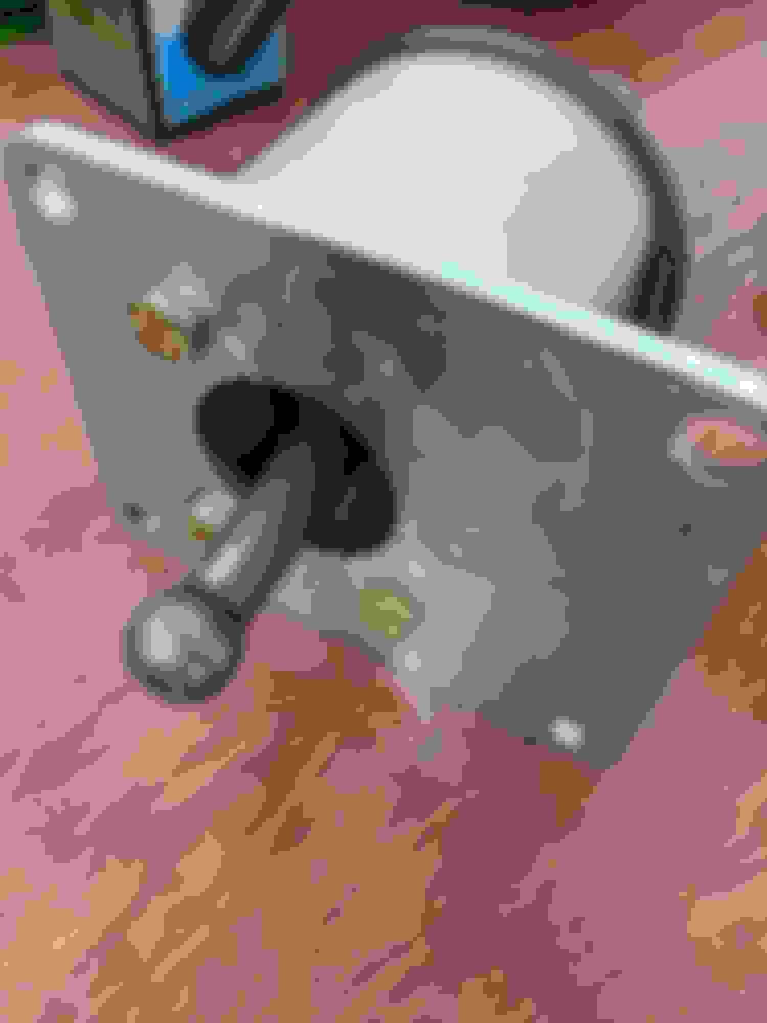
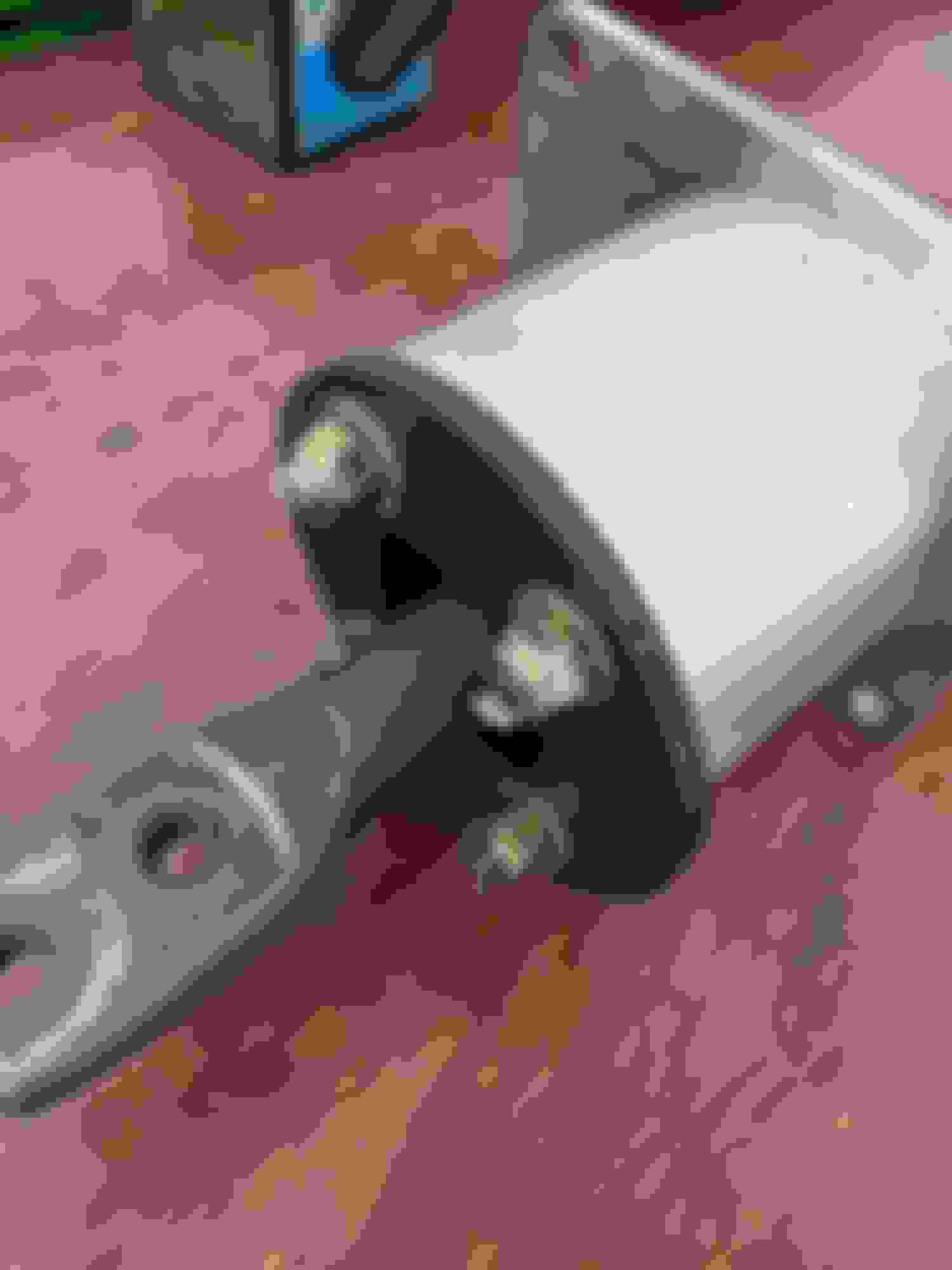
Mine were designed to be as simple as possible. One flange matches the trans. One matches transfer case. Tubing was cut for the excess length between the two. Adapter components
Next we used a lathe to accommodate the lips on the main components. A lip on the connecting tube was added to align and reinforce the adapter. Transfer case flange Tube slip fit Three pieces tack welded Test fit
Hard part really is over. The rest is just mixing off the shelf parts.
Mid shift conversion and shifter:
There are a few options for parts and guides out there. This is just like any t56 install in a truck where the normal fbody shifter location won't work. Oh and we are using a vette tail housing so there isn't a shifter location.
A few points worth highlighting though. Shifter choices and loss of reverse lockout. Shift rail also needs modified but covered below.
Core shifters has way more options to fit your needs. I used a hacked up Mustang shifter for years that did not have the correct pivot point for a 12" long shifter in a truck and leaked fluid because the bolt holes were butchered to get it to bolt down. That said Core Shifters use a 3/8 bolt with 3 threads in a 1/8 base plate to hold the things together. I'll do a separate review on YT or something eventually. Aside from this awful flaw they make a great product that just needs a little extra engineering. Threads stripped out in less than 100 miles Test fitting new grade 8 bolts - 1 already welded into plate Pass through studs now with adequate hardware
We lose reverse lockout because the mid shift conversion replaces the shift selector and the shifter is now bolted where the lockout housing is on a corvette. I've seen a few solutions for this but haven't been able to make any work. I have added additional material to the shift detent plate and selector to make it more difficult to get into the reverse gate - but it is still possible. Normal upshifts I have never hit reverse while driving. Downshifting from 6th to 5th I manage to grind reverse fairly often. For now my solution is to always go to 4th for a downshift. This extra glob causes extra load on the detent to get over to the reverse gate. Next time I will make it even larger. Similar thought - The extra material on the plate creates more resistance for the ball bearing - very limited clearance though
Building the transmission:
Assuming you know how to assemble a t56. This is only a highlight of the differences vs a normal build.
The main shift rail needs to be cut down on both ends. An fbody shift rail would save this step but we already have the corvette one available.
The shift selector end is easy. Slide the selector on and cut it past the roll pin. (See pic above with shift pate/selector)
The other end normally goes through the midplate and connects to the shifter on the torque tube. Assemble the trans with the vette mid plate, shift rail, 1/2 and 3/4 forks, and mainshaft. Engage forth gear. Mark the rail where it extends past the midplate. Mark the rail where it just enters the midplate. Disassemble again. Goal is to cut the shaft so it is still supported by the mid plate but does not extend past it. When swapping to the fbody mid plate we need enough room for 4th to engage without bottoming out. Bevel the shaft after cutting. Modified rail vs stock vette reail. The Steel 3/4 fork is on the modified rail. Shift selector end. Keep enough material to secure selector with roll pin. Mid plate end. The dowel is discarded but the hole is a good reference point.
Now we swap to the fbody mid plate. Assemble as normal. Shim your preload for main and counter shaft. Fbody midplate Front half a trans with modified rail and fbody mid plate
Back half of transmission assembles like normal. Remember to use your m12 rod to shim the countershaft extension.
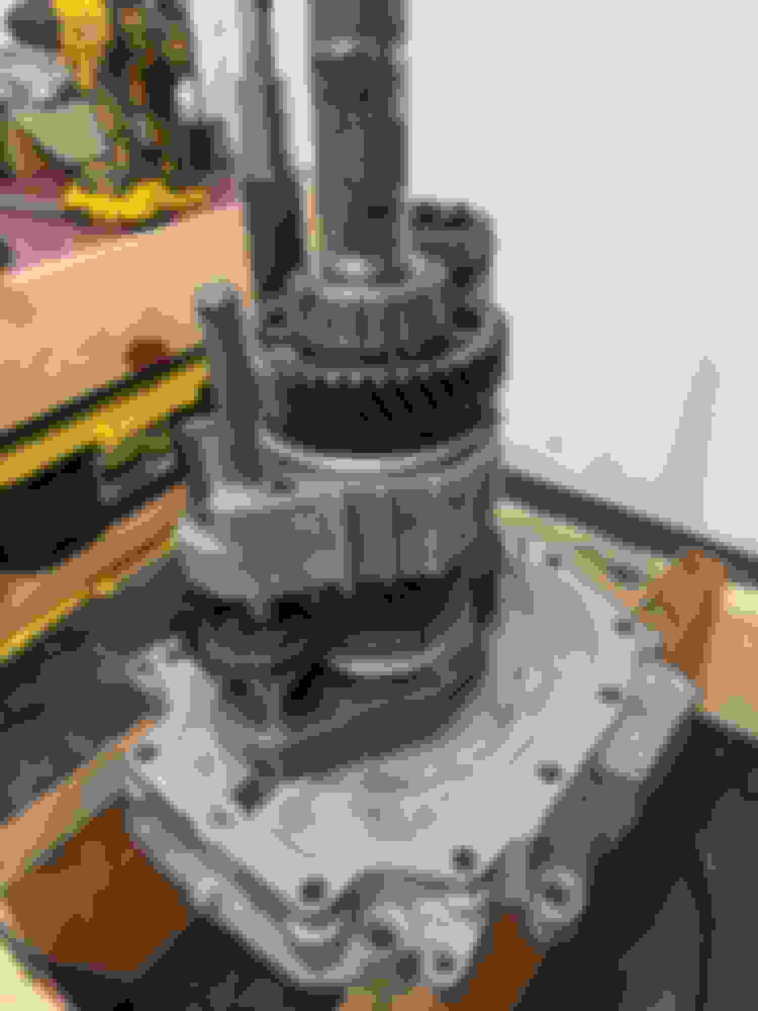
If you want to shorten the mainshaft now is the time to cut it. The splines on the output are longer than the splines in the BW4472. I cut
about 1.25 inches off of mine and accounted for this in my adapter plate. I do not know if it really makes things any stronger but this eliminates the hollow end section of the shaft and I would think the shorter the shaft the less likely it is to break. Bevel the edges.
Shortened shaft leftovers - section is hollow for some reason
Now add bellhousing and transfer case Completed behemoth
Alternative builds:
The process would be very similar for a 6060. It would result in a stronger trans overall and have better shifter options since they already support the mid shift location. Note the z06 6060 is 30 spline.
Tough part with other combinations is matching spline count. You can get an aftermarket 32 spline input shaft for the BW4472. This opens up some options such as the beefier t56 mainshaft.
4l80e is probably the best overall option. It is easier to build a strong trans and with the aftermarket input for the BW4472 you have a true bolt together option. Albeit not great for those of us who like to row gears.
Final thoughts:
Hope this helps. Let me know if something needs clarified.
Last edited by Gabbiani; Sep 27, 2020 at 12:25 PM.
Quick thoughts after my first read of it.
F and Vette input shafts being "the same" should be clarified as the functional length. Ratio and synchronization section(s) vary.
Shortening the mainshaft won't strengthen it in any way that applies to this build.
The use of a shorter mainshaft from another model would require creative addition of surface(s) for the Vette tailhousing seals.
Nice write-up.
Thanks - I've removed the comment about the input shaft. It didn't really add anything and I could see it causing confusion on other builds. Point here should be if you start with a vette trans you can use all the internals from it for this build.
I would love to see some pictures from underneath to show how the front shaft and diff are set up (I don't know much about truck 4wd setups). And how does is drive on the street? :-)
I would love to see some pictures from underneath to show how the front shaft and diff are set up (I don't know much about truck 4wd setups). And how does is drive on the street? :-)
CP said the truck they modelled their mounts on had a body lift....
I don't have many but will try to grab some next time it is in the air. It is tight. I hate the Milodon steel pan but not many options for ls and 4wd in an S10. The diff is mostly in the stock spot. Dropped the mounting tabs maybe an inch by cutting and rewelding them. Drive shaft was easy as taking the flanges to a local shop with measurements. Thankfully angles worked out relatively close. I have not done anything to tweak the pinion angles.
It drives fantastic. Over 800ftlbs of tq and it just goes. I can drop the clutch from a stop with the 2step on. That being said it still isn't easy to launch. Not auto easy anyways. Worlds better than living with a boosted rwd car. I've run cheap Sumitomos and currently have 275 17 ET Streets. When it was stock open front diff and street tires it would sometimes spin below 60. With the limited slip up front and ETs it is like glue.
ive been slowly collecting parts to do this for a future project, but with slight differences.
SSR main shaft is 32 spline and i was able to just buy one from rockauto for like $94. general consensus is that will allow the c5 t56 to hold 1000hp.
if you get one of these and a 4l80e conversion input shaft for your transfer case, you can increase the power handling since the 27 spline input seems to be the fuse in the system.
I have a np149 from a silverado ss with the bigger input shaft for my build.
can you measure the overall length of the package?
Great work. But I have a question about choosing a mid-plate and bellhousing... Is it true that the F-body pieces cause the transmission to be rotated about the axis centerline? In your photo above, everything appears to be straight up, but there are a lot of questions online about this rotation issue. I've even noticed on ads for bellhousings that say the F-body version is not compatible with other applications.
I also read somewhere that certain LS bellhousing applications require a special, more expensive starter. DO you have any information on that to share.
Awesome and thanks for sharing this.... maybe offer a kit for people wanting to duplicate it?
Crazy to see that plain Jane C5 transaxle taking all this abuse!
innerloop- A GTO bellhousing needs a GTO starter.... Fbody bellhousing (LS1 style) can't use pretty much any LS starter (not sure about the GTO starter). Most prefer the truck style starter which has 2 long bolts.... the Fbody style starters can sometimes crack the short ear off of the housing... which potentially if it rocked while starting on the block.... could crack the block and/or mess up your flywheel.
I hope I'm not too forward, but I signed up for this forum because of this build. I'm looking to do a very similar thing to a 1st gen blazer, and I'm a machinist. Are there any DXF, STEP or IGES files for that adapter? Maybe a print?
I would be very grateful.
Two and a half years later no reply... I am also trying to figure this out. Looks like 1" thick plates. I have a C5 tail and will trace this out and reply here. NP 149 pending removal
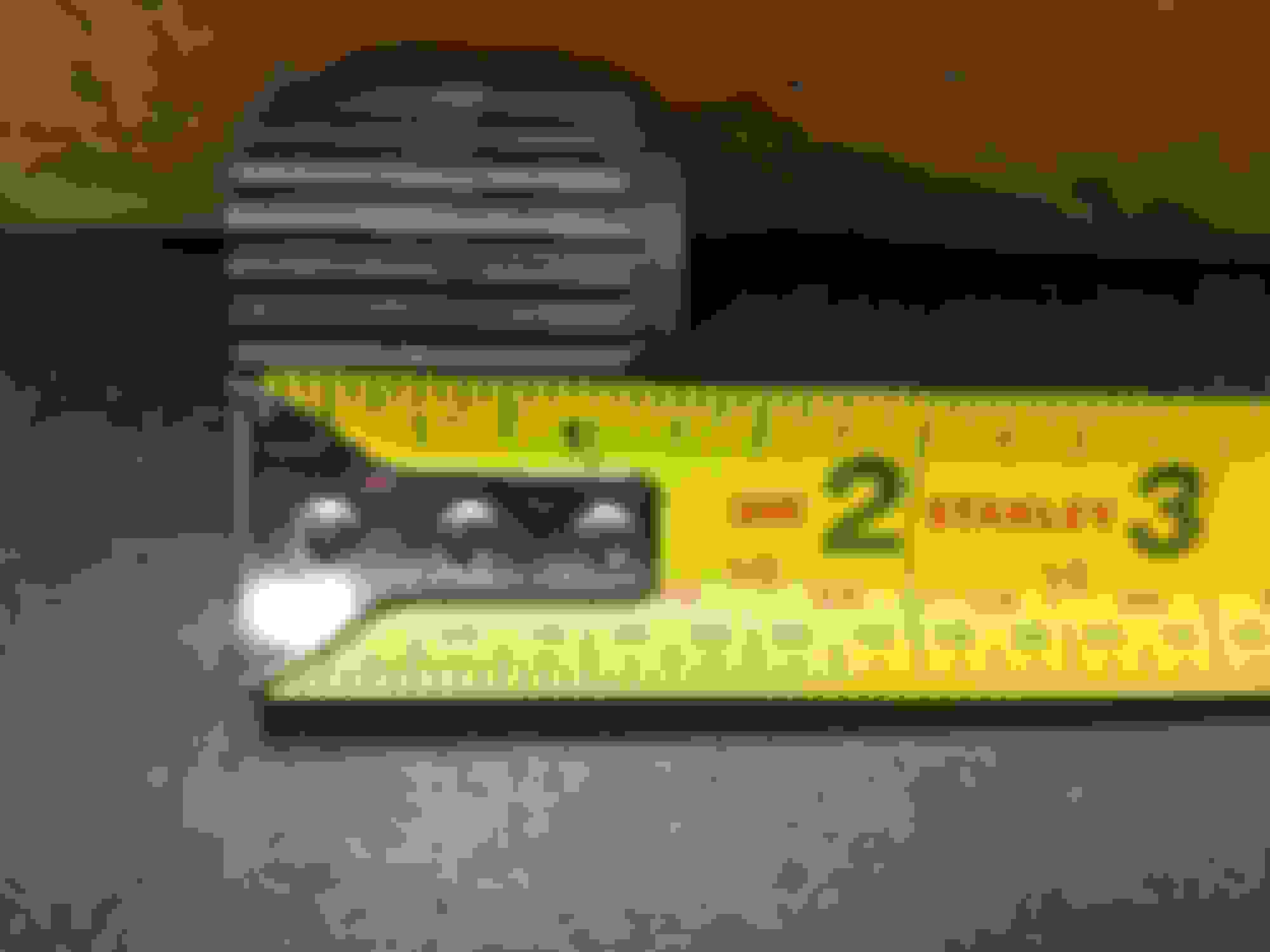
EDIT: I tried to use the smartdraw but my trial period is done so it didn't let me download it so I had to use word. I took some pictures and the micrometer is pretty accurate for being a cheap tool. this was just to get the diameters of the C5 tail. As mentioned by michael metal on youtube, there are different C5 tails so I think the one I got from tx drivetrain, may not fitup https://www.txdrivetrain.com/product...-tailhousings/
Anyway, here are the measurements if anyone wants to put this into a CAD and share.
Last edited by recoveringmekanic808; Oct 24, 2025 at 10:45 AM.
Reason: Adding picture
I've had this thread open as reference for a while now. I just called Tick Performance as I'm much closer to getting this done and may not have time to experiment in my first manual transmission rebuild. Tick Performance said I could not use an SSR mainshaft with the C6 T56 tail housing due to the size. Has anyone tried this? I have the SSR 32 spline main shaft and an adaptor for my BW4472. I was hoping to build something quite strong rather than the 27 spline version.
I've had this thread open as reference for a while now. I just called Tick Performance as I'm much closer to getting this done and may not have time to experiment in my first manual transmission rebuild. Tick Performance said I could not use an SSR mainshaft with the C6 T56 tail housing due to the size. Has anyone tried this? I have the SSR 32 spline main shaft and an adaptor for my BW4472. I was hoping to build something quite strong rather than the 27 spline version.
have you found anything else out about this yet? I have an obs four door Tahoe I have ls swapped and am building a 408 for and I�d love to be able to run a t56 or tr6060 with my awd setup I have now behind my 4l60e. Feel like with the little room I have behind the transfer case now I�d need to abandon the tail housing all together and build a full custom tail housing to get much needed space back since it�s all but touching the cross member at the front of my fuel tank already