


Corvette Custom Nitrous Kit Install Tutorial
First and foremost, I want to give a HUGE thank you to the guys at Nitrous Outlet. I would not have been able to get this done efficiently without the help of Neal, Chris, and Dave. They were extremely supportive. Even to a guy that only purchased an FPSS and fuse block new. Without a shadow of a doubt they will be who I turn to for all my nitrous needs. I also want to thank Beer99C5 for answering some of my basic newb questions I had, and for his great threads filled with TONS of information, before I even started.
I wanted to document the installation and fabrication of my nitrous install. I thought this may help others that like to see pictures to follow along, since a lot of times that is missing. I know Beer and others have made some great threads in the past, which i used in my research, but I wanted to also show how I did mine to give others a view. I wasnt necessarily going for a stealth look, just a "clean" look. So, with that said, here is my procedure:
Link to purge line installation:
https://ls1tech.com/forums/nitrous-o...intensive.html
First I removed the interior stuff that i wanted out of my way, this included:
-Center console, including armrest and headunit pieces
-knee panel
(for those that need instructions, a good how-to is here: http://www.vetteessentials.com/instr...zel_howto.html)
-passenger footwell kick panel, and "knee panel" that hides wiring and firewall harness hole
-rocker panel covers - covers behind seat.
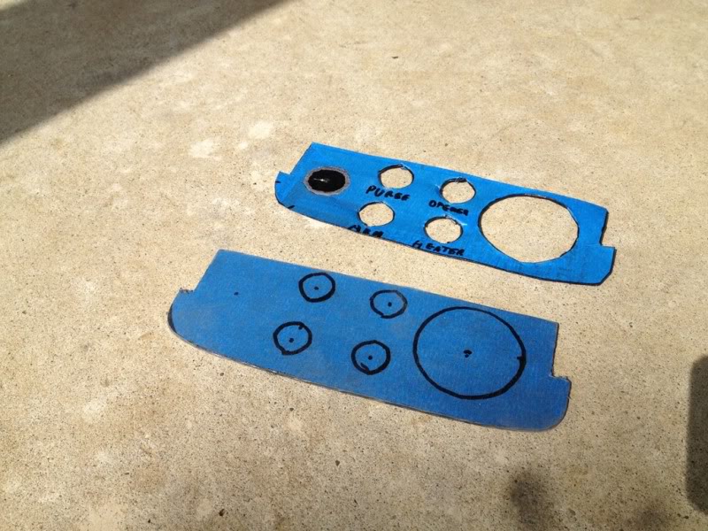
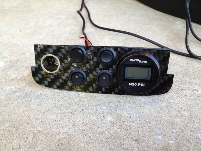
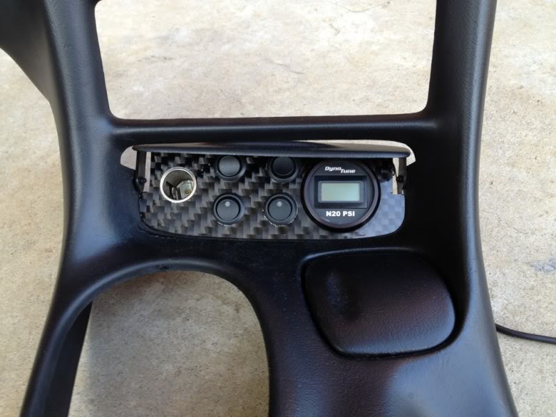
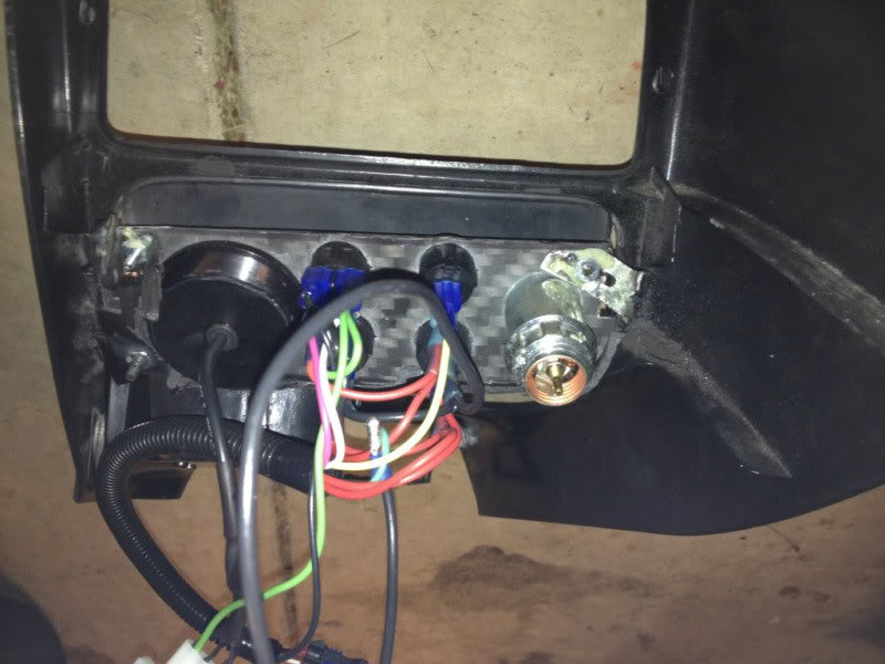
I decided I didnt like the 'premade' switch panels that much, and wanted to do my own. So, with the instrument panel trim, I then traced a cardboard cutout of the ashtray opening, and tired 3-4 different designs and decided I liked the full cover the best, and decided to integrate the 12V receptacle into it. I purchased round rocker switches for all the switches including purge, since i thought it looked the most 'clean'.
And with the test fit...
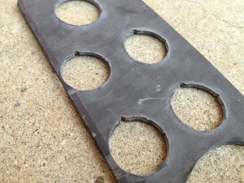
Next I covered my piece of carbon fiber board (I bought a 6"x8" 2mm thick sheet on ebay for $10... I will not do this again, as it is a HUGE twill, and had several porosity spots in it, but will do for now) using some masking tape, then traced my cardboard cutout, and used a dremel with a cutting wheel (for plastic) to cut the outline out
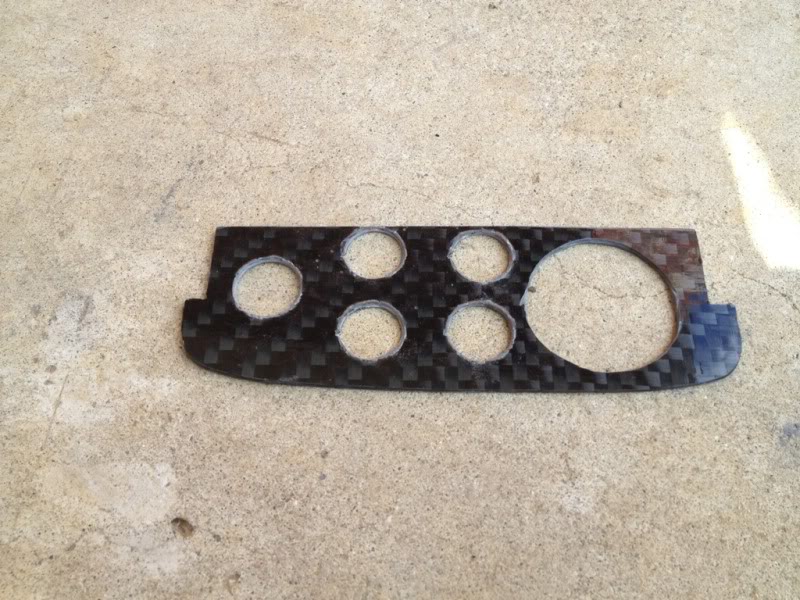
Next i used a combination of a drill, cutting wheel, and sanding wheel, to get the holes cut. I then used a file to cut in the clocking feature for the buttons.
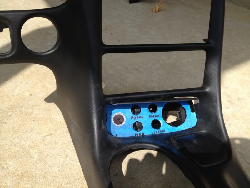
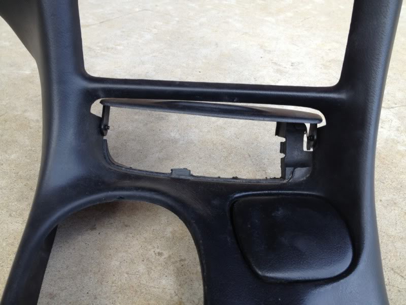
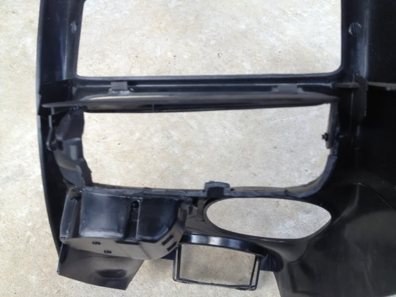
Next, I cut out the ashtray area from the trim piece. With hindsight being 20/20, I would have taken more care to not cutout the top half, to give the panel more area to rest on/support points. I will show my resolution to this mistake later.
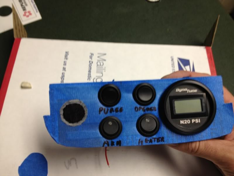
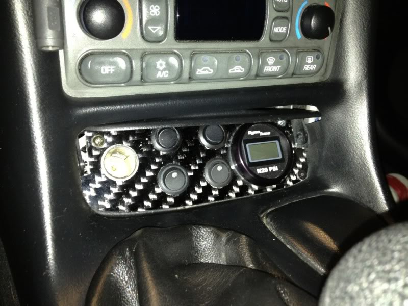
I then installed the buttons, n2o pressure gauge, and 12V plug into the panel, and test fit again.
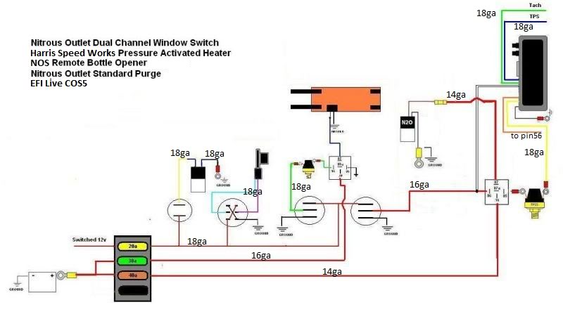
The next step was to start wiring. Here is the diagram I modified from an existing one on LS1Tech. (No fuel solenoid as it is a dry shot, easy to add by pigtailling on n2o solenoid)
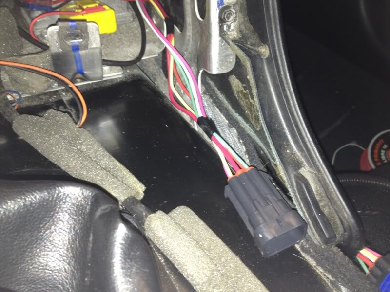
I first completed the wiring on the switch panel. I decided on 3 connectors in the end, I kept the ground wire independant because I wanst sure at the time where I wanted to route it, the other contains all the switch panel leads, and the 3rd is for the n2o pressure gauge. I kept it separate in case I ever decide to replace it, or move it to another location. I tapped the power and ground for the gauge into the power and ground on the switches as shown below.
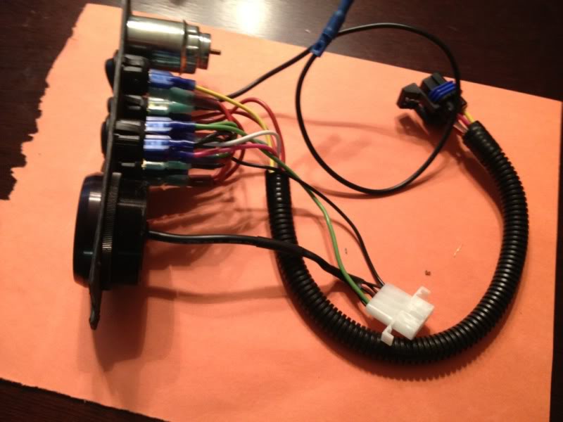
I then ran the free end of my spools of wire from the passenger footwell up to the dash area, pinned the wires for the plug, then completed the plug install. For the ground it was ran from the drivers side as I decided to ground the switch panel to the ground location behind the driver's side seat below the seatbelt mount.
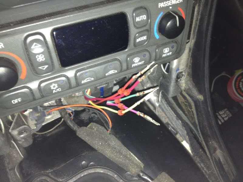
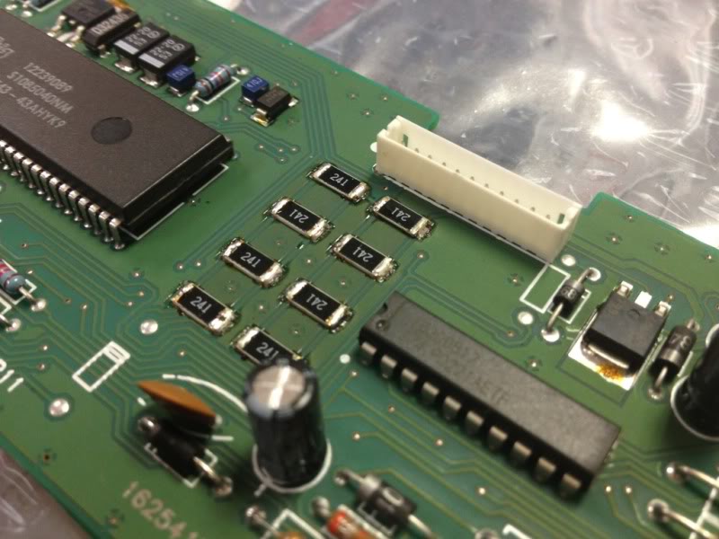
On a side note, while I had everything apart, I also removed the climate control unit to fix the display dimming problem. (how-to found: http://forums.corvetteforum.com/c5-t...splay-fix.html)
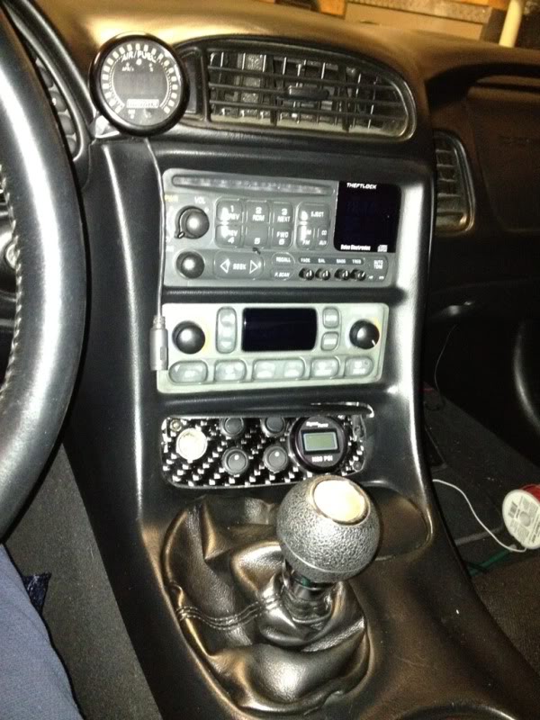
Here is the switch installed on the instrument panel trim: I used a piece of metal to create a bracket and used plastic epoxy to secure it to the trim. I then drilled 3 holes in the panel and trim for bolts. I epoxied the nuts to the backside so that I could remove the switch panel by itself w/o needing to take the dash out, if I wished.
I then reinstalled to test fit.
(flash made the climate control look funny, it really doesnt look washed out like that )
)
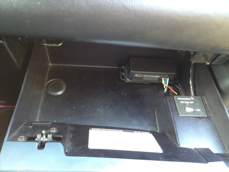
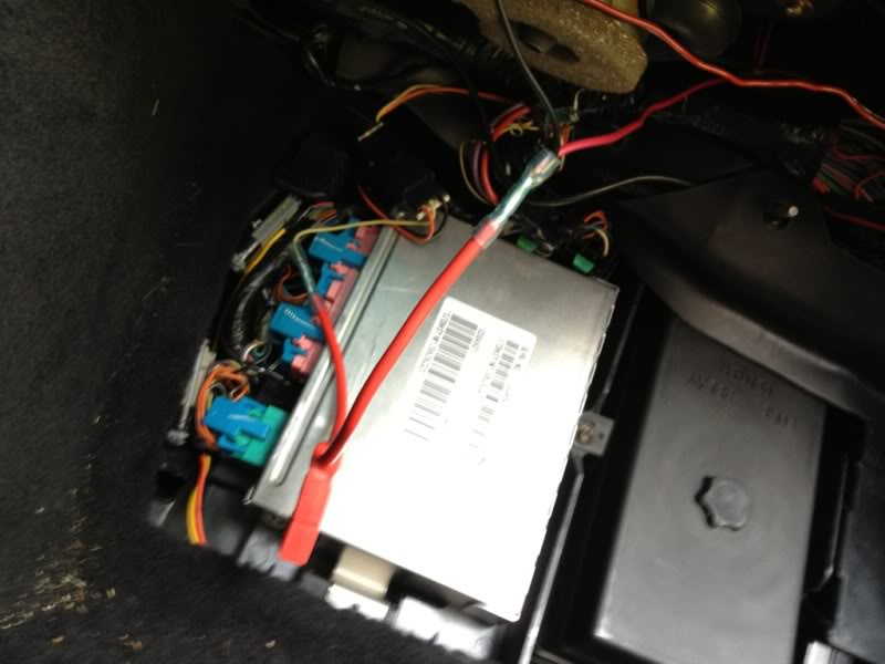
Next is the Nitrous Outlet 2-stage window switch w/ integrated WOT switch (older unit, same as Trick Performance unit). After examining several locations, such as in the center console, under the drivers knee panel, in the battery compartment in the engine bay, etc... I settled on having it in the glovebox.
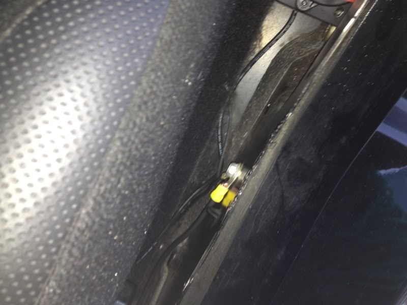
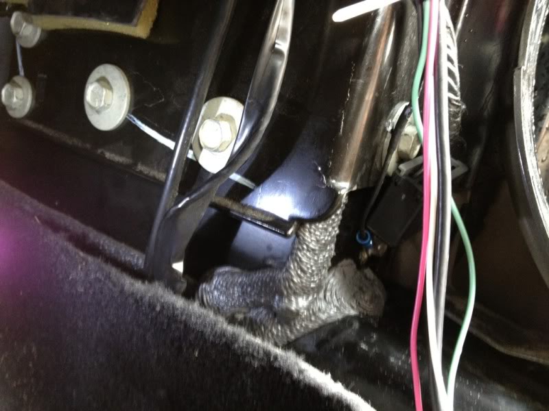
After one of my conversations with the guys at Nitrous Outlet, I grounded the unit on it's own grounding source from the rest of the system. Which I chose on the ground point of the passenger side foot panel/near door hinge. I then routed the remote opener wires + heater arm wire back along this rocker area to the trunk. I ran the heater battery 12V connection from the trunk up through this area as well
I ran the ground for the heater from the relay and from the heater itself through a couple holes that were in the bottom of the well, up to the ground on the back of the frame rail, which I got access to by removing the taillights.
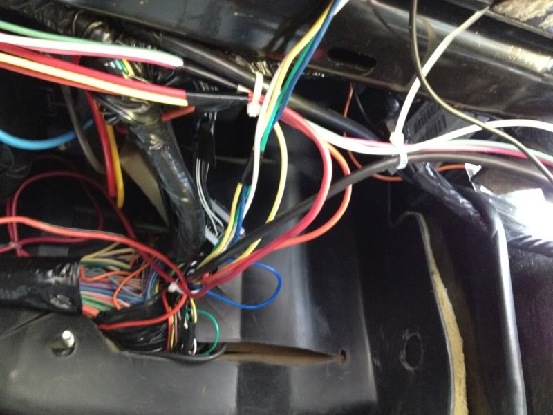
I then ran the following wires through the firewall:
-Heater battery 12V
-Purge comm from switch
-tach wire from window switch
-TPS wire from window switch
-arm comm from switch (with white wire from window switch tapped in)
(already going through is the innovate widedband 'stuff')
Then pulled things snug and tied off so they wouldnt slack.
I wired the switched 12V from the switch panel (and my traction control box which sets car back to previous setting when keyed on, so I dont have to remember to put it in comp driving or TC-off every time I start the car which comes in really handy at the track or drag strip) into the yellow switched 12V source that was left open from the factory with an inline fuse holder. I used this source because the innovate WB, XD-16, are tapped into the open fuse spot at the passenger footwell
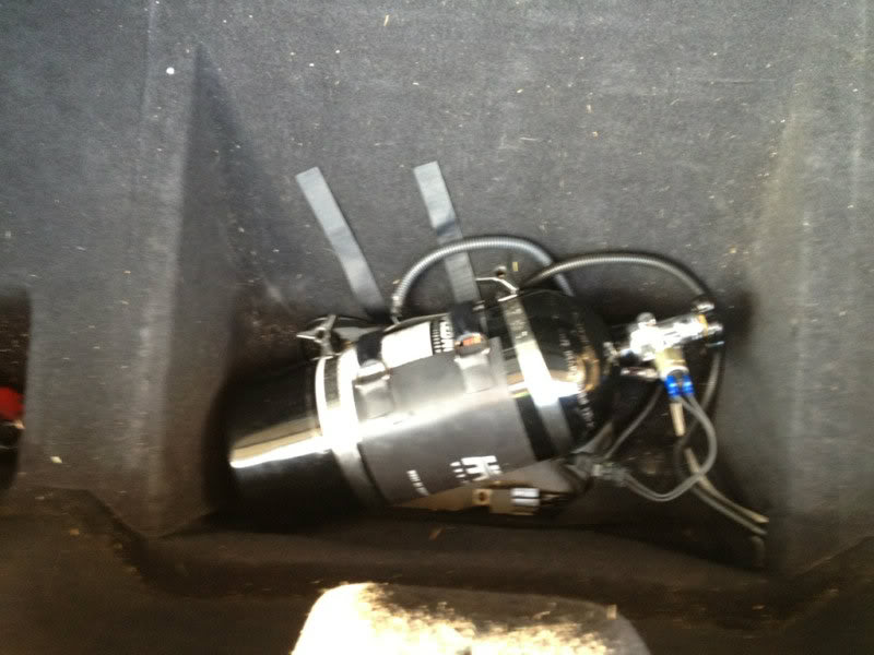
Back in the trunk area, I wired the relay, routed the n2o pressure gauge (which was routed along the drivers side rocker through the back), and put it all together. The wooden board that holds the n2o bottle was cut to fit, painted black, and epoxied to the foot well flat spots. (please ignore dirt in the picture, havent had a chance to vacuum yet)
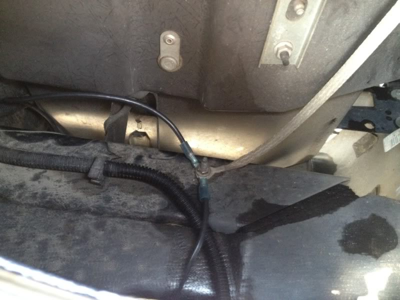
For the nitrous feed, I decided to route the line out of the cabin through the hole for the antenna (my radio antenna is now a high-power unit that is located behind the rearview mirror, so didnt need it), and then up over the passenger wheel well, and through the rocker panel hole, then up under the battery tray and emerges out by the surge tank.

I wanted to document the installation and fabrication of my nitrous install. I thought this may help others that like to see pictures to follow along, since a lot of times that is missing. I know Beer and others have made some great threads in the past, which i used in my research, but I wanted to also show how I did mine to give others a view. I wasnt necessarily going for a stealth look, just a "clean" look. So, with that said, here is my procedure:
Link to purge line installation:
https://ls1tech.com/forums/nitrous-o...intensive.html
First I removed the interior stuff that i wanted out of my way, this included:
-Center console, including armrest and headunit pieces
-knee panel
(for those that need instructions, a good how-to is here: http://www.vetteessentials.com/instr...zel_howto.html)
-passenger footwell kick panel, and "knee panel" that hides wiring and firewall harness hole
-rocker panel covers - covers behind seat.
I decided I didnt like the 'premade' switch panels that much, and wanted to do my own. So, with the instrument panel trim, I then traced a cardboard cutout of the ashtray opening, and tired 3-4 different designs and decided I liked the full cover the best, and decided to integrate the 12V receptacle into it. I purchased round rocker switches for all the switches including purge, since i thought it looked the most 'clean'.
And with the test fit...
Next I covered my piece of carbon fiber board (I bought a 6"x8" 2mm thick sheet on ebay for $10... I will not do this again, as it is a HUGE twill, and had several porosity spots in it, but will do for now) using some masking tape, then traced my cardboard cutout, and used a dremel with a cutting wheel (for plastic) to cut the outline out
Next i used a combination of a drill, cutting wheel, and sanding wheel, to get the holes cut. I then used a file to cut in the clocking feature for the buttons.
Next, I cut out the ashtray area from the trim piece. With hindsight being 20/20, I would have taken more care to not cutout the top half, to give the panel more area to rest on/support points. I will show my resolution to this mistake later.
I then installed the buttons, n2o pressure gauge, and 12V plug into the panel, and test fit again.
The next step was to start wiring. Here is the diagram I modified from an existing one on LS1Tech. (No fuel solenoid as it is a dry shot, easy to add by pigtailling on n2o solenoid)
I first completed the wiring on the switch panel. I decided on 3 connectors in the end, I kept the ground wire independant because I wanst sure at the time where I wanted to route it, the other contains all the switch panel leads, and the 3rd is for the n2o pressure gauge. I kept it separate in case I ever decide to replace it, or move it to another location. I tapped the power and ground for the gauge into the power and ground on the switches as shown below.
I then ran the free end of my spools of wire from the passenger footwell up to the dash area, pinned the wires for the plug, then completed the plug install. For the ground it was ran from the drivers side as I decided to ground the switch panel to the ground location behind the driver's side seat below the seatbelt mount.
On a side note, while I had everything apart, I also removed the climate control unit to fix the display dimming problem. (how-to found: http://forums.corvetteforum.com/c5-t...splay-fix.html)
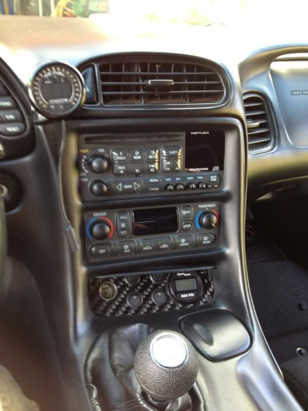
Here is the switch installed on the instrument panel trim: I used a piece of metal to create a bracket and used plastic epoxy to secure it to the trim. I then drilled 3 holes in the panel and trim for bolts. I epoxied the nuts to the backside so that I could remove the switch panel by itself w/o needing to take the dash out, if I wished.
I then reinstalled to test fit.
(flash made the climate control look funny, it really doesnt look washed out like that
Next is the Nitrous Outlet 2-stage window switch w/ integrated WOT switch (older unit, same as Trick Performance unit). After examining several locations, such as in the center console, under the drivers knee panel, in the battery compartment in the engine bay, etc... I settled on having it in the glovebox.
After one of my conversations with the guys at Nitrous Outlet, I grounded the unit on it's own grounding source from the rest of the system. Which I chose on the ground point of the passenger side foot panel/near door hinge. I then routed the remote opener wires + heater arm wire back along this rocker area to the trunk. I ran the heater battery 12V connection from the trunk up through this area as well
I ran the ground for the heater from the relay and from the heater itself through a couple holes that were in the bottom of the well, up to the ground on the back of the frame rail, which I got access to by removing the taillights.
I then ran the following wires through the firewall:
-Heater battery 12V
-Purge comm from switch
-tach wire from window switch
-TPS wire from window switch
-arm comm from switch (with white wire from window switch tapped in)
(already going through is the innovate widedband 'stuff')
Then pulled things snug and tied off so they wouldnt slack.
I wired the switched 12V from the switch panel (and my traction control box which sets car back to previous setting when keyed on, so I dont have to remember to put it in comp driving or TC-off every time I start the car which comes in really handy at the track or drag strip) into the yellow switched 12V source that was left open from the factory with an inline fuse holder. I used this source because the innovate WB, XD-16, are tapped into the open fuse spot at the passenger footwell
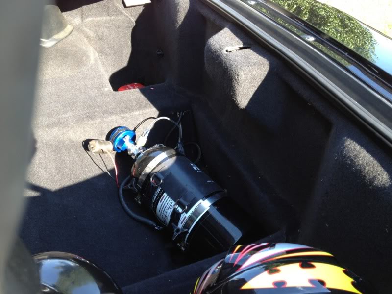
Back in the trunk area, I wired the relay, routed the n2o pressure gauge (which was routed along the drivers side rocker through the back), and put it all together. The wooden board that holds the n2o bottle was cut to fit, painted black, and epoxied to the foot well flat spots. (please ignore dirt in the picture, havent had a chance to vacuum yet)
For the nitrous feed, I decided to route the line out of the cabin through the hole for the antenna (my radio antenna is now a high-power unit that is located behind the rearview mirror, so didnt need it), and then up over the passenger wheel well, and through the rocker panel hole, then up under the battery tray and emerges out by the surge tank.
Last edited by Juicedh22; Jul 23, 2012 at 11:04 AM.
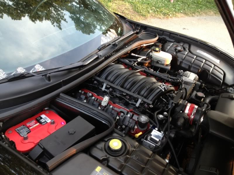
With the trunk area completed, it was time to move to the engine bay.
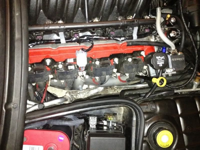
For the solenoid mount, for now i am using one of the brackets that came with the kit, until I can make something nicer and more stiff. It took me awhile to settle on where to mount the solenoids, but in the end I decided to mount it off the passenger head, with the added difficulty of having to work around the PCV catch can stuff. I installed the n2o plate kit from HSW (which in the future will be swapped out for a Nitrous Outlet unit, or an LMR 102mm TB w/ integrated nitrous port, if I can find one!!) Since i have an ls2 throttlebody with the motor on the passenger side, I did NOT need to relocate the power steering resevoir.
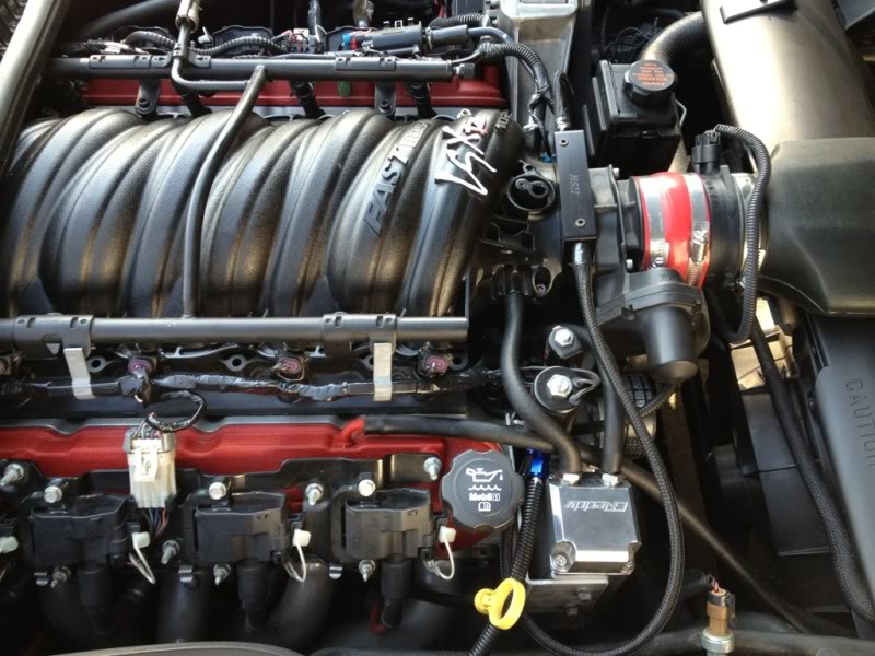
I covered the n2o feed lines that came with the kit with wire loom to keep a clean look. The drivers side feed line routes under the manifold/TB and into the T fitting on the solenoid, you can see the passenger side routing in the picture. The main feed makes a short jump from the surge tank to the solenoid, also covered in wire loom. I still have to route the purge line.
(I will add some close up shots of the solenoid mount later)
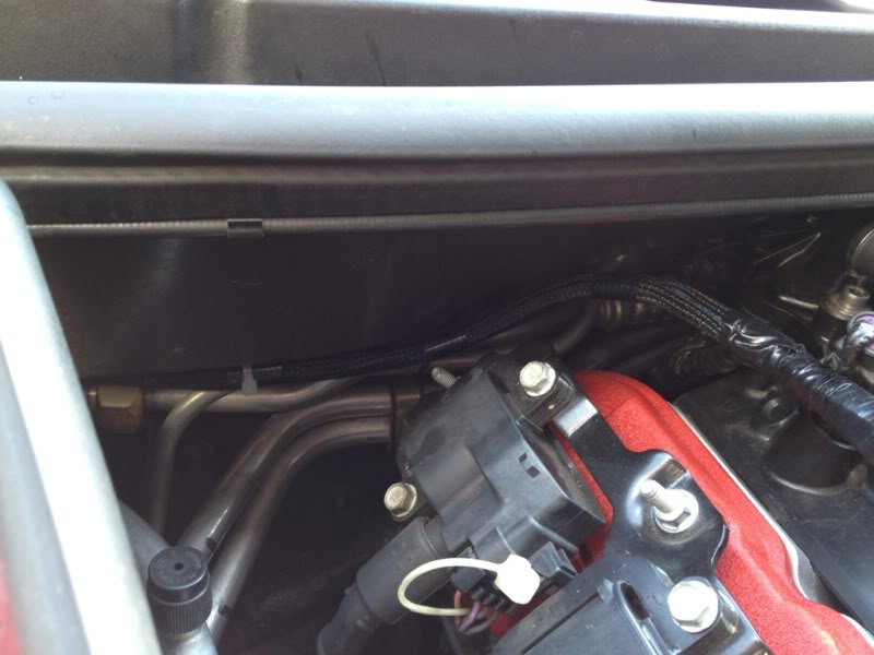
Next, with the battery and plastic shield removed, I routed the purge activation, tach, TPS, n2o 12V, and solenoid grounds from the battery area up along the main harness on the passenger head. I followed Beer's pictures and tapped into the pale green wire on the coil pack connector, and the blue wire for the TPS (I had to remove all the factory electrical tape, as the blue wire had faded green so I needed to confirm which one it was). I tied the ground for both solenoids together and used a 10ga wire to lead the ground back to the main chassis ground in front of the battery. The n2o 12V is a 12ga wire, just to make sure it has plenty of juice.
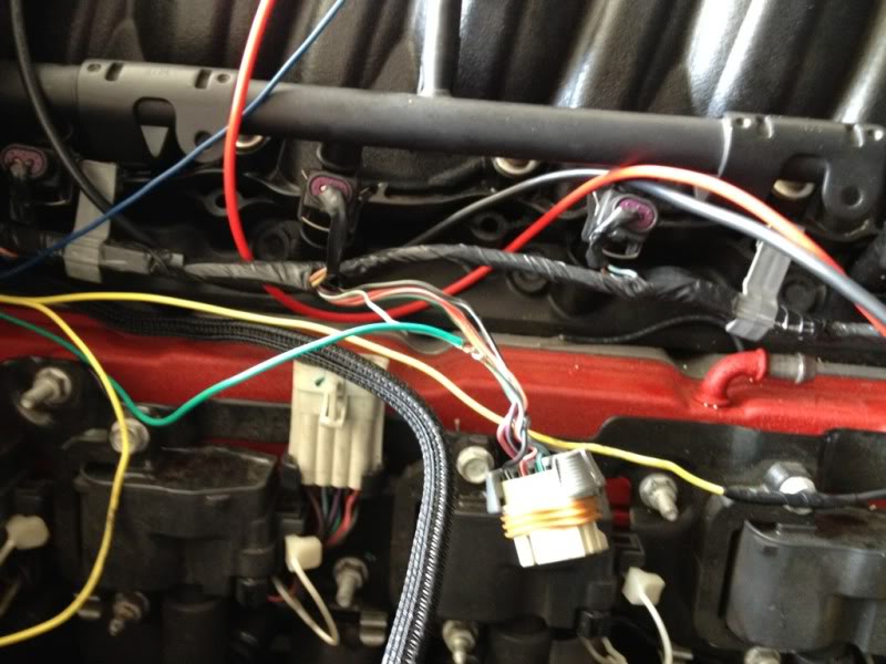
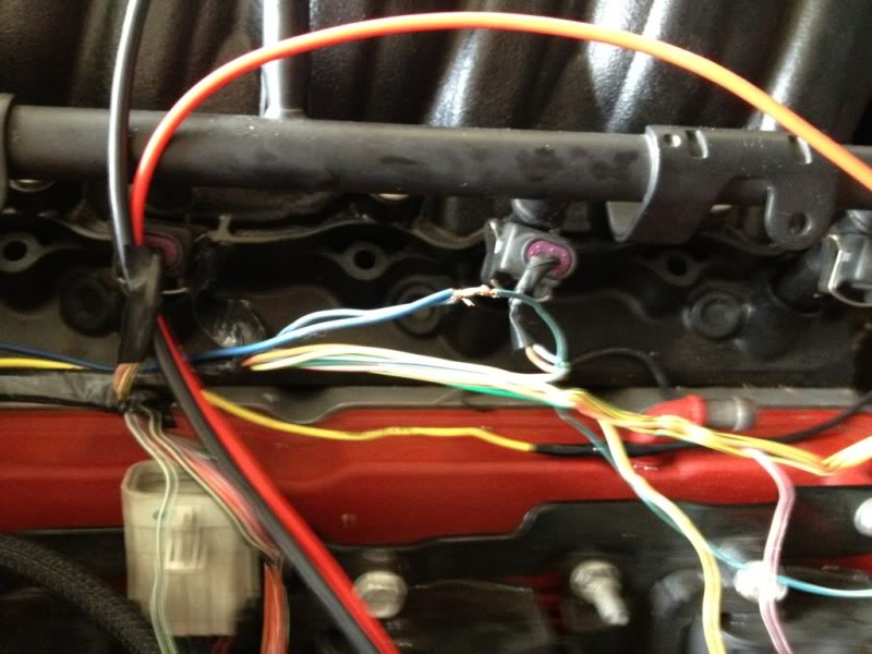
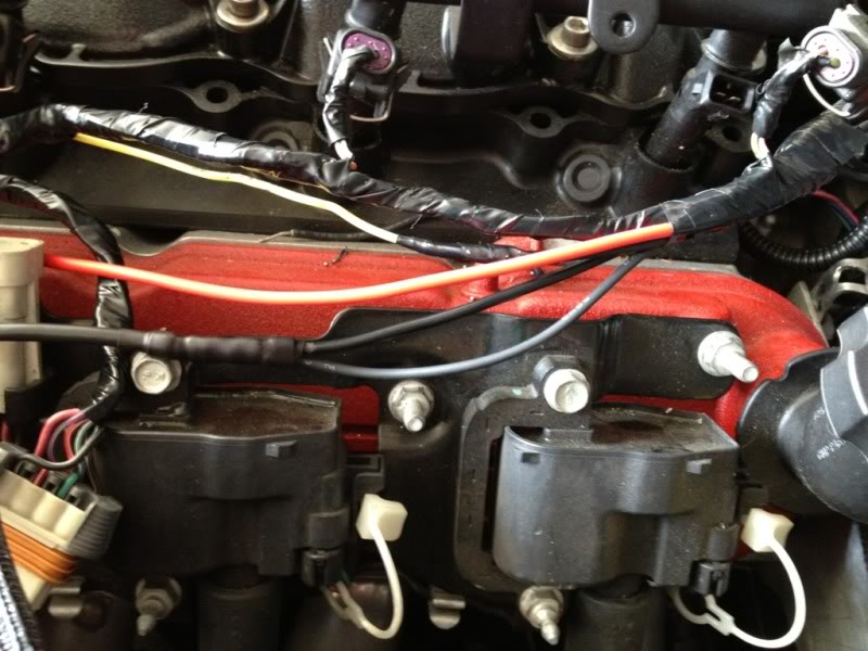
I then re-wrapped the harness with fresh electrical tape, and put loom over the wires at the firewall. and connected everything. (photo is actually from the job complete, but is poor resolution, need to get a better shot)

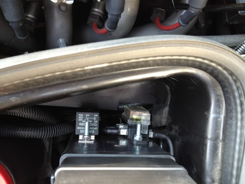
Back in the battery box area, I decided to mount my fuse block and n2o relay to the side of the large fuse panel. I unbolted it, and removed the lower cover, drilled mounting holes and use bolts w/ locking nuts to secure them. I then reinstalled. I ran the heater 12V and n2o 12V on their own 10ga wire from the (+)terminal post that is on the fuse panel side to the fuse block. I pulled out all the wires that were already on the relay connector and made my own directly from the wires I had ran, to minimize solder joints.

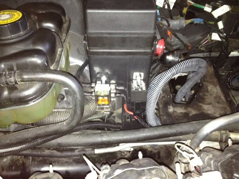
(ignore the large grey looking loom, that is for the wideband, I kept the wires from the 'as purchased' length since I only plan on having the wideband in there for tuning purposes, then will remove.)
(I will take some better resolution shots of detailed finish work later, I ran out of time last night, and want to clean everything up first)
For the solenoid mount, for now i am using one of the brackets that came with the kit, until I can make something nicer and more stiff. It took me awhile to settle on where to mount the solenoids, but in the end I decided to mount it off the passenger head, with the added difficulty of having to work around the PCV catch can stuff. I installed the n2o plate kit from HSW (which in the future will be swapped out for a Nitrous Outlet unit, or an LMR 102mm TB w/ integrated nitrous port, if I can find one!!) Since i have an ls2 throttlebody with the motor on the passenger side, I did NOT need to relocate the power steering resevoir.
I covered the n2o feed lines that came with the kit with wire loom to keep a clean look. The drivers side feed line routes under the manifold/TB and into the T fitting on the solenoid, you can see the passenger side routing in the picture. The main feed makes a short jump from the surge tank to the solenoid, also covered in wire loom. I still have to route the purge line.
(I will add some close up shots of the solenoid mount later)
Next, with the battery and plastic shield removed, I routed the purge activation, tach, TPS, n2o 12V, and solenoid grounds from the battery area up along the main harness on the passenger head. I followed Beer's pictures and tapped into the pale green wire on the coil pack connector, and the blue wire for the TPS (I had to remove all the factory electrical tape, as the blue wire had faded green so I needed to confirm which one it was). I tied the ground for both solenoids together and used a 10ga wire to lead the ground back to the main chassis ground in front of the battery. The n2o 12V is a 12ga wire, just to make sure it has plenty of juice.
I then re-wrapped the harness with fresh electrical tape, and put loom over the wires at the firewall. and connected everything. (photo is actually from the job complete, but is poor resolution, need to get a better shot)
Back in the battery box area, I decided to mount my fuse block and n2o relay to the side of the large fuse panel. I unbolted it, and removed the lower cover, drilled mounting holes and use bolts w/ locking nuts to secure them. I then reinstalled. I ran the heater 12V and n2o 12V on their own 10ga wire from the (+)terminal post that is on the fuse panel side to the fuse block. I pulled out all the wires that were already on the relay connector and made my own directly from the wires I had ran, to minimize solder joints.
(ignore the large grey looking loom, that is for the wideband, I kept the wires from the 'as purchased' length since I only plan on having the wideband in there for tuning purposes, then will remove.)
(I will take some better resolution shots of detailed finish work later, I ran out of time last night, and want to clean everything up first)
Again, I can't say enough how thoroughly impressed I am with your customer support. Amazing to get that kind of support this day from any type of automotive aftermarket company.
Trending Topics
A few more pictures added....

Just waiting on some vinyl decals. I got the ones i ordered in the mail... turns out that 0.25" is bigger than I thought it would be, so need to find somewhere who can do smaller.
Just waiting on some vinyl decals. I got the ones i ordered in the mail... turns out that 0.25" is bigger than I thought it would be, so need to find somewhere who can do smaller.
LS1 Tech Stories
The Best V8 Stories One Small Block at Time

Topdon ONE vs. Artidiag 800 BT2: Which is the Diagnostic Tablet For You?
Pouria Savadkouei
Gas Monkey Built a 6-Wheel Ferrari Testarossa With a Corvette LT4 Engine
Verdad Gallardo
7 Most Reliable High-Performance Engines GM Has Ever Built
Verdad Gallardo
Amazing '71 Camaro Restomod Is Modern Muscle Car Under the Skin
Verdad Gallardo
6 Common C5 Corvette Failures and What's Involved In Repairing Them
Pouria Savadkouei
Retro Modern Bandit Pontiac Trans AM Comes With Burt Reynolds' Autograph
Verdad Gallardo
Top 10 Greatest Cadillac V Series Performance Models Ever, Ranked
Pouria Savadkouei
Top 10 Most Powerful Chevy Trucks Ever Made!

Hennessey's New Supercharged Silverado ZR2 Has 700 HP
Verdad Gallardo

bumping up this old thread but ? to the op... I see you have a power duct, do you also have the vararam installed? and any tips on getting the plate to fit with that setup? with my plate it seems that the power duct raises the red inlet about 3/4 of a inch too far up to making a good connection to my tb. Thanks and very nice install.
Last edited by igtabg1; Jul 12, 2012 at 10:22 PM.

That's a good looking install. I'm putting the finishing touches on my NX plate kit(wet) and should have it all done in the next day or 2.
+1,000,000 for it not being a HARD job but it is very time consuming, especially when you have a universal kit and have to essentially design everything aside from where to mount the plate. It looks great, nicely done
+1,000,000 for it not being a HARD job but it is very time consuming, especially when you have a universal kit and have to essentially design everything aside from where to mount the plate. It looks great, nicely done
bumping up this old thread but ? to the op... I see you have a power duct, do you also have the vararam installed? and any tips on getting the plate to fit with that setup? with my plate it seems that the power duct raises the red inlet about 3/4 of a inch too far up to making a good connection to my tb. Thanks and very nice install.
Now, it is even more simple. Since I am running COS5, and have been in speed density for 2 years anyway, I deleted my MAF all together to remove the 'choke' point/restriction. I ran my own custom IAT sensor setup to the front of the vararam to complete.

Thanks! Im actually doing a few more updates. Integrating my Lingenfelter LNC-003 launch control (soon as I figure out how to wire it like I want it), and going Wet as well. Probably a new dash for launch control switch, line lock, and cutouts. And going to make a cover to go over the bottle in the trunk.
I got a used lnc-001r from a member on here I'm goin to be using. Also, considering buying a used msd 8969 from a buddies friend for $60, will the msd window switch activate the noids once it reaches the set window or will it need an input from either a tps switch or a button in the car ill have to hold when I want to spray?

TECH Fanatic

Joined: Sep 2003
Posts: 1,058
Likes: 1
I see you have Pin56 triggered from N20 Controller. I have a suggestion.
Do not cycle COS5 ON/OFF using the progressive. This will cause spark spikes
during progressive use. The way I got around this was run channel 1 nitrous and channel 2 for COS5, but channel 2 has no progressive.
BTW, looks great. Almost good as mine. LOL.
Do not cycle COS5 ON/OFF using the progressive. This will cause spark spikes
during progressive use. The way I got around this was run channel 1 nitrous and channel 2 for COS5, but channel 2 has no progressive.
BTW, looks great. Almost good as mine. LOL.
Thanks for the heads up on the COS5!
PS, I am yet to see pictures of your setup all complete! I backed off on mine and just went with the 102mm plate... it should be more than enough for me for now... I will upgrade to DP when I am ready for that step, and since i have all the stuff now, it should be a more simple conversion in the future.
PS, I am yet to see pictures of your setup all complete! I backed off on mine and just went with the 102mm plate... it should be more than enough for me for now... I will upgrade to DP when I am ready for that step, and since i have all the stuff now, it should be a more simple conversion in the future.